JP4471908B2 - Vibration isolator and manufacturing method thereof - Google Patents
Vibration isolator and manufacturing method thereof Download PDFInfo
- Publication number
- JP4471908B2 JP4471908B2 JP2005265681A JP2005265681A JP4471908B2 JP 4471908 B2 JP4471908 B2 JP 4471908B2 JP 2005265681 A JP2005265681 A JP 2005265681A JP 2005265681 A JP2005265681 A JP 2005265681A JP 4471908 B2 JP4471908 B2 JP 4471908B2
- Authority
- JP
- Japan
- Prior art keywords
- cylinder
- rubber
- rubber elastic
- elastic body
- vibration isolator
- Prior art date
- Legal status (The legal status is an assumption and is not a legal conclusion. Google has not performed a legal analysis and makes no representation as to the accuracy of the status listed.)
- Expired - Lifetime
Links
Images


Landscapes
- Vibration Prevention Devices (AREA)
- Springs (AREA)
Description
本発明は、防振装置及びその製造方法に関するものである。 The present invention relates to a vibration isolator and a manufacturing method thereof.
従来より、例えば自動車のサスペンション用ブッシュとして用いられる防振装置が知られている(例えば特許文献1及び2を参照)。 Conventionally, for example, a vibration isolator used as a suspension bush for an automobile is known (see, for example, Patent Documents 1 and 2).
特許文献1及び2の防振装置は、金属製の内筒体と、その内筒体の外周囲に内筒体と同軸に設けられた樹脂製の外筒体と、それら両筒体の間に設けられ、両筒体を互いに連結するゴム弾性体とを備えたものである。 The vibration isolator of Patent Documents 1 and 2 includes a metal inner cylindrical body, a resin outer cylindrical body provided coaxially with the inner cylindrical body on the outer periphery of the inner cylindrical body, and a space between the two cylindrical bodies. And a rubber elastic body for connecting both cylinders to each other.
以下、これら防振装置の製造方法を示す。まず、内筒体をゴム射出成形用金型のキャビティにセットして、その状態でキャビティにゴムを射出・充填して、ゴム射出成形用金型を加熱する。ゴムの加硫後、ゴム射出成形用金型を離型する。これにより、ゴム弾性体が射出成形されて、内筒体とゴム弾性体とからなる成形品が作製される。次に、成形品を樹脂射出成形用金型のキャビティにセットして、その状態でキャビティに樹脂を射出・充填して、樹脂射出成形用金型を冷却する。樹脂の固化後、樹脂射出成形用金型を離型する。これにより、外筒体が射出成形されて、防振装置が作製される。 Hereinafter, the manufacturing method of these vibration isolator is shown. First, the inner cylinder is set in a cavity of a rubber injection mold, and in that state, rubber is injected and filled, and the rubber injection mold is heated. After rubber vulcanization, the rubber injection mold is released. Thereby, the rubber elastic body is injection-molded, and a molded product including the inner cylinder body and the rubber elastic body is manufactured. Next, the molded product is set in the cavity of the resin injection mold, and in this state, the resin is injected and filled in the cavity, and the resin injection mold is cooled. After the resin is solidified, the resin injection mold is released. Thereby, an outer cylinder is injection-molded and a vibration isolator is produced.
ここで、ゴム弾性体は、樹脂の射出成形圧(注入圧)で筒軸直交方向(筒軸方向と直交する方向)に予備圧縮されて、耐久性が向上している。
しかしながら、上記防振装置では、樹脂の射出成形圧による予備圧縮によって、ゴム弾性体の形状が不安定になりやすった。 However, in the above vibration isolator, the shape of the rubber elastic body tends to become unstable due to the pre-compression by the injection molding pressure of the resin.
本発明は、かかる点に鑑みてなされたものであり、その目的とするところは、内筒体と、該内筒体の外周囲に内筒体と同軸に設けられた樹脂製の外筒体と、該両筒体の間に設けられ、上記両筒体を互いに連結するゴム弾性体とを備えた防振装置及びその製造方法において、ゴム弾性体の形状の安定性を向上させる技術を提供することにある。 The present invention has been made in view of the above points, and an object thereof is to provide an inner cylindrical body and a resin outer cylindrical body provided coaxially with the inner cylindrical body on the outer periphery of the inner cylindrical body. And a method for manufacturing the same, and a technique for improving the stability of the shape of the rubber elastic body. There is to do.
第1の発明は、内筒体と、該内筒体の外周囲に内筒体と同軸に設けられた樹脂製の外筒体と、該両筒体の間に設けられ、上記両筒体を互いに連結するゴム弾性体とを備えた防振装置であって、上記ゴム弾性体の筒軸方向両端部には、少なくとも1つの孔部が筒周方向の少なくとも一部に亘ってそれぞれ設けられており、上記ゴム弾性体の筒軸方向各端部の少なくとも1つの孔部には、上記外筒体と一体に成形された少なくとも1つの樹脂製のばね体が筒周方向の少なくとも一部に亘って設けられており、少なくとも上記外筒体及び上記各ばね体が樹脂体を構成しており、上記樹脂体は、筒軸方向に複数に分割されていて、該複数の分割体からなることを特徴とするものである。 According to a first aspect of the present invention, an inner cylindrical body, a resin-made outer cylindrical body provided coaxially with the inner cylindrical body on the outer periphery of the inner cylindrical body, and the two cylindrical bodies are provided between the two cylindrical bodies. And a rubber elastic body that connects the rubber elastic bodies to each other. At least one hole portion is provided on at least part of the cylinder circumferential direction at both ends in the cylinder axial direction of the rubber elastic body. And at least one hole at each end in the cylinder axial direction of the rubber elastic body is provided with at least one resin spring body formed integrally with the outer cylinder body in at least a part of the cylinder circumferential direction. At least the outer cylinder body and the spring bodies constitute a resin body, and the resin body is divided into a plurality of parts in the cylinder axis direction, and is composed of the plurality of divided bodies. It is characterized by.
これにより、少なくとも外筒体及び各ばね体が樹脂体を構成しており、樹脂体は、筒軸方向に複数に分割されていて、該複数の分割体からなるので、複数の分割体を成形した後、内筒体及び各分割体をゴム射出成形用金型のキャビティにセットして、その状態でそのキャビティにゴムを射出・充填して、ゴム射出成形用金型を加熱することによって、ゴム弾性体を射出成形することで、防振装置を作ることができる。このとき、複数の分割体を成形した後、ゴム弾性体を射出成形するので、ゴム弾性体は、樹脂の射出成形圧で筒軸直交方向に予備圧縮されない。そのため、ゴム弾性体の形状の安定性を向上させることができる。 Accordingly, at least the outer cylinder body and each spring body constitute a resin body, and the resin body is divided into a plurality of parts in the cylinder axis direction, and is formed of the plurality of divided bodies. After that, by setting the inner cylinder and each divided body in a cavity of a rubber injection mold, in that state, the rubber is injected and filled, and the rubber injection mold is heated, An anti-vibration device can be made by injection molding a rubber elastic body. At this time, since the rubber elastic body is injection-molded after the plurality of divided bodies are molded, the rubber elastic body is not pre-compressed in the direction perpendicular to the cylinder axis by the resin injection molding pressure. Therefore, the stability of the shape of the rubber elastic body can be improved.
第2の発明は、上記第1の発明において、上記樹脂体は、筒軸方向に2分割されていて、第1及び第2分割体からなることを特徴とするものである。 A second invention is characterized in that, in the first invention, the resin body is divided into two in the cylinder axis direction, and comprises the first and second divided bodies.
これにより、本発明の最適形態を実現できる。 Thereby, the optimal form of this invention is realizable.
第3の発明は、上記第2の発明において、上記第1及び第2分割体のうち一方の分割体の外筒体の筒軸方向内側端面には、凹部が筒周方向の全周に亘って設けられており、他方の分割体の外筒体の筒軸方向内側端面における該凹部に対応する部分には、凸部が筒周方向の全周に亘って設けられていることを特徴とするものである。 According to a third invention, in the second invention, the concave portion extends over the entire circumference in the cylinder circumferential direction on the inner axial end surface of the outer cylinder of one of the first and second divided bodies. A convex portion is provided over the entire circumference in the cylinder circumferential direction at a portion corresponding to the concave portion on the inner axial end surface of the outer cylinder of the other divided body. To do.
これにより、第1及び第2分割体のうち一方の分割体の外筒体の筒軸方向内側端面に、凹部を筒周方向の全周に亘って設けており、他方の分割体の外筒体の筒軸方向内側端面におけるその凹部に対応する部分に、凸部を筒周方向の全周に亘って設けているので、それら凹部及び凸部を互いに嵌め合わすことができる。そのため、第1及び第2分割体をゴム射出成形用金型のキャビティにセットする前に、その嵌合を行うことによって、第1及び第2分割体を予め組み合わせた状態でそのキャビティにセットできる。したがって、第1及び第2分割体をそのキャビティに容易にセットできる。 Thereby, the recessed part is provided in the cylinder axial direction inner side end surface of the outer cylinder body of one division body among the 1st and 2nd division bodies over the perimeter of a cylinder circumferential direction, and the outer cylinder of the other division body Since the convex part is provided in the part corresponding to the recessed part in the cylindrical axial direction inner side end surface of the body, the recessed part and the convex part can be fitted together. Therefore, before setting the first and second divided bodies in the cavity of the rubber injection mold, the first and second divided bodies can be set in the cavity in a pre-combined state by performing the fitting. . Therefore, the first and second divided bodies can be easily set in the cavity.
第4の発明は、上記第2の発明において、上記第1及び第2分割体の外筒体の筒軸方向内側端面の間には、所定の間隔があいていることを特徴とするものである。 A fourth invention is characterized in that, in the second invention, a predetermined distance is provided between inner end surfaces in the cylinder axis direction of the outer cylinders of the first and second divided bodies. is there.
これにより、第1及び第2分割体の外筒体の筒軸方向内側端面の間に、所定の間隔をあけているので、ゴム射出成形用金型が、上型と、下型と、ゴム弾性体の射出成形時に、それら両型の間に配置される中型とを有する場合、ゴム弾性体の射出成形時に、中型を、それら両型の間に内周部が第1及び第2分割体の外筒体の筒軸方向内側端面の間に挟まれるように配置できる。そのため、ゴム弾性体の射出成形時に、ゴム射出成形用金型のキャビティに射出・充填されたゴムと中型とを互いに接した状態にすることができる。よって、熱を中型を介してそのキャビティに射出・充填されたゴムに十分に伝えることができる。したがって、そのキャビティに射出・充填されたゴムへの熱伝導性を向上させることができる。 As a result, a predetermined gap is provided between the inner end surfaces of the outer cylinders of the first and second divided bodies in the cylinder axial direction, so that the rubber injection mold is an upper mold, a lower mold, and a rubber. In the case of having an intermediate mold disposed between the two molds at the time of injection molding of the elastic body, at the time of injection molding of the rubber elastic body, the inner mold is the first and second divided bodies between the two molds. It can arrange | position so that it may be pinched | interposed between the cylinder axial direction inner side end surfaces of this outer cylinder body. Therefore, at the time of injection molding of the rubber elastic body, the rubber injected into the cavity of the rubber injection mold and the middle mold can be brought into contact with each other. Therefore, heat can be sufficiently transferred to the rubber injected and filled into the cavity through the middle mold. Therefore, the thermal conductivity to the rubber injected and filled in the cavity can be improved.
第5の発明は、上記第1〜第4のいずれか1つの発明において、上記孔部は、上記ゴム弾性体の筒軸方向各端部に筒周方向の全周に亘って設けられた1つの孔部で構成されており、上記ばね体は、上記ゴム弾性体の筒軸方向各端部の孔部に筒周方向の全周に亘って設けられた1つのばね体で構成されていることを特徴とするものである。 According to a fifth invention, in any one of the first to fourth inventions, the hole is provided at each end in the cylinder axis direction of the rubber elastic body over the entire circumference in the cylinder circumferential direction. The spring body is composed of a single spring body that is provided over the entire circumference in the cylinder circumferential direction at the hole at each end in the cylinder axial direction of the rubber elastic body. It is characterized by this.
これにより、本発明の最適形態を実現できる。 Thereby, the optimal form of this invention is realizable.
第6の発明は、上記第1〜第5のいずれか1つの発明において、上記樹脂体には、その厚み方向に貫通する少なくとも1つの貫通孔が設けられていることを特徴とするものである。 According to a sixth invention, in any one of the first to fifth inventions, the resin body is provided with at least one through-hole penetrating in the thickness direction. .
これにより、樹脂体に、その厚み方向に貫通する少なくとも1つの貫通孔を設けているので、ゴム弾性体の射出成形時に、その貫通孔を、ゴムを樹脂体内に射出するためのゴム射出注入孔として用いたり、ゴムが不足しているかを確認するためのゴム不足確認孔として用いたりすることができる。 Accordingly, since at least one through hole penetrating in the thickness direction is provided in the resin body, the rubber injection injection hole for injecting the rubber into the resin body at the time of injection molding of the rubber elastic body. Or used as a rubber deficiency confirmation hole for confirming whether rubber is deficient.
第7の発明は、上記第1〜第6のいずれか1つの発明において、上記ゴム弾性体の筒軸方向両端部のうち少なくとも一方の端部には、該ゴム弾性体と一体に成形されたストッパーゴム弾性体が筒軸方向外側に突出するように設けられていることを特徴とするものである。 According to a seventh invention, in any one of the first to sixth inventions, at least one end portion of the rubber elastic body in the cylinder axial direction is integrally formed with the rubber elastic body. The stopper rubber elastic body is provided so as to protrude outward in the cylinder axis direction.
これにより、ゴム弾性体の筒軸方向両端部のうち少なくとも一方の端部に、そのゴム弾性体と一体に成形されたストッパーゴム弾性体を筒軸方向外側に突出するように設けているので、そのストッパーゴム弾性体によって、両筒体の筒軸方向の相対移動を規制できる。 Thereby, since the stopper rubber elastic body molded integrally with the rubber elastic body is provided at at least one of the both ends in the cylinder axial direction of the rubber elastic body so as to protrude outward in the cylinder axis direction. By the stopper rubber elastic body, relative movement in the cylinder axis direction of both cylinders can be restricted.
第8の発明は、上記第1の発明の防振装置の製造方法であって、上記複数の分割体を成形する工程と、上記内筒体及び上記各分割体をゴム射出成形用金型のキャビティにセットして、その状態で該キャビティにゴムを射出・充填して、上記ゴム射出成形用金型を加熱することによって、上記ゴム弾性体を射出成形する工程とを備えたことを特徴とするものである。 An eighth invention is a method of manufacturing the vibration isolator according to the first invention, wherein the step of molding the plurality of divided bodies, and the inner cylinder body and each of the divided bodies are molded into a rubber injection mold. And a step of injecting and filling rubber into the cavity in this state and heating the rubber injection mold to injection-mold the rubber elastic body. To do.
これにより、複数の分割体を成形した後、内筒体及び各分割体をゴム射出成形用金型のキャビティにセットして、その状態でそのキャビティにゴムを射出・充填して、ゴム射出成形用金型を加熱することによって、ゴム弾性体を射出成形する。このとき、複数の分割体を成形した後、ゴム弾性体を射出成形するので、ゴム弾性体は、樹脂の射出成形圧で筒軸直交方向に予備圧縮されない。そのため、ゴム弾性体の形状の安定性を向上させることができる。 Thus, after molding a plurality of divided bodies, the inner cylinder body and each divided body are set in a cavity of a rubber injection mold, and in that state, rubber is injected and filled, and rubber injection molding is performed. The rubber elastic body is injection-molded by heating the metal mold. At this time, since the rubber elastic body is injection-molded after the plurality of divided bodies are molded, the rubber elastic body is not pre-compressed in the direction perpendicular to the cylinder axis by the resin injection molding pressure. Therefore, the stability of the shape of the rubber elastic body can be improved.
第9の発明は、上記第8の発明において、上記樹脂体は、筒軸方向に2分割されていて、第1及び第2分割体からなっており、上記ゴム射出成形用金型は、上型と、下型と、上記ゴム弾性体の射出成形時に、該両型の間に内周部が上記第1及び第2分割体の外筒体の筒軸方向内側端面の間に挟まれるように配置される中型とを有することを特徴とするものである。 In a ninth aspect based on the eighth aspect, the resin body is divided into two parts in the cylinder axis direction, and is composed of first and second divided parts. At the time of injection molding of the mold, the lower mold, and the rubber elastic body, the inner peripheral portion is sandwiched between the molds between the inner end surfaces in the cylinder axial direction of the outer cylinder bodies of the first and second divided bodies. It has a middle size arranged in the.
これにより、ゴム射出成形用金型は、上型と、下型と、ゴム弾性体の射出成形時に、それら両型の間に内周部が第1及び第2分割体の外筒体の筒軸方向内側端面の間に挟まれるように配置される中型とを有するので、ゴム弾性体の射出成形時に、ゴム射出成形用金型のキャビティに射出・充填されたゴムと中型とを互いに接した状態にすることができる。そのため、熱を中型を介してそのキャビティに射出・充填されたゴムに十分に伝えることができる。したがって、そのキャビティに射出・充填されたゴムへの熱伝導性を向上させることができる。 As a result, the rubber injection molding die is a cylinder of an outer cylindrical body having an inner peripheral portion between the two molds when the upper mold, the lower mold, and the rubber elastic body are injection molded. The middle mold is disposed so as to be sandwiched between the inner end faces in the axial direction, so that the rubber injected into the cavity of the rubber injection mold and the middle mold are in contact with each other when the rubber elastic body is injection molded. Can be in a state. Therefore, heat can be sufficiently transferred to the rubber injected and filled into the cavity through the middle mold. Therefore, the thermal conductivity to the rubber injected and filled in the cavity can be improved.
本発明によれば、複数の分割体を成形した後、内筒体及び各分割体をゴム射出成形用金型のキャビティにセットして、その状態でそのキャビティにゴムを射出・充填して、ゴム射出成形用金型を加熱することによって、ゴム弾性体を射出成形するので、ゴム弾性体は、樹脂の射出成形圧で筒軸直交方向に予備圧縮されない。そのため、ゴム弾性体の形状の安定性を向上させることができる。 According to the present invention, after molding a plurality of divided bodies, the inner cylinder and each divided body are set in a cavity of a rubber injection mold, and in that state, the rubber is injected and filled, Since the rubber elastic body is injection-molded by heating the rubber injection molding die, the rubber elastic body is not pre-compressed in the direction perpendicular to the cylinder axis by the resin injection molding pressure. Therefore, the stability of the shape of the rubber elastic body can be improved.
以下、本発明の実施形態を図面に基づいて詳細に説明する。 Hereinafter, embodiments of the present invention will be described in detail with reference to the drawings.
(実施形態1)
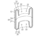
図1は本発明の実施形態1に係る防振装置10の平面図であり、図2は図1のII−II線の断面図である。防振装置10は、自動車のサスペンション用ブッシュとして用いられている。防振装置10は、中空円筒状の金属製の内筒体11と、その内筒体11の外周囲に内筒体11と同軸に配設された中空円筒状の外筒体12と、それら両筒体11,12の間に配設されて、両筒体11,12を互いに連結するゴム弾性体13とを備えている。
(Embodiment 1)
1 is a plan view of a
内筒体11の外周面とゴム弾性体13の内周面とは、互いに接着剤で接着された接着状態である。外筒体12は、樹脂製のものであり、サスペンションリンクの筒部14(図2にのみ図示)内に圧入固定されている。ゴム弾性体13の材料は、例えば天然ゴムである。
The outer peripheral surface of the
ゴム弾性体13の筒軸方向両端面には、筒軸方向外側に向かって開口した、孔部としての1つのすぐり部15がそれぞれ配設されている。各すぐり部15は、ゴム弾性体13の筒軸方向各端部の内筒体11寄りに、筒周方向の全周に亘って連続して設けられている。すなわち、各すぐり部15は、ゴム弾性体13の筒軸方向各端部における筒軸方向の互いに対向する部分に、筒軸方向視で環状に形成されている。各すぐり部15は、ゴム弾性体13の筒軸方向各端面から筒軸方向中央部付近まで延びている。各すぐり部15は、ゴム弾性体13の筒軸方向各端部に内筒体11の外周面との距離が筒軸方向内側から外側に行くに従って大きくなるように設けられている。すなわち、各すぐり部15は、筒軸方向内側から外側に行くに従って筒軸直交方向(筒軸方向と直交する方向。筒径方向)外側に拡開するように形成されている。
On the both end surfaces of the rubber
外筒体12の筒軸方向両端部には、樹脂製の1つのばね体16がそれぞれ配設されている。各ばね体16は、外筒体12と一体に射出成形されている。これら各ばね体16及び外筒体12の材料は、例えばアシアミド、ポリアミド、ナイロン、PPO(ポリフェニレンオキサイド)、ポリエステル等である。
One
各ばね体16は、ゴム弾性体13の筒軸方向各端面の一部を覆う蓋部17と、各すぐり部15に埋設された埋設部18とを有している。
Each
各蓋部17は、外筒体12の筒軸方向各端部に一体に設けられている。各蓋部17は、筒軸方向視で環状に形成されていて、ゴム弾性体13の筒軸方向各端面におけるすぐり部15の外周部に配置されている。各蓋部17の筒軸方向内側面とゴム弾性体13の筒軸方向各端面とは、互いに接着剤で接着されていない非接着状態である。
Each
各埋設部18は、各蓋部17の内周部に一体に設けられている。各埋設部18は、各すぐり部15に筒周方向の全周に亘ってかつ筒軸方向の全域に亘って設けられている。すなわち、各埋設部18は、各すぐり部15の全部を塞ぐように設けられている。各埋設部18は、各すぐり部15の形状に合うように形成されている。すなわち、各埋設部18は、筒軸方向内側から外側に行くに従って筒軸直交方向外側に拡開する中空円錐台(中空略円筒)状に形成されている。各埋設部18の外面と各すぐり部15とは、非接着状態である。
Each embedded
外筒体12及び各ばね体16が樹脂体19を構成している。樹脂体19は、筒軸方向に2等分されていて、第1及び第2分割体20,21からなる。すなわち、外筒体12は、筒軸方向に2等分されており、各ばね体16は、筒軸方向に分割されていない。第1及び第2分割体20,21は、ほぼ同じものである。第1及び第2分割体20,21の外筒体12の筒軸方向外側端部には、1つのばね体16がそれぞれ配設されている。
The outer
−防振装置の製造方法−
以下、図3を参照しながら、本実施形態の防振装置10の製造方法について説明する。
-Manufacturing method of vibration isolator-
Hereinafter, the manufacturing method of the
まず、樹脂射出成形用金型(図示せず)のキャビティに所定の樹脂射出注入孔を介して樹脂を射出注入・充填して、樹脂射出成形用金型を冷却する。樹脂の固化後、樹脂射出成形用金型を離型する。これにより、分割体20が1つ射出成形される。同じ方法で、分割体21をもう1つ成形する(図3(a)を参照)。
First, resin is injected and filled into a cavity of a resin injection mold (not shown) through a predetermined resin injection injection hole, and the resin injection mold is cooled. After the resin is solidified, the resin injection mold is released. Thereby, one divided
次に、内筒体11の外周面に接着剤を塗布する。
Next, an adhesive is applied to the outer peripheral surface of the
次に、内筒体11及び2つの分割体20,21をゴム射出成形用金型(図示せず)のキャビティにセットして、その状態でキャビティに所定のゴム射出注入孔を介してゴムを射出注入・充填して、ゴム射出成形用金型を加熱する。ゴムの加硫後、ゴム射出成形用金型を離型する。これにより、図3(b)に示すように、ゴム弾性体13が射出成形されて、防振装置10が作製される。
Next, the inner
−効果−
以上により、本実施形態によれば、2つの分割体20,21を成形した後、内筒体11及び各分割体20,21をゴム射出成形用金型のキャビティにセットして、その状態でそのキャビティにゴムを射出・充填して、ゴム射出成形用金型を加熱することによって、ゴム弾性体13を射出成形する。このとき、2つの分割体20,21を成形した後、ゴム弾性体13を射出成形するので、ゴム弾性体13は、樹脂の射出成形圧で筒軸直交方向に予備圧縮されない。そのため、ゴム弾性体13の形状の安定性を向上させることができる。
-Effect-
As described above, according to the present embodiment, after the two divided
(実施形態2)
本実施形態は、樹脂体19に、その厚み方向に貫通する複数の貫通孔22,…を配設している点が実施形態1と異なるものである。以下、その相違点について説明する。
(Embodiment 2)
The present embodiment is different from the first embodiment in that a plurality of through
図4に示すように、第1及び第2分割体20,21のばね体16の蓋部17には、複数の貫通孔22,…がそれぞれ形成されている(図4では第1分割体20の貫通孔22のみ図示)。第1分割体20の各貫通孔22と第2分割体21の各貫通孔22とは、樹脂体19の筒軸方向の互いに対向する部分にそれぞれ配設されている。第1及び第2分割体20,21のうち一方の分割体20の各貫通孔22は、ゴム弾性体13の射出成形時に、ゴムを樹脂体19内に射出注入するためのゴム射出注入孔として用いられ、他方の分割体21の各貫通孔22は、ゴム弾性体13の射出成形時に、その各孔22からゴムが出ているかを確認することによって、ゴムが不足しているかを確認するためのゴム不足確認孔として用いられる。以上のように、第1分割体20の各貫通孔22と第2分割体21の各貫通孔22とは、それら貫通孔22をゴム射出注入孔及びゴム不足確認孔としてそれぞれ機能させるため、上述のように樹脂体19にバランス良く配置されている。
As shown in FIG. 4, a plurality of through
−効果−
以上により、本実施形態によれば、樹脂体19に、その厚み方向に貫通する複数の貫通孔22,…を設けているので、ゴム弾性体13の射出成形時に、それら貫通孔22,…を、ゴムを樹脂体19内に射出するためのゴム射出注入孔として用いたり、ゴムが不足しているかを確認するためのゴム不足確認孔として用いたりすることができる。
-Effect-
As described above, according to the present embodiment, since the
なお、本実施形態では、樹脂体19に複数の貫通孔22,…を形成しているが、少なくとも1つの貫通孔22を形成すれば良い。
In the present embodiment, a plurality of through
また、本実施形態では、第1及び第2分割体20,21のばね体16の蓋部17に、複数の貫通孔22,…をそれぞれ形成しているが、これに限らず、例えば、図5に示すように、第1及び第2分割体20,21のばね体16の埋設部18に、複数の貫通孔22,…をそれぞれ形成しても良い。
In the present embodiment, the plurality of through
(実施形態3)
図6に示すように、本実施形態は、第1分割体20の外筒体12の筒軸方向内側端面には、筒軸方向に窪んだ凹部23が筒周方向の全周に亘って連続して設けられており、第2分割体21の外筒体12の筒軸方向内側端面におけるその凹部23に対応する部分には、筒軸方向に突起した凸部24が筒周方向の全周に亘って連続して設けられており、凸部24は、凹部23に嵌合しているものである。その他の点に関しては、実施形態1とほぼ同様の構成である。
(Embodiment 3)
As shown in FIG. 6, in the present embodiment, a concave portion 23 recessed in the cylinder axial direction is continuously provided over the entire circumference in the cylinder circumferential direction on the inner end surface in the cylinder axial direction of the outer
−防振装置の製造方法−
以下、本実施形態の防振装置10の製造方法について説明する。
-Manufacturing method of vibration isolator-
Hereinafter, the manufacturing method of the
まず、第1樹脂射出成形用金型のキャビティに樹脂を射出注入・充填して、第1樹脂射出成形用金型を冷却する。樹脂の固化後、第1樹脂射出成形用金型を離型する。これにより、第1分割体20が射出成形される。
First, resin is injected and filled into the cavity of the first resin injection mold, and the first resin injection mold is cooled. After the resin is solidified, the first resin injection mold is released. Thereby, the
次に、第2樹脂射出成形用金型のキャビティに樹脂を射出注入・充填して、第2樹脂射出成形用金型を冷却する。樹脂の固化後、第2樹脂射出成形用金型を離型する。これにより、第2分割体21が射出成形される。
Next, resin is injected and filled into the cavity of the second resin injection mold, and the second resin injection mold is cooled. After the resin is solidified, the second resin injection mold is released. Thereby, the
次に、内筒体11の外周面に接着剤を塗布する。
Next, an adhesive is applied to the outer peripheral surface of the
次に、第1分割体20の凹部23と第2分割体21の凸部24とを互いに嵌合して、第1分割体20と第2分割体20,21とを互いに組み合わせる。
Next, the recessed part 23 of the
次に、内筒体11並びに予め組み合わせた第1及び第2の分割体20,21をゴム射出成形用金型のキャビティにセットして、その状態でキャビティにゴムを射出注入・充填して、ゴム射出成形用金型を加熱する。ゴムの加硫後、ゴム射出成形用金型を離型する。これにより、ゴム弾性体13が射出成形されて、防振装置10が作製される。
Next, the
−効果−
以上により、本実施形態によれば、第1及び第2分割体20,21のうち一方の分割体20の外筒体12の筒軸方向内側端面に、凹部23を筒周方向の全周に亘って設けており、他方の分割体21の外筒体12の筒軸方向内側端面におけるその凹部23に対応する部分に、凸部24を筒周方向の全周に亘って設けているので、それら凹部23及び凸部24を互いに嵌め合わすことができる。そのため、第1及び第2分割体20,21をゴム射出成形用金型のキャビティにセットする前に、その嵌合を行うことによって、第1及び第2分割体20,21を予め組み合わせた状態でそのキャビティにセットできる。したがって、第1及び第2分割体20,21をそのキャビティに容易にセットできる。
-Effect-
As described above, according to the present embodiment, the concave portion 23 is formed on the entire inner circumference in the cylinder circumferential direction on the inner end surface in the cylinder axis direction of the
なお、本実施形態では、第1分割体20の外筒体12の筒軸方向内側端面に凹部23を設けて、第2分割体21の外筒体12の筒軸方向内側端面に凸部24を設けているが、第2分割体21の外筒体12の筒軸方向内側端面に凹部23を設けて、第1分割体20の外筒体12の筒軸方向内側端面に凸部24を設けても良い。
In the present embodiment, the recess 23 is provided on the inner end surface in the cylinder axis direction of the
(実施形態4)
本実施形態は、ゴム弾性体13の筒軸方向両端部に、ストッパーゴム弾性体25をそれぞれ設けている点等が実施形態1と異なるものである。以下、その相違点について説明する。
(Embodiment 4)
This embodiment is different from the first embodiment in that stopper rubber
図7に示すように、各ばね体16は、ゴム弾性体13の筒軸方向各端部内における外筒体12寄りに埋設されている。各ばね体16の筒軸方向に対する開き角度は、実施形態1のものよりも大きい。各ばね体16の筒軸方向長さは、実施形態1のものよりも短い。
As shown in FIG. 7, each
第1及び第2分割体20,21のばね体16には、複数の貫通孔22,…がそれぞれ形成されている。
A plurality of through
ゴム弾性体13の筒軸方向両端部には、そのゴム弾性体13と一体に成形されたストッパーゴム弾性体25が筒周方向の全周に亘ってそれぞれ配設されている。各ストッパーゴム弾性体25は、各分割体20,21のばね体16の蓋部17の筒軸方向外側面に筒軸方向外側に突出するように配置されている。
Stopper rubber
なお、図7では、サスペンションリンクの筒部14を図示していない。
In FIG. 7, the
−防振装置の製造方法−
以下、本実施形態の防振装置10の製造方法について説明する。
-Manufacturing method of vibration isolator-
Hereinafter, the manufacturing method of the
まず、樹脂射出成形用金型のキャビティに樹脂を射出注入・充填して、樹脂射出成形用金型を冷却する。樹脂の固化後、樹脂射出成形用金型を離型する。これにより、分割体20が1つ射出成形される。同じ方法で、分割体21をもう1つ成形する。
First, resin is injected and filled into the cavity of the resin injection mold, and the resin injection mold is cooled. After the resin is solidified, the resin injection mold is released. Thereby, one divided
次に、内筒体11の外周面に接着剤を塗布する。
Next, an adhesive is applied to the outer peripheral surface of the
次に、内筒体11及び2つの分割体20,21をゴム射出成形用金型のキャビティにセットして、その状態でキャビティにゴムを射出注入・充填して、ゴム射出成形用金型を加熱する。ゴムの加硫後、ゴム射出成形用金型を離型する。これにより、ゴム弾性体13とストッパーゴム弾性体25とが一体に射出成形されて、防振装置10が作製される。
Next, the
−効果−
以上により、本実施形態によれば、ゴム弾性体13の筒軸方向両端部に、そのゴム弾性体13と一体に成形されたストッパーゴム弾性体25を筒軸方向外側に突出するようにそれぞれ設けているので、そのストッパーゴム弾性体25によって、両筒体11,12の筒軸方向の相対移動を規制できる。
-Effect-
As described above, according to the present embodiment, the stopper rubber
なお、本実施形態では、ゴム弾性体13の筒軸方向両端部に、ストッパーゴム弾性体25をそれぞれ配設しているが、ゴム弾性体13の筒軸方向一端部に、ストッパーゴム弾性体25を配設しても良い。
In this embodiment, the stopper rubber
(実施形態5)
本実施形態は、ゴム射出成形用金型26の構成等が実施形態1と相違するものである。以下、その相違点について説明する。
(Embodiment 5)
In the present embodiment, the configuration of the
各すぐり部15は、ゴム弾性体13の筒軸方向各端面における外筒体12寄りに開口している(図8を参照)。各ばね体16の埋設部18の筒軸方向に対する開き角度は、実施形態1のものよりも大きい。各ばね体16の埋設部18の筒軸方向長さは、実施形態1のものよりも短い。
Each curling
第1及び第2分割体20,21の外筒体12の筒軸方向内側端面の間には、後述する中型26cの筒軸方向長さ(厚さ)とほぼ同じ大きさの所定の間隔があいている(図8を参照)。言い換えると、外筒体12の筒軸方向中央部には、切欠き部27が筒周方向の全周に亘って設けられている。
Between the inner end surfaces of the
−防振装置の製造方法−
以下、図8を参照しながら、本実施形態の防振装置10の製造方法について説明する。
-Manufacturing method of vibration isolator-
Hereinafter, the manufacturing method of the
ここで、本実施形態のゴム射出成形用金型26は、筒軸方向に窪んで開口断面の一部が円状の凹部が設けられ、ゴム弾性体13の筒軸方向一方側をゴム成形するための上型26aと、ゴム弾性体13のゴム成形時に、その上型26aと対向するように配置されるとともに、筒軸方向に窪んで開口断面の一部が円状の凹部が設けられ、かつ、ゴム弾性体13の筒軸方向他方側をゴム成形するための下型26bと、ゴム弾性体13のゴム成形時に、それら両型26a,26b間に配置され、筒軸方向に貫通して開口断面が円状の開口部が設けられた中型26cとを有している。上型26a及び下型26bの開口断面積は、中型26cの開口断面積よりも大きい。すなわち、上型26a及び下型26bの内径は、中型26cの内径よりも大きい。
Here, the
まず、樹脂射出成形用金型のキャビティに樹脂を射出注入・充填して、樹脂射出成形用金型を冷却する。樹脂の固化後、樹脂射出成形用金型を離型する。これにより、分割体20が1つ射出成形される。同じ方法で、分割体21をもう1つ成形する。
First, resin is injected and filled into the cavity of the resin injection mold, and the resin injection mold is cooled. After the resin is solidified, the resin injection mold is released. Thereby, one divided
次に、内筒体11の外周面に接着剤を塗布する。
Next, an adhesive is applied to the outer peripheral surface of the
次に、内筒体11及び2つの分割体20,21をゴム射出成形用金型26のキャビティにセットする。このとき、中型26cは、内周部が両分割体20,21の外筒体12の筒軸方向内側端面の間に介在するように配置される。その状態でキャビティにゴムを射出注入・充填して、ゴム射出成形用金型26を加熱する。ゴムの加硫後、ゴム射出成形用金型26を離型する。これにより、ゴム弾性体13が射出成形されて、防振装置10が作製される。
Next, the
−効果−
以上により、本実施形態によれば、ゴム射出成形用金型26は、上型26aと、下型26bと、ゴム弾性体13の射出成形時に、それら両型26a,26bの間に内周部が第1及び第2分割体20,21の外筒体12の筒軸方向内側端面の間に挟まれるように配置される中型26cとを有するので、ゴム弾性体13の射出成形時に、ゴム射出成形用金型26のキャビティに射出・充填されたゴムと中型26cとを互いに接した状態にすることができる。そのため、熱を中型26cを介してそのキャビティに射出・充填されたゴムに十分に伝えることができる。したがって、そのキャビティに射出・充填されたゴムへの熱伝導性を向上させることができる。
-Effect-
As described above, according to the present embodiment, the
(その他の実施形態)
上記各実施形態では、防振装置10は、自動車のサスペンション用ブッシュとして用いられているが、これに限らず、自動車のサスペンション用以外にも、軸直剛性を高くしたいという要求があれば、どのようなブッシュにも適用できる。
(Other embodiments)
In each of the above-described embodiments, the
また、上記各実施形態では、内筒体11は金属製のものであるが、これに限らず、例えば樹脂製のものであっても良い。
Moreover, in each said embodiment, although the
また、上記各実施形態では、すぐり部15を、ゴム弾性体13の筒軸方向各端部に筒周方向の全周に亘って設けており、ばね体16を、ゴム弾性体13の筒軸方向各端部のすぐり部15に筒周方向の全周に亘って設けているが、ゴム弾性体13の筒軸方向各端部に、少なくとも1つのすぐり部15を筒周方向の少なくとも一部に亘って設けて、ゴム弾性体13の筒軸方向各端部の少なくとも1つのすぐり部15に、少なくとも1つのばね体16を筒周方向の少なくとも一部に亘って設ければ良い。
Further, in each of the above embodiments, the
また、上記各実施形態では、すぐり部15を、ゴム弾性体13の筒軸方向各端部に内筒体11の外周面との距離が筒軸方向内側から外側に行くに従って大きくなるように設けているが、これに限らず、例えば外筒体12の外周面との距離が筒軸方向内側から外側に亘って同じ大きさになるように設けても良い。
Further, in each of the above embodiments, the
また、上記各実施形態では、内筒体11の外周面と各ばね体16の内周面との間に、ゴム弾性体13を設けているが、ゴム弾性体13を設けなくても良い。すなわち、内筒体11の外周面と各ばね体16の埋設部18の内周面との間に、空間部を形成しても良い。さらに、ゴム弾性体13を設けない場合、各ばね体16を内筒体11の外周面に接触させても良い。
Moreover, in each said embodiment, although the rubber
また、上記各実施形態では、内筒体11の外周面とゴム弾性体13の内周面とを、接着状態にしているが、それを非接着状態にしても良い。
Moreover, in each said embodiment, although the outer peripheral surface of the
また、上記各実施形態では、各ばね体16の蓋部17の筒軸方向内側面とゴム弾性体13の筒軸方向各端面とを、非接着状態にし、各ばね体16の埋設部18の外面と各すぐり部15とを、非接着状態にしているが、それらをそれぞれ接着状態にしても良い。
Moreover, in each said embodiment, the cylinder axial direction inner surface of the
また、上記各実施形態では、第1及び第2分割体20,21は、ほぼ同じもの又は近似したものであるが、異なったものでも良い。例えば、第1及び第2分割体20,21は、外筒体12の筒軸方向長さが異なったものでも良い。
Moreover, in each said embodiment, although the 1st and
また、上記各実施形態では、樹脂体19は、第1及び第2分割体20,21からなるが、これに限らず、3つ以上の分割体からなっても良い。この場合、筒軸方向の最も外側に位置する2つの分割体にばね体16をそれぞれ設けるのが好ましい。
Moreover, in each said embodiment, although the
また、上記各実施形態では、外筒体12及び各ばね体16が樹脂体19を構成しているが、少なくとも外筒体12及び各ばね体16が樹脂体19を構成すれば良い。すなわち、外筒体12及び各ばね体16に加えて、樹脂製のその他の構成体も樹脂体19を構成しても良い。但し、この構成体は、外筒体12及び各ばね体16と一体に成形される必要がある。
Moreover, in each said embodiment, although the
本発明は、実施形態に限定されず、その精神又は主要な特徴から逸脱することなく他の色々な形で実施することができる。 The present invention is not limited to the embodiments, and can be implemented in various other forms without departing from the spirit or main features thereof.
このように、上述の実施形態はあらゆる点で単なる例示に過ぎず、限定的に解釈してはならない。本発明の範囲は請求の範囲によって示すものであって、明細書本文には何ら拘束されない。さらに、請求の範囲の均等範囲に属する変形や変更は、全て本発明の範囲内のものである。 As described above, the above-described embodiment is merely an example in all respects and should not be interpreted in a limited manner. The scope of the present invention is indicated by the claims, and is not restricted by the text of the specification. Further, all modifications and changes belonging to the equivalent scope of the claims are within the scope of the present invention.
以上説明したように、本発明は、内筒体と、該内筒体の外周囲に内筒体と同軸に設けられた樹脂製の外筒体と、該両筒体の間に設けられ、上記両筒体を互いに連結するゴム弾性体とを備えた防振装置等について有用である。 As described above, the present invention is provided between the inner cylinder, the resin outer cylinder provided coaxially with the inner cylinder on the outer periphery of the inner cylinder, and both the cylinders, It is useful for a vibration isolator provided with a rubber elastic body that connects the two cylinders to each other.
10 防振装置
11 内筒体
12 外筒体
13 ゴム弾性体
14 サスペンションリンクの筒部
15 すぐり部(孔部)
16 ばね体
17 蓋部
18 埋設部
19 樹脂体
20 第1分割体
21 第2分割体
22 貫通孔
23 凹部
24 凸部
25 ストッパーゴム弾性体
26 ゴム射出成形用金型
26a 上型
26b 下型
26c 中型
DESCRIPTION OF
16
Claims (9)
上記ゴム弾性体の筒軸方向両端部には、少なくとも1つの孔部が筒周方向の少なくとも一部に亘ってそれぞれ設けられており、
上記ゴム弾性体の筒軸方向各端部の少なくとも1つの孔部には、上記外筒体と一体に成形された少なくとも1つの樹脂製のばね体が筒周方向の少なくとも一部に亘って設けられており、
少なくとも上記外筒体及び上記各ばね体が樹脂体を構成しており、
上記樹脂体は、筒軸方向に複数に分割されていて、該複数の分割体からなることを特徴とする防振装置。 An inner cylinder, a resin-made outer cylinder provided coaxially with the inner cylinder on the outer periphery of the inner cylinder, and a rubber elasticity provided between the two cylinders and connecting the two cylinders to each other An anti-vibration device comprising a body,
At least one hole is provided over at least a part of the cylinder circumferential direction at both ends in the cylinder axial direction of the rubber elastic body,
At least one hole at each end in the cylinder axial direction of the rubber elastic body is provided with at least one resin spring body formed integrally with the outer cylinder over at least a part in the cylinder circumferential direction. And
At least the outer cylinder body and the spring bodies constitute a resin body,
The anti-vibration device according to claim 1, wherein the resin body is divided into a plurality of parts in the cylinder axis direction and includes the plurality of divided bodies.
上記樹脂体は、筒軸方向に2分割されていて、第1及び第2分割体からなることを特徴とする防振装置。 The vibration isolator according to claim 1, wherein
The anti-vibration device according to claim 1, wherein the resin body is divided into two in the cylinder axis direction, and includes the first and second divided bodies.
上記第1及び第2分割体のうち一方の分割体の外筒体の筒軸方向内側端面には、凹部が筒周方向の全周に亘って設けられており、
他方の分割体の外筒体の筒軸方向内側端面における該凹部に対応する部分には、凸部が筒周方向の全周に亘って設けられていることを特徴とする防振装置。 The vibration isolator according to claim 2,
A concave portion is provided over the entire circumference in the cylinder circumferential direction on the inner end surface in the cylinder axial direction of the outer cylinder of one of the first and second divided bodies.
A vibration isolator, wherein a convex portion is provided over the entire circumference in the cylinder circumferential direction at a portion corresponding to the concave portion on the inner axial end surface of the outer cylinder of the other divided body.
上記第1及び第2分割体の外筒体の筒軸方向内側端面の間には、所定の間隔があいていることを特徴とする防振装置。 The vibration isolator according to claim 2,
A vibration isolator having a predetermined distance between the inner end surfaces in the cylinder axis direction of the outer cylinders of the first and second divided bodies.
上記孔部は、上記ゴム弾性体の筒軸方向各端部に筒周方向の全周に亘って設けられた1つの孔部で構成されており、
上記ばね体は、上記ゴム弾性体の筒軸方向各端部の孔部に筒周方向の全周に亘って設けられた1つのばね体で構成されていることを特徴とする防振装置。 In the vibration isolator as described in any one of Claims 1-4,
The hole is composed of one hole provided at each end in the cylinder axial direction of the rubber elastic body over the entire circumference in the cylinder circumferential direction,
The anti-vibration device according to claim 1, wherein the spring body is constituted by a single spring body provided in a hole at each end of the rubber elastic body in the cylinder axial direction over the entire circumference in the cylinder circumferential direction.
上記樹脂体には、その厚み方向に貫通する少なくとも1つの貫通孔が設けられていることを特徴とする防振装置。 In the vibration isolator as described in any one of Claims 1-5,
The vibration isolator, wherein the resin body is provided with at least one through hole penetrating in the thickness direction.
上記ゴム弾性体の筒軸方向両端部のうち少なくとも一方の端部には、該ゴム弾性体と一体に成形されたストッパーゴム弾性体が筒軸方向外側に突出するように設けられていることを特徴とする防振装置。 In the vibration isolator as described in any one of Claims 1-6,
A stopper rubber elastic body formed integrally with the rubber elastic body is provided at at least one of the both ends in the cylinder axial direction of the rubber elastic body so as to protrude outward in the cylinder axial direction. Anti-vibration device characterized.
上記複数の分割体を成形する工程と、
上記内筒体及び上記各分割体をゴム射出成形用金型のキャビティにセットして、その状態で該キャビティにゴムを射出・充填して、上記ゴム射出成形用金型を加熱することによって、上記ゴム弾性体を射出成形する工程とを備えたことを特徴とする防振装置の製造方法。 It is a manufacturing method of the vibration isolator of Claim 1, Comprising:
Forming the plurality of divided bodies;
By setting the inner cylindrical body and each of the divided bodies in a cavity of a rubber injection mold, injecting and filling rubber into the cavity in that state, and heating the rubber injection mold, And a step of injection-molding the rubber elastic body.
上記樹脂体は、筒軸方向に2分割されていて、第1及び第2分割体からなっており、
上記ゴム射出成形用金型は、上型と、下型と、上記ゴム弾性体の射出成形時に、該両型の間に内周部が上記第1及び第2分割体の外筒体の筒軸方向内側端面の間に挟まれるように配置される中型とを有することを特徴とする防振装置の製造方法。 In the manufacturing method of the vibration isolator of Claim 8,
The resin body is divided into two in the cylinder axis direction, and is composed of first and second divided bodies,
The rubber injection mold includes an upper cylinder, a lower mold, and an outer cylinder of the first and second divided bodies whose inner peripheral portion is between the molds when the rubber elastic body is injection molded. A vibration isolator manufacturing method comprising: an intermediate mold disposed so as to be sandwiched between axially inner end faces.
Priority Applications (1)
| Application Number | Priority Date | Filing Date | Title |
|---|---|---|---|
| JP2005265681A JP4471908B2 (en) | 2005-09-13 | 2005-09-13 | Vibration isolator and manufacturing method thereof |
Applications Claiming Priority (1)
| Application Number | Priority Date | Filing Date | Title |
|---|---|---|---|
| JP2005265681A JP4471908B2 (en) | 2005-09-13 | 2005-09-13 | Vibration isolator and manufacturing method thereof |
Publications (2)
| Publication Number | Publication Date |
|---|---|
| JP2007078050A JP2007078050A (en) | 2007-03-29 |
| JP4471908B2 true JP4471908B2 (en) | 2010-06-02 |
Family
ID=37938590
Family Applications (1)
| Application Number | Title | Priority Date | Filing Date |
|---|---|---|---|
| JP2005265681A Expired - Lifetime JP4471908B2 (en) | 2005-09-13 | 2005-09-13 | Vibration isolator and manufacturing method thereof |
Country Status (1)
| Country | Link |
|---|---|
| JP (1) | JP4471908B2 (en) |
Families Citing this family (2)
| Publication number | Priority date | Publication date | Assignee | Title |
|---|---|---|---|---|
| US8967599B2 (en) | 2011-03-31 | 2015-03-03 | Honda Motor Co., Ltd. | Torque arm for automobile |
| CN113864391B (en) * | 2021-09-28 | 2023-04-07 | 深圳市火乐科技发展有限公司 | Elastic support piece, vibration reduction design method and projection equipment |
-
2005
- 2005-09-13 JP JP2005265681A patent/JP4471908B2/en not_active Expired - Lifetime
Also Published As
| Publication number | Publication date |
|---|---|
| JP2007078050A (en) | 2007-03-29 |
Similar Documents
| Publication | Publication Date | Title |
|---|---|---|
| JP5476247B2 (en) | Silencer for laminated leaf spring | |
| JP4046093B2 (en) | Manufacturing method of resin torque rod | |
| JP4833128B2 (en) | Anti-vibration bush and manufacturing method thereof | |
| JP6381450B2 (en) | Mounting structure for internal parts of automobile fuel tank | |
| JP4794004B2 (en) | Anti-vibration bush | |
| JP2009503416A (en) | Friction plate and various manufacturing methods thereof | |
| JP4471908B2 (en) | Vibration isolator and manufacturing method thereof | |
| JP2018132133A (en) | Torque rod and manufacturing method thereof | |
| CN110325757A (en) | Elastic support | |
| JP4511438B2 (en) | Vibration isolator and manufacturing method thereof | |
| JP5968043B2 (en) | Vibration isolator and manufacturing method thereof | |
| JP4032537B2 (en) | Plastic fuel delivery pipe | |
| JP5358323B2 (en) | Anti-vibration device manufacturing method | |
| JP5391114B2 (en) | Vibration isolator set and manufacturing method thereof | |
| JP4471909B2 (en) | Vibration isolator | |
| JP2008519945A (en) | Method for producing an elastomer bearing, sleeve bearing produced thereby and apparatus for producing the same | |
| JP4413028B2 (en) | Vibration isolator and manufacturing method thereof | |
| JP2003247593A (en) | Dynamic damper manufacturing method | |
| JP2012197910A (en) | Dynamic dumper | |
| JP2008163986A (en) | Anti-vibration bush | |
| KR101536687B1 (en) | Manufacturing method for pillow ball joint | |
| JP2002276712A (en) | bush | |
| JP3454588B2 (en) | Manufacturing method of vibration isolator | |
| JP6534608B2 (en) | Vibration control device | |
| JP2007040394A (en) | Bumper rubber and bumper rubber manufacturing method |
Legal Events
| Date | Code | Title | Description |
|---|---|---|---|
| A621 | Written request for application examination |
Free format text: JAPANESE INTERMEDIATE CODE: A621 Effective date: 20080714 |
|
| A977 | Report on retrieval |
Free format text: JAPANESE INTERMEDIATE CODE: A971007 Effective date: 20100201 |
|
| TRDD | Decision of grant or rejection written | ||
| A01 | Written decision to grant a patent or to grant a registration (utility model) |
Free format text: JAPANESE INTERMEDIATE CODE: A01 Effective date: 20100216 |
|
| A01 | Written decision to grant a patent or to grant a registration (utility model) |
Free format text: JAPANESE INTERMEDIATE CODE: A01 |
|
| A61 | First payment of annual fees (during grant procedure) |
Free format text: JAPANESE INTERMEDIATE CODE: A61 Effective date: 20100302 |
|
| FPAY | Renewal fee payment (event date is renewal date of database) |
Free format text: PAYMENT UNTIL: 20130312 Year of fee payment: 3 |
|
| R150 | Certificate of patent or registration of utility model |
Free format text: JAPANESE INTERMEDIATE CODE: R150 |