JP4582001B2 - 軸心合わせ方法 - Google Patents
軸心合わせ方法 Download PDFInfo
- Publication number
- JP4582001B2 JP4582001B2 JP2006002237A JP2006002237A JP4582001B2 JP 4582001 B2 JP4582001 B2 JP 4582001B2 JP 2006002237 A JP2006002237 A JP 2006002237A JP 2006002237 A JP2006002237 A JP 2006002237A JP 4582001 B2 JP4582001 B2 JP 4582001B2
- Authority
- JP
- Japan
- Prior art keywords
- shaft
- hole
- spindle
- motor
- coupling
- Prior art date
- Legal status (The legal status is an assumption and is not a legal conclusion. Google has not performed a legal analysis and makes no representation as to the accuracy of the status listed.)
- Expired - Lifetime
Links
Images




Classifications
-
- F—MECHANICAL ENGINEERING; LIGHTING; HEATING; WEAPONS; BLASTING
- F16—ENGINEERING ELEMENTS AND UNITS; GENERAL MEASURES FOR PRODUCING AND MAINTAINING EFFECTIVE FUNCTIONING OF MACHINES OR INSTALLATIONS; THERMAL INSULATION IN GENERAL
- F16D—COUPLINGS FOR TRANSMITTING ROTATION; CLUTCHES; BRAKES
- F16D1/00—Couplings for rigidly connecting two coaxial shafts or other movable machine elements
- F16D1/06—Couplings for rigidly connecting two coaxial shafts or other movable machine elements for attachment of a member on a shaft or on a shaft-end
- F16D1/08—Couplings for rigidly connecting two coaxial shafts or other movable machine elements for attachment of a member on a shaft or on a shaft-end with clamping hub; with hub and longitudinal key
- F16D1/0852—Couplings for rigidly connecting two coaxial shafts or other movable machine elements for attachment of a member on a shaft or on a shaft-end with clamping hub; with hub and longitudinal key with radial clamping between the mating surfaces of the hub and shaft
- F16D1/0864—Couplings for rigidly connecting two coaxial shafts or other movable machine elements for attachment of a member on a shaft or on a shaft-end with clamping hub; with hub and longitudinal key with radial clamping between the mating surfaces of the hub and shaft due to tangential loading of the hub, e.g. a split hub
-
- F—MECHANICAL ENGINEERING; LIGHTING; HEATING; WEAPONS; BLASTING
- F16—ENGINEERING ELEMENTS AND UNITS; GENERAL MEASURES FOR PRODUCING AND MAINTAINING EFFECTIVE FUNCTIONING OF MACHINES OR INSTALLATIONS; THERMAL INSULATION IN GENERAL
- F16D—COUPLINGS FOR TRANSMITTING ROTATION; CLUTCHES; BRAKES
- F16D3/00—Yielding couplings, i.e. with means permitting movement between the connected parts during the drive
- F16D3/50—Yielding couplings, i.e. with means permitting movement between the connected parts during the drive with the coupling parts connected by one or more intermediate members
- F16D3/78—Yielding couplings, i.e. with means permitting movement between the connected parts during the drive with the coupling parts connected by one or more intermediate members shaped as an elastic disc or flat ring, arranged perpendicular to the axis of the coupling parts, different sets of spots of the disc or ring being attached to each coupling part, e.g. Hardy couplings
- F16D3/79—Yielding couplings, i.e. with means permitting movement between the connected parts during the drive with the coupling parts connected by one or more intermediate members shaped as an elastic disc or flat ring, arranged perpendicular to the axis of the coupling parts, different sets of spots of the disc or ring being attached to each coupling part, e.g. Hardy couplings the disc or ring being metallic
Landscapes
- Engineering & Computer Science (AREA)
- General Engineering & Computer Science (AREA)
- Mechanical Engineering (AREA)
- Connection Of Motors, Electrical Generators, Mechanical Devices, And The Like (AREA)
Description
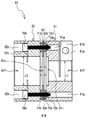
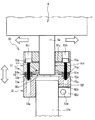
また、駆動側ハブと従動側ハブとの間隙に設けられて各々を連結する板バネを備え、第1回転軸と第2回転軸とが同芯となると、第2回転軸は第2貫通孔及び第3貫通孔を貫通して穴部に嵌合可能となる。よって、駆動側ハブ及び従動側ハブを連結する板バネが、回転駆動時における回転軸の軸ズレを吸収するとともに、駆動部側から従動部側に伝達する熱を遮断するため、回転駆動時における性能劣化を防止することができる。
また、駆動側ハブと従動側ハブとの間隙に設けられて各々を連結する板バネを備え、モータ軸とスピンドル軸とが同芯となると、スピンドル軸は第2貫通孔及び第3貫通孔を貫通して穴部に嵌合可能となる。よって、駆動側ハブ及び従動側ハブを連結する板バネが、回転駆動時における回転軸の軸ズレを吸収するとともに、主軸モータ側から主軸側に伝達する熱を遮断するため、回転駆動時における性能劣化を防止することができる。
6 工具
7 主軸ヘッド
8 主軸モータ
8a モータ軸
9 主軸
27 スピンドル
27a スピンドル軸
50 カップリング
51 モータ側ハブ
51f モータ軸穴
51i 軸心合わせ穴
52 スピンドル側ハブ
52f スピンドル軸穴
53 板バネ
53c 軸挿脱穴
70a 連結ボルト
70b 連結ボルト
71a ワッシャ
71b ワッシャ
72a ワッシャ
72b ワッシャ
73a 連結ナット
73b 連結ナット
Claims (2)
- 駆動部の第1回転軸を挿脱可能な第1貫通孔が形成された駆動側ハブと、前記第1回転軸よりも径が大きい従動部の第2回転軸を挿脱可能な第2貫通孔が形成された従動側ハブとを備えたカップリングを用いて、前記駆動部の第1回転軸と前記従動部の第2回転軸とを同芯となるように連結するための軸心合わせ方法であって、
前記カップリングは、
前記駆動側ハブと前記従動側ハブとの間隙に設けられ、前記駆動側ハブおよび前記従動側ハブを連結するとともに、少なくとも前記第2回転軸を挿脱可能な第3貫通孔が中心部に形成された板バネを備え、
前記駆動側ハブにおける前記従動側ハブと対向する面には、前記第1貫通孔において前記第1回転軸が挿脱される一端側の開口部とは異なる他端側の開口部が形成されるとともに、前記他端側の開口部は前記第2貫通孔と同径となるように拡径した穴部であり、
前記第1貫通孔に挿入された前記第1回転軸と前記第2貫通孔に挿入された前記第2回転軸とが同芯となると、前記第2回転軸は前記第2貫通孔及び前記第3貫通孔を介して前記穴部に嵌合可能となり、
前記軸心合わせ方法は、
前記駆動部と前記従動部とを前記カップリングを介して互いに取り付けて、前記第1回転軸を前記第1貫通孔に挿入させる一方、前記第2回転軸を前記第2貫通孔に挿入させる回転軸挿入工程と、
前記カップリングを前記第1回転軸及び前記第2回転軸の軸線方向に移動させる一方、前記駆動部及び前記従動部の少なくとも一方を該軸線方向と直交する方向に移動させて、前記第2回転軸を前記第2貫通孔及び前記第3貫通孔を介して前記穴部に嵌合させる穴部嵌合工程と、
前記駆動部及び前記従動部を固定する動部固定工程と、
前記カップリングを前記第1回転軸及び前記第2回転軸の軸線方向に移動させて、前記第1回転軸を前記駆動側ハブに位置決めする一方、第2回転軸を前記従動側ハブに位置決めする回転軸位置決め工程と、
前記第1回転軸を前記駆動側ハブに固定する一方、前記第2回転軸を前記従動側ハブに固定するカップリング固定工程とを備えたことを特徴とする軸心合わせ方法。 - 主軸モータのモータ軸と、主軸内部に設けられて前記モータ軸よりも径が大きいスピンドル軸と、前記モータ軸および前記スピンドル軸を連結するカップリングとを備えた工作機械において、前記カップリングを用いて前記モータ軸と前記スピンドル軸とを同芯となるように連結するための軸心合わせ方法であって、
前記カップリングは、
前記モータ軸を挿脱可能な第1貫通孔が形成された駆動側ハブと、
前記スピンドル軸を挿脱可能な第2貫通孔が形成された従動側ハブと、
前記駆動側ハブと前記従動側ハブとの間隙に設けられ、前記駆動側ハブおよび前記従動側ハブを連結するとともに、少なくとも前記スピンドル軸を挿脱可能な第3貫通孔が中心部に形成された板バネとを備え、
前記駆動側ハブにおける前記従動側ハブと対向する面には、前記第1貫通孔において前記モータ軸が挿脱される一端側の開口部とは異なる他端側の開口部が形成されるとともに、前記他端側の開口部は前記第2貫通孔と同径となるように拡径した穴部であり、
前記第1貫通孔に挿入された前記モータ軸と前記第2貫通孔に挿入された前記スピンドル軸とが同芯となると、前記スピンドル軸は前記第2貫通孔及び前記第3貫通孔を介して前記穴部に嵌合可能となり、
前記軸心合わせ方法は、
前記主軸モータを前記主軸に前記カップリングを介して取り付けて、前記モータ軸を前記第1貫通孔に挿入させる一方、前記スピンドル軸を前記第2貫通孔に挿入させる回転軸挿入工程と、
前記カップリングを前記モータ軸及び前記スピンドル軸の軸線方向に移動させる一方、前記主軸モータを該軸線方向と直交する方向に移動させて、前記スピンドル軸を前記第2貫通孔及び前記第3貫通孔を介して前記穴部に嵌合させる穴部嵌合工程と、
前記主軸モータを固定するモータ固定工程と、
前記カップリングを前記モータ軸及び前記スピンドル軸の軸線方向に移動させて、前記モータ軸を前記駆動側ハブに位置決めする一方、前記スピンドル軸を前記従動側ハブに位置決めする回転軸位置決め工程と、
前記モータ軸を前記駆動側ハブに固定する一方、前記スピンドル軸を前記従動側ハブに固定するカップリング固定工程とを備えたことを特徴とする軸心合わせ方法。
Priority Applications (1)
| Application Number | Priority Date | Filing Date | Title |
|---|---|---|---|
| JP2006002237A JP4582001B2 (ja) | 2006-01-10 | 2006-01-10 | 軸心合わせ方法 |
Applications Claiming Priority (1)
| Application Number | Priority Date | Filing Date | Title |
|---|---|---|---|
| JP2006002237A JP4582001B2 (ja) | 2006-01-10 | 2006-01-10 | 軸心合わせ方法 |
Publications (2)
| Publication Number | Publication Date |
|---|---|
| JP2007182947A JP2007182947A (ja) | 2007-07-19 |
| JP4582001B2 true JP4582001B2 (ja) | 2010-11-17 |
Family
ID=38339214
Family Applications (1)
| Application Number | Title | Priority Date | Filing Date |
|---|---|---|---|
| JP2006002237A Expired - Lifetime JP4582001B2 (ja) | 2006-01-10 | 2006-01-10 | 軸心合わせ方法 |
Country Status (1)
| Country | Link |
|---|---|
| JP (1) | JP4582001B2 (ja) |
Families Citing this family (6)
| Publication number | Priority date | Publication date | Assignee | Title |
|---|---|---|---|---|
| JP2015134072A (ja) * | 2014-01-17 | 2015-07-27 | Hoya株式会社 | 内視鏡用光源装置における回転チョッパ駆動装置、及び、内視鏡用光源装置における回転チョッパ駆動装置の組立方法 |
| CN105071613B (zh) * | 2015-09-07 | 2017-10-03 | 环宇平 | 多功能轨迹调节盘 |
| JP2018184984A (ja) * | 2017-04-25 | 2018-11-22 | 株式会社荏原製作所 | 芯出し治具及び芯出し方法 |
| SG10201705006WA (en) * | 2017-06-16 | 2018-09-27 | Stamford Prec Tools Pte Ltd | Precision securing device |
| CN114932464B (zh) * | 2022-06-02 | 2023-07-25 | 无锡鸿海龙船机有限公司 | 一种船用联轴器及其抛光打磨感应定位夹具 |
| CN115324839B (zh) * | 2022-09-13 | 2025-08-05 | 中国船舶重工集团海装风电股份有限公司 | 一种串列式双风轮风电机组、传动链及安装方法 |
Family Cites Families (2)
| Publication number | Priority date | Publication date | Assignee | Title |
|---|---|---|---|---|
| JPH0165930U (ja) * | 1987-10-21 | 1989-04-27 | ||
| JP2001349335A (ja) * | 2000-06-07 | 2001-12-21 | Daido Seimitsu Kogyo Kk | フレキシブル継手 |
-
2006
- 2006-01-10 JP JP2006002237A patent/JP4582001B2/ja not_active Expired - Lifetime
Also Published As
| Publication number | Publication date |
|---|---|
| JP2007182947A (ja) | 2007-07-19 |
Similar Documents
| Publication | Publication Date | Title |
|---|---|---|
| US7987567B2 (en) | Machine tool | |
| US8950987B2 (en) | Method of boring work by 5-axis machining double-housing machine tool and 5-axis machining double-housing machine tool | |
| JP2008264891A (ja) | ユニバーサルヘッドおよびこれを有する工作機械 | |
| US20110268520A1 (en) | Angle tool holder for five-face machining | |
| JP4582001B2 (ja) | 軸心合わせ方法 | |
| JP2020040202A (ja) | タレット旋盤用工具ホルダ | |
| US20110058913A1 (en) | Tool head for use in a multiaxis machine, multiaxis machine having such a tool head, and use of such a machine | |
| KR200490860Y1 (ko) | 공작 기계 | |
| US20050271488A1 (en) | Machine tool for working ring-shaped workpieces | |
| CN100421878C (zh) | 通用和标准组件的工件保持装置 | |
| JP2008298212A (ja) | ギヤヘッド | |
| JPWO2014097434A1 (ja) | 工作機械の内径旋削アタッチメント | |
| TW202239516A (zh) | 工具機 | |
| JP5728316B2 (ja) | 多軸工作機械 | |
| CN114800051A (zh) | 机床 | |
| JP2012161904A (ja) | 複合工具、加工方法および工作機械 | |
| JP4700590B2 (ja) | 横形マシンニングセンタ | |
| KR100671021B1 (ko) | 포터블 보링 머신 | |
| KR20210148663A (ko) | 가공물 고정 장치 | |
| JPH1015703A (ja) | 多機能旋盤 | |
| CN216370286U (zh) | 一种六轴微孔加工中心 | |
| JP2020182991A (ja) | 工作機械 | |
| CN220217462U (zh) | 快速转换的多功能钻铆装置 | |
| JP3348106B2 (ja) | 門型複合加工機 | |
| CN221312564U (zh) | 一种钻孔深度限位摇臂钻床 |
Legal Events
| Date | Code | Title | Description |
|---|---|---|---|
| RD04 | Notification of resignation of power of attorney |
Free format text: JAPANESE INTERMEDIATE CODE: A7424 Effective date: 20080223 |
|
| A621 | Written request for application examination |
Free format text: JAPANESE INTERMEDIATE CODE: A621 Effective date: 20080313 |
|
| A977 | Report on retrieval |
Free format text: JAPANESE INTERMEDIATE CODE: A971007 Effective date: 20091015 |
|
| A131 | Notification of reasons for refusal |
Free format text: JAPANESE INTERMEDIATE CODE: A131 Effective date: 20091027 |
|
| A521 | Request for written amendment filed |
Free format text: JAPANESE INTERMEDIATE CODE: A523 Effective date: 20091225 |
|
| TRDD | Decision of grant or rejection written | ||
| A01 | Written decision to grant a patent or to grant a registration (utility model) |
Free format text: JAPANESE INTERMEDIATE CODE: A01 Effective date: 20100803 |
|
| A01 | Written decision to grant a patent or to grant a registration (utility model) |
Free format text: JAPANESE INTERMEDIATE CODE: A01 |
|
| A61 | First payment of annual fees (during grant procedure) |
Free format text: JAPANESE INTERMEDIATE CODE: A61 Effective date: 20100816 |
|
| R150 | Certificate of patent or registration of utility model |
Ref document number: 4582001 Country of ref document: JP Free format text: JAPANESE INTERMEDIATE CODE: R150 Free format text: JAPANESE INTERMEDIATE CODE: R150 |
|
| FPAY | Renewal fee payment (event date is renewal date of database) |
Free format text: PAYMENT UNTIL: 20130910 Year of fee payment: 3 |