JP4732409B2 - 自動二輪車におけるオイルレベル確認構造 - Google Patents
自動二輪車におけるオイルレベル確認構造 Download PDFInfo
- Publication number
- JP4732409B2 JP4732409B2 JP2007230673A JP2007230673A JP4732409B2 JP 4732409 B2 JP4732409 B2 JP 4732409B2 JP 2007230673 A JP2007230673 A JP 2007230673A JP 2007230673 A JP2007230673 A JP 2007230673A JP 4732409 B2 JP4732409 B2 JP 4732409B2
- Authority
- JP
- Japan
- Prior art keywords
- oil level
- engine
- level gauge
- oil
- fuel tank
- Prior art date
- Legal status (The legal status is an assumption and is not a legal conclusion. Google has not performed a legal analysis and makes no representation as to the accuracy of the status listed.)
- Expired - Fee Related
Links
Images


Landscapes
- Lubrication Details And Ventilation Of Internal Combustion Engines (AREA)
Description
12・・・フロントフォーク
12a・・・トップブリッジ
14・・・エンジン本体
15・・・燃料タンク
16・・・乗車用シート
25・・・エンジンカバー
25a,25b・・・膨出部
26・・・回転軸であるクランク軸
27・・・回転軸であるメイン軸
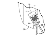
30・・・オイルレベルゲージ
F・・・車体フレーム
L2・・・直線
TL・・・接線
Claims (3)
- エンジン本体(14)と、該エンジン本体(14)の上方に配置される燃料タンク(15)と、該燃料タンク(15)の後方に配置される乗車用シート(16)とが車体フレーム(F)に支持され、前記車体フレーム(F)の幅方向一側で前記エンジン本体(14)の一側面を覆うエンジンカバー(25)に、前記エンジン本体(14)内の下部に貯留されるオイルのレベルを検出するためのオイルレベルゲージ(30)が配設される自動二輪車において、前記エンジン本体(14)に回転自在に支承される回転軸(26,27)の軸端に対応した位置で外方に膨らんだ膨出部(25a,25b)が、前後に分かれた2箇所で前記エンジンカバー(25)に形成され、前記オイルレベルゲージ(30)が、前記両膨出部(25a,25b)間の下部であって前記燃料タンク(15)の前後方向略中央部の下方に位置するようにして前記エンジンカバー(25)に配設されることを特徴とする自動二輪車におけるオイルレベル確認構造。
- 前記車体フレーム(F)が前端に備えるヘッドパイプ(11)よりも上方に配置されるトップブリッジ(12a)を有するフロントフォーク(12)が、前記ヘッドパイプ(11)で操向可能に支承され、側面視で前記トップブリッジ(12a)および前記オイルレベルゲージ(30)を結ぶ直線(L2)が前記両膨出部(25a,25b)間を通ることを特徴とする請求項1記載の自動二輪車におけるオイルレベル確認構造。
- 略円形に形成される一対の前記膨出部(25a,25b)の下部間を結ぶ接線(TL)よりも上方に前記オイルレベルゲージ(30)が配置されることを特徴とする請求項1または2記載の自動二輪車におけるオイルレベル確認構造。
Priority Applications (1)
| Application Number | Priority Date | Filing Date | Title |
|---|---|---|---|
| JP2007230673A JP4732409B2 (ja) | 2007-09-05 | 2007-09-05 | 自動二輪車におけるオイルレベル確認構造 |
Applications Claiming Priority (1)
| Application Number | Priority Date | Filing Date | Title |
|---|---|---|---|
| JP2007230673A JP4732409B2 (ja) | 2007-09-05 | 2007-09-05 | 自動二輪車におけるオイルレベル確認構造 |
Publications (2)
| Publication Number | Publication Date |
|---|---|
| JP2009062855A JP2009062855A (ja) | 2009-03-26 |
| JP4732409B2 true JP4732409B2 (ja) | 2011-07-27 |
Family
ID=40557664
Family Applications (1)
| Application Number | Title | Priority Date | Filing Date |
|---|---|---|---|
| JP2007230673A Expired - Fee Related JP4732409B2 (ja) | 2007-09-05 | 2007-09-05 | 自動二輪車におけるオイルレベル確認構造 |
Country Status (1)
| Country | Link |
|---|---|
| JP (1) | JP4732409B2 (ja) |
Families Citing this family (1)
| Publication number | Priority date | Publication date | Assignee | Title |
|---|---|---|---|---|
| JP5902983B2 (ja) * | 2012-03-30 | 2016-04-13 | 本田技研工業株式会社 | オイルレベルゲージ構造 |
Family Cites Families (5)
| Publication number | Priority date | Publication date | Assignee | Title |
|---|---|---|---|---|
| JPS5996414A (ja) * | 1982-11-24 | 1984-06-02 | Yamaha Motor Co Ltd | 自動二輪車等の車両におけるエンジンユニツト |
| JPS6287114A (ja) * | 1985-10-14 | 1987-04-21 | 松下電器産業株式会社 | 遠赤外線調理器 |
| JPH09228818A (ja) * | 1996-02-20 | 1997-09-02 | Suzuki Motor Corp | エンジンのオイルレベル表示器 |
| JP4605929B2 (ja) * | 2001-03-29 | 2011-01-05 | 本田技研工業株式会社 | 自動2輪車用内燃機関 |
| JP4003875B2 (ja) * | 2002-12-25 | 2007-11-07 | 本田技研工業株式会社 | 多気筒内燃機関 |
-
2007
- 2007-09-05 JP JP2007230673A patent/JP4732409B2/ja not_active Expired - Fee Related
Also Published As
| Publication number | Publication date |
|---|---|
| JP2009062855A (ja) | 2009-03-26 |
Similar Documents
| Publication | Publication Date | Title |
|---|---|---|
| JP5980250B2 (ja) | 鞍乗り型車両 | |
| EP3109147B1 (en) | Straddle type vehicle | |
| JP5025582B2 (ja) | 自動二輪車 | |
| EP2176115B1 (en) | Scooter type vehicle | |
| JP6088839B2 (ja) | 鞍乗型車両 | |
| JP5727911B2 (ja) | 鞍乗型車両の後部構造 | |
| JP2015085749A (ja) | 鞍乗型車両 | |
| JP5171149B2 (ja) | 自動二輪車における転倒センサの配設構造 | |
| CN103359225B (zh) | 骑乘式车辆 | |
| JP2010215214A (ja) | スクータ型車両 | |
| JP4567083B2 (ja) | 鞍乗型車両 | |
| JP5411241B2 (ja) | 鞍乗り型車両 | |
| JP4732409B2 (ja) | 自動二輪車におけるオイルレベル確認構造 | |
| JP6078370B2 (ja) | 鞍乗型車両 | |
| JP2020050218A (ja) | 鞍乗型車両 | |
| JP6448157B2 (ja) | 自動二輪車用ヘッドライトガード構造 | |
| JP2013230756A (ja) | 鞍乗型車両 | |
| JP5570940B2 (ja) | 鞍乗り型車両 | |
| JP2007112153A (ja) | 鞍乗り型車両 | |
| JP4875053B2 (ja) | 鞍乗り型車両 | |
| JP6861665B2 (ja) | 鞍乗り型車両 | |
| JP6846542B2 (ja) | 鞍乗り型車両 | |
| JP6664522B2 (ja) | 鞍乗り型車両 | |
| JP6682410B2 (ja) | 鞍乗型車両の冷却水リザーバタンク | |
| JP6923404B2 (ja) | 鞍乗り型車両 |
Legal Events
| Date | Code | Title | Description |
|---|---|---|---|
| A621 | Written request for application examination |
Free format text: JAPANESE INTERMEDIATE CODE: A621 Effective date: 20091126 |
|
| A977 | Report on retrieval |
Free format text: JAPANESE INTERMEDIATE CODE: A971007 Effective date: 20110325 |
|
| TRDD | Decision of grant or rejection written | ||
| A01 | Written decision to grant a patent or to grant a registration (utility model) |
Free format text: JAPANESE INTERMEDIATE CODE: A01 Effective date: 20110330 |
|
| A01 | Written decision to grant a patent or to grant a registration (utility model) |
Free format text: JAPANESE INTERMEDIATE CODE: A01 |
|
| A61 | First payment of annual fees (during grant procedure) |
Free format text: JAPANESE INTERMEDIATE CODE: A61 Effective date: 20110420 |
|
| FPAY | Renewal fee payment (event date is renewal date of database) |
Free format text: PAYMENT UNTIL: 20140428 Year of fee payment: 3 |
|
| R150 | Certificate of patent or registration of utility model |
Ref document number: 4732409 Country of ref document: JP Free format text: JAPANESE INTERMEDIATE CODE: R150 Free format text: JAPANESE INTERMEDIATE CODE: R150 |
|
| LAPS | Cancellation because of no payment of annual fees |