JP4802660B2 - 乗員拘束装置 - Google Patents
乗員拘束装置 Download PDFInfo
- Publication number
- JP4802660B2 JP4802660B2 JP2005314859A JP2005314859A JP4802660B2 JP 4802660 B2 JP4802660 B2 JP 4802660B2 JP 2005314859 A JP2005314859 A JP 2005314859A JP 2005314859 A JP2005314859 A JP 2005314859A JP 4802660 B2 JP4802660 B2 JP 4802660B2
- Authority
- JP
- Japan
- Prior art keywords
- bag
- end side
- seam
- pieces
- portions
- Prior art date
- Legal status (The legal status is an assumption and is not a legal conclusion. Google has not performed a legal analysis and makes no representation as to the accuracy of the status listed.)
- Expired - Fee Related
Links
- 238000003780 insertion Methods 0.000 claims description 21
- 230000037431 insertion Effects 0.000 claims description 21
- 230000002093 peripheral effect Effects 0.000 claims description 19
- 230000007423 decrease Effects 0.000 claims 1
- 230000000452 restraining effect Effects 0.000 description 4
- 230000008961 swelling Effects 0.000 description 2
- JOYRKODLDBILNP-UHFFFAOYSA-N Ethyl urethane Chemical compound CCOC(N)=O JOYRKODLDBILNP-UHFFFAOYSA-N 0.000 description 1
- 238000010586 diagram Methods 0.000 description 1
- 238000006073 displacement reaction Methods 0.000 description 1
- 238000000034 method Methods 0.000 description 1
- 230000000717 retained effect Effects 0.000 description 1
- 238000009958 sewing Methods 0.000 description 1
- 230000001629 suppression Effects 0.000 description 1
Images




Classifications
-
- B—PERFORMING OPERATIONS; TRANSPORTING
- B60—VEHICLES IN GENERAL
- B60N—SEATS SPECIALLY ADAPTED FOR VEHICLES; VEHICLE PASSENGER ACCOMMODATION NOT OTHERWISE PROVIDED FOR
- B60N2/00—Seats specially adapted for vehicles; Arrangement or mounting of seats in vehicles
- B60N2/24—Seats specially adapted for vehicles; Arrangement or mounting of seats in vehicles for particular purposes or particular vehicles
- B60N2/42—Seats specially adapted for vehicles; Arrangement or mounting of seats in vehicles for particular purposes or particular vehicles the seat constructed to protect the occupant from the effect of abnormal g-forces, e.g. crash or safety seats
- B60N2/427—Seats or parts thereof displaced during a crash
- B60N2/42727—Seats or parts thereof displaced during a crash involving substantially rigid displacement
- B60N2/42754—Seats or parts thereof displaced during a crash involving substantially rigid displacement of the cushion
- B60N2/42763—Seats or parts thereof displaced during a crash involving substantially rigid displacement of the cushion with anti-submarining systems
-
- B—PERFORMING OPERATIONS; TRANSPORTING
- B60—VEHICLES IN GENERAL
- B60R—VEHICLES, VEHICLE FITTINGS, OR VEHICLE PARTS, NOT OTHERWISE PROVIDED FOR
- B60R21/00—Arrangements or fittings on vehicles for protecting or preventing injuries to occupants or pedestrians in case of accidents or other traffic risks
- B60R21/02—Occupant safety arrangements or fittings, e.g. crash pads
- B60R21/16—Inflatable occupant restraints or confinements designed to inflate upon impact or impending impact, e.g. air bags
- B60R21/20—Arrangements for storing inflatable members in their non-use or deflated condition; Arrangement or mounting of air bag modules or components
- B60R21/207—Arrangements for storing inflatable members in their non-use or deflated condition; Arrangement or mounting of air bag modules or components in vehicle seats
-
- B—PERFORMING OPERATIONS; TRANSPORTING
- B60—VEHICLES IN GENERAL
- B60R—VEHICLES, VEHICLE FITTINGS, OR VEHICLE PARTS, NOT OTHERWISE PROVIDED FOR
- B60R21/00—Arrangements or fittings on vehicles for protecting or preventing injuries to occupants or pedestrians in case of accidents or other traffic risks
- B60R21/02—Occupant safety arrangements or fittings, e.g. crash pads
- B60R21/16—Inflatable occupant restraints or confinements designed to inflate upon impact or impending impact, e.g. air bags
- B60R21/23—Inflatable members
- B60R21/235—Inflatable members characterised by their material
- B60R2021/23571—Inflatable members characterised by their material characterised by connections between panels
- B60R2021/23576—Sewing
Landscapes
- Engineering & Computer Science (AREA)
- Mechanical Engineering (AREA)
- Aviation & Aerospace Engineering (AREA)
- Transportation (AREA)
- Air Bags (AREA)
- Seats For Vehicles (AREA)
Description
請求項4の乗員拘束装置は、請求項1ないし3のいずれか1項において、前記バッグ(12)は、非膨張時には、前記シートパン(8)の上面に沿って平たく、且つシート前後方向の幅が小さくなるように折り畳まれた状態にて該シートパン(8)に取り付けられており、該バッグ(12)の折り畳みに際し、該バッグ(12)は、前記平延状態とされた後、その前後方向の中間付近よりも前半側及び後半側がそれぞれ該前後方向の途中から左右方向折り返し線(F 1 ,F 2 )に沿って該前後方向中央側へ折り返されていることを特徴とするものである。
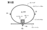
1a,1b サイドフレーム
4 バックフレーム
6 ヘッドレスト
8 シートパン
10 乗員拘束装置
12,12A バッグ
12a 固定部
12b ボルト挿通孔
13 インフレータ
14 ボルト
15 空室
20〜22 シーム
L1 固定部12a,12a同士(ボルト挿通孔12b,12b同士)の間の距離
L2 空室15の左右方向の最大長さ
L3 空室15の前後方向の最大幅
Claims (4)
- シートの左右幅方向に延在するようにシートクッションとシートパン(8)との間に配置され、該シートクッションの前部を下側から押圧するように膨張可能なバッグ(12)と、
車両緊急時に該バッグ(12)を膨張させるガス発生器(13)と、
を有し、該バッグ(12)は該シートパン(8)の左右方向に延在しており、
該バッグ(12)の左右両端側の固定部(12a,12a)がそれぞれシートパン(8)にボルト(14)で連結されている乗員拘束装置において、
該バッグ(12)は、該固定部(12a,12a)同士の間に、ガスが導入されて膨張する空室(15)が形成されたものであり、
該バッグ(12)の左端側の固定部(12a)が該シートパン(8)の左端部に連結され、該バッグ(12)の右端側の固定部(12a)が該シートパン(8)の右端部に連結されており、
該バッグ(12)は、該バッグ(12)の膨張時の外周面の上半側及び下半側をそれぞれ構成するアッパーパネル(16)とロワパネル(17)とを重ね合わせ、これらを第1のシーム(20)により縫合して袋状としたものであり、
該アッパーパネル(16)及びロワパネル(17)は、それぞれ、1対の対向辺が左右方向に延在した横長の主片部と、該主片部の左右方向の両端側からそれぞれ側方へ張り出した1対の張出片部とを有しており、各張出片部の張り出し方向の先端側に、前記ボルト(14)が挿通されたボルト挿通孔(12b)が設けられており、
該アッパーパネル(16)とロワパネル(17)との左端側の張出片部同士及び右端側の張出片部同士がそれぞれ重ね合わされ、重なり合った該張出片部同士の該ボルト挿通孔(12b)の周縁部同士がそれぞれ第2のシーム(21)によって縫合されており、
該第2のシーム(21)によって縫合された該アッパーパネル(16)とロワパネル(17)との左端側の張出片部同士及び右端側の張出片部同士によってそれぞれ該バッグ(12)の左端側の固定部(12a)及び右端側の固定部(12a)が構成されており、
該アッパーパネル(16)とロワパネル(17)との該主片部同士が重ね合わされ、重なり合った該主片部の周縁部同士が前記第1のシーム(20)によって縫合されることにより、該主片部同士の間に前記空室(15)が形成されており、
該第1のシーム(20)は、該主片部の前記1対の対向辺に沿ってそれぞれ左右方向に延在した1対の左右方向延在部と、両固定部(12a,12a)における前記第2のシーム(21,21)よりも該主片部の左右方向の中央側において両左右方向延在部の一端側同士及び他端側同士をそれぞれ繋いでおり、該アッパーパネル(16)及びロワパネル(17)の左右方向両端側に向って凸となるように略円弧状に延在した1対の略円弧状部とを有しており、
非膨張状態の該バッグ(12)を平たく展延した平延状態における該固定部(12a,12a)のボルト挿通孔(12b,12b)の中心同士の距離をL1、空室(15)の前記左右方向の最大長さをL2 、該平延状態における該空室(15)の前後方向の最大幅をL 3 とした場合、
L2/L1が0.6〜0.9であり、
L 3 /L 2 が0.4〜0.85であり、
L 1 /L 3 が2.1以下であり、
前記ガス発生器(13)は該バッグ(12)の内側に設置されていることを特徴とする乗員拘束装置。 - シートの左右幅方向に延在するようにシートクッションとシートパン(8)との間に配置され、該シートクッションの前部を下側から押圧するように膨張可能なバッグ(12)と、
車両緊急時に該バッグ(12)を膨張させるガス発生器(13)と、
を有し、該バッグ(12)は該シートパン(8)の左右方向に延在しており、
該バッグ(12)の左右両端側の固定部(12a,12a)がそれぞれシートパン(8)にボルト(14)で連結されている乗員拘束装置において、
該バッグ(12)は、該固定部(12a,12a)同士の間に、ガスが導入されて膨張する空室(15)が形成されたものであり、
該バッグ(12)の左端側の固定部(12a)が該シートパン(8)の左端部に連結され、該バッグ(12)の右端側の固定部(12a)が該シートパン(8)の右端部に連結されており、
該バッグ(12)は、該バッグ(12)の膨張時の外周面の上半側及び下半側をそれぞれ構成するアッパーパネル(16)とロワパネル(17)とを重ね合わせ、これらを第1のシーム(20)により縫合して袋状としたものであり、
該アッパーパネル(16)及びロワパネル(17)は、それぞれ、1対の対向辺が左右方向に延在した横長の主片部と、該主片部の左右方向の両端側からそれぞれ側方へ張り出した1対の張出片部とを有しており、各張出片部の張り出し方向の先端側に、前記ボルト(14)が挿通されたボルト挿通孔(12b)が設けられており、
該アッパーパネル(16)とロワパネル(17)との左端側の張出片部同士及び右端側の張出片部同士がそれぞれ重ね合わされ、重なり合った該張出片部同士の該ボルト挿通孔(12b)の周縁部同士がそれぞれ第2のシーム(21)によって縫合されており、
該第2のシーム(21)によって縫合された該アッパーパネル(16)とロワパネル(17)との左端側の張出片部同士及び右端側の張出片部同士によってそれぞれ該バッグ(12)の左端側の固定部(12a)及び右端側の固定部(12a)が構成されており、
該アッパーパネル(16)とロワパネル(17)との該主片部同士が重ね合わされ、重なり合った該主片部の周縁部同士が前記第1のシーム(20)によって縫合されることにより、該主片部同士の間に前記空室(15)が形成されており、
該第1のシーム(20)は、該主片部の前記1対の対向辺に沿ってそれぞれ左右方向に延在した1対の左右方向延在部と、両固定部(12a,12a)における前記第2のシーム(21,21)よりも該主片部の左右方向の中央側において両左右方向延在部の一端側同士及び他端側同士をそれぞれ繋いでおり、該アッパーパネル(16)及びロワパネル(17)の左右方向両端側に向って凸となるように略円弧状に延在した1対の略円弧状部とを有しており、
非膨張状態の該バッグ(12)を平たく展延した平延状態における該固定部(12a,12a)のボルト挿通孔(12b,12b)の中心同士の距離をL 1 、空室(15)の前記左右方向の最大長さをL 2 、該平延状態における該空室(15)の前後方向の最大幅をL 3 とした場合、
L 2 /L 1 が0.6〜0.9であり、
L 3 /L 2 が0.4〜0.85であり、
L 1 /L 3 が2.1以下であり、
前記ガス発生器(13)は該バッグ(12)の外部に設置されており、
該バッグ(12)は、その左右方向の一端側に、該空室(15)に連通したダクト部(30)が設けられており、
該ダクト部(30)に、該ガス発生器(13)からのガス供給部材が結合されており、
該ダクト部(30)及びガス供給部材を介して該ガス発生器(13)から該空室(15)内にガスが導入されるように構成されていることを特徴とする乗員拘束装置。 - 請求項1又は2において、前記アッパーパネル(16)及びロワパネル(17)の各張出片部は、それぞれ、前記主片部からの張り出し方向の基端側においては、その前後方向の幅が該主片部の左右両端側の前後方向の幅と同等であり、該張り出し方向の先端側ほどその前後方向の幅が小さくなる略三角形状のものであり、
前記固定部(12a,12a)において、それぞれ、重なり合った該アッパーパネル(16)とロワパネル(17)との張出片部の周縁部同士が該三角形の斜辺に沿って第3のシーム(22)によって縫合されており、
各固定部(12a)において、該第3のシーム(22)の両端側は前記第1のシーム(20)に合流しており、該第3のシーム(22)の延在方向の中間付近は前記第2のシーム(21)に合流していることを特徴とする乗員拘束装置。 - 請求項1ないし3のいずれか1項において、前記バッグ(12)は、非膨張時には、前記シートパン(8)の上面に沿って平たく、且つシート前後方向の幅が小さくなるように折り畳まれた状態にて該シートパン(8)に取り付けられており、
該バッグ(12)の折り畳みに際し、該バッグ(12)は、前記平延状態とされた後、その前後方向の中間付近よりも前半側及び後半側がそれぞれ該前後方向の途中から左右方向折り返し線(F 1 ,F 2 )に沿って該前後方向中央側へ折り返されていることを特徴とする乗員拘束装置。
Priority Applications (5)
| Application Number | Priority Date | Filing Date | Title |
|---|---|---|---|
| JP2005314859A JP4802660B2 (ja) | 2005-10-28 | 2005-10-28 | 乗員拘束装置 |
| EP06822048A EP1939050A1 (en) | 2005-10-28 | 2006-10-23 | Occupant restraint device |
| US12/091,021 US7823915B2 (en) | 2005-10-28 | 2006-10-23 | Occupant restraining device |
| CNA200680021343XA CN101198493A (zh) | 2005-10-28 | 2006-10-23 | 乘员约束装置 |
| PCT/JP2006/321028 WO2007049540A1 (ja) | 2005-10-28 | 2006-10-23 | 乗員拘束装置 |
Applications Claiming Priority (1)
| Application Number | Priority Date | Filing Date | Title |
|---|---|---|---|
| JP2005314859A JP4802660B2 (ja) | 2005-10-28 | 2005-10-28 | 乗員拘束装置 |
Publications (2)
| Publication Number | Publication Date |
|---|---|
| JP2007118819A JP2007118819A (ja) | 2007-05-17 |
| JP4802660B2 true JP4802660B2 (ja) | 2011-10-26 |
Family
ID=37967652
Family Applications (1)
| Application Number | Title | Priority Date | Filing Date |
|---|---|---|---|
| JP2005314859A Expired - Fee Related JP4802660B2 (ja) | 2005-10-28 | 2005-10-28 | 乗員拘束装置 |
Country Status (5)
| Country | Link |
|---|---|
| US (1) | US7823915B2 (ja) |
| EP (1) | EP1939050A1 (ja) |
| JP (1) | JP4802660B2 (ja) |
| CN (1) | CN101198493A (ja) |
| WO (1) | WO2007049540A1 (ja) |
Families Citing this family (1)
| Publication number | Priority date | Publication date | Assignee | Title |
|---|---|---|---|---|
| US9616839B2 (en) * | 2014-05-18 | 2017-04-11 | Toyota Motor Engineering & Manufacturing North America, Inc. | H-point referenced seat cushion airbag system |
Family Cites Families (13)
| Publication number | Priority date | Publication date | Assignee | Title |
|---|---|---|---|---|
| JPS525126A (en) | 1975-07-01 | 1977-01-14 | Arakawa Shatai Kogyo Kk | Air bag for vehicle |
| DE69532094T2 (de) * | 1994-09-08 | 2004-08-26 | Breed Automotive Technology, Inc., Lakeland | Luftsack zum Schützen von Kraftfahrzeuginsassen |
| JP3652450B2 (ja) | 1996-07-17 | 2005-05-25 | 芦森工業株式会社 | 助手席用エアバッグ |
| JP3285129B2 (ja) | 1997-01-31 | 2002-05-27 | ジョンソン コントロールズ オートモーティブ システムズ株式会社 | 車両用シート |
| JP4314766B2 (ja) * | 1998-06-01 | 2009-08-19 | タカタ株式会社 | エアバッグ |
| JP4269826B2 (ja) * | 2003-03-12 | 2009-05-27 | タカタ株式会社 | 乗員保護装置 |
| JP4063168B2 (ja) * | 2003-07-11 | 2008-03-19 | 豊田合成株式会社 | 膝保護用エアバッグ |
| JP4238675B2 (ja) * | 2003-08-26 | 2009-03-18 | タカタ株式会社 | 乗員保護装置 |
| US20060017266A1 (en) * | 2003-09-30 | 2006-01-26 | Takata Corporation | Passenger protecting device |
| JP2005231505A (ja) | 2004-02-19 | 2005-09-02 | Takata Corp | 乗員保護装置 |
| JP2005280442A (ja) | 2004-03-29 | 2005-10-13 | Takata Corp | 乗員保護装置及びその設置構造 |
| JP4715523B2 (ja) * | 2005-10-25 | 2011-07-06 | タカタ株式会社 | 乗員拘束装置 |
| JP2007118817A (ja) * | 2005-10-28 | 2007-05-17 | Takata Corp | 乗員拘束装置 |
-
2005
- 2005-10-28 JP JP2005314859A patent/JP4802660B2/ja not_active Expired - Fee Related
-
2006
- 2006-10-23 CN CNA200680021343XA patent/CN101198493A/zh active Pending
- 2006-10-23 WO PCT/JP2006/321028 patent/WO2007049540A1/ja not_active Ceased
- 2006-10-23 EP EP06822048A patent/EP1939050A1/en active Pending
- 2006-10-23 US US12/091,021 patent/US7823915B2/en not_active Expired - Fee Related
Also Published As
| Publication number | Publication date |
|---|---|
| US7823915B2 (en) | 2010-11-02 |
| CN101198493A (zh) | 2008-06-11 |
| JP2007118819A (ja) | 2007-05-17 |
| US20090127832A1 (en) | 2009-05-21 |
| EP1939050A1 (en) | 2008-07-02 |
| WO2007049540A1 (ja) | 2007-05-03 |
Similar Documents
| Publication | Publication Date | Title |
|---|---|---|
| JP5724909B2 (ja) | サイドエアバッグ装置 | |
| JP6380340B2 (ja) | 乗員保護装置 | |
| JP6919383B2 (ja) | サイドエアバッグ装置を搭載した車両用シート | |
| JP7098548B2 (ja) | エアバッグシステム | |
| CN107531206A (zh) | 乘员保护装置 | |
| JP2006035988A (ja) | サイドエアバッグ装置 | |
| JP2009137441A (ja) | 乗員拘束装置 | |
| CN112141038B (zh) | 侧面安全气囊装置和膝部安全气囊装置 | |
| US20070080522A1 (en) | Airbag and airbag system | |
| JP2007118817A (ja) | 乗員拘束装置 | |
| JP4997754B2 (ja) | 乗員拘束装置 | |
| JP4802659B2 (ja) | 乗員拘束装置 | |
| JP6036450B2 (ja) | ファーサイド乗員拘束装置及び車両用シート | |
| JP6544263B2 (ja) | サイドエアバッグ装置 | |
| JP2007099169A (ja) | エアバッグ装置 | |
| JP4802660B2 (ja) | 乗員拘束装置 | |
| JP2007161203A (ja) | 乗員拘束装置 | |
| JP2009190530A (ja) | サイドエアバッグ装置 | |
| JP7533236B2 (ja) | 車両用サイドエアバッグ装置 | |
| JP4122195B2 (ja) | エアバッグ装置 | |
| JP4747824B2 (ja) | 乗員拘束装置 | |
| JP5724908B2 (ja) | サイドエアバッグ装置 | |
| JP7722945B2 (ja) | エアバッグ装置 | |
| JP5915479B2 (ja) | サイドエアバッグ装置 | |
| JP2026008036A (ja) | 車両用カーテンエアバッグ装置 |
Legal Events
| Date | Code | Title | Description |
|---|---|---|---|
| A621 | Written request for application examination |
Free format text: JAPANESE INTERMEDIATE CODE: A621 Effective date: 20080912 |
|
| A131 | Notification of reasons for refusal |
Free format text: JAPANESE INTERMEDIATE CODE: A131 Effective date: 20110412 |
|
| A521 | Request for written amendment filed |
Free format text: JAPANESE INTERMEDIATE CODE: A523 Effective date: 20110606 |
|
| TRDD | Decision of grant or rejection written | ||
| A01 | Written decision to grant a patent or to grant a registration (utility model) |
Free format text: JAPANESE INTERMEDIATE CODE: A01 Effective date: 20110712 |
|
| A01 | Written decision to grant a patent or to grant a registration (utility model) |
Free format text: JAPANESE INTERMEDIATE CODE: A01 |
|
| A61 | First payment of annual fees (during grant procedure) |
Free format text: JAPANESE INTERMEDIATE CODE: A61 Effective date: 20110725 |
|
| R150 | Certificate of patent or registration of utility model |
Free format text: JAPANESE INTERMEDIATE CODE: R150 Ref document number: 4802660 Country of ref document: JP Free format text: JAPANESE INTERMEDIATE CODE: R150 |
|
| FPAY | Renewal fee payment (event date is renewal date of database) |
Free format text: PAYMENT UNTIL: 20140819 Year of fee payment: 3 |
|
| R250 | Receipt of annual fees |
Free format text: JAPANESE INTERMEDIATE CODE: R250 |
|
| R250 | Receipt of annual fees |
Free format text: JAPANESE INTERMEDIATE CODE: R250 |
|
| R250 | Receipt of annual fees |
Free format text: JAPANESE INTERMEDIATE CODE: R250 |
|
| R250 | Receipt of annual fees |
Free format text: JAPANESE INTERMEDIATE CODE: R250 |
|
| S111 | Request for change of ownership or part of ownership |
Free format text: JAPANESE INTERMEDIATE CODE: R313113 |
|
| S343 | Written request for registration of root pledge or change of root pledge |
Free format text: JAPANESE INTERMEDIATE CODE: R316354 |
|
| SZ02 | Written request for trust registration |
Free format text: JAPANESE INTERMEDIATE CODE: R316Z02 |
|
| S343 | Written request for registration of root pledge or change of root pledge |
Free format text: JAPANESE INTERMEDIATE CODE: R316354 |
|
| R350 | Written notification of registration of transfer |
Free format text: JAPANESE INTERMEDIATE CODE: R350 |
|
| S343 | Written request for registration of root pledge or change of root pledge |
Free format text: JAPANESE INTERMEDIATE CODE: R316354 |
|
| SZ02 | Written request for trust registration |
Free format text: JAPANESE INTERMEDIATE CODE: R316Z02 |
|
| R350 | Written notification of registration of transfer |
Free format text: JAPANESE INTERMEDIATE CODE: R350 |
|
| R250 | Receipt of annual fees |
Free format text: JAPANESE INTERMEDIATE CODE: R250 |
|
| LAPS | Cancellation because of no payment of annual fees |