JP4875141B2 - ストローク伝達装置 - Google Patents
ストローク伝達装置 Download PDFInfo
- Publication number
- JP4875141B2 JP4875141B2 JP2009501911A JP2009501911A JP4875141B2 JP 4875141 B2 JP4875141 B2 JP 4875141B2 JP 2009501911 A JP2009501911 A JP 2009501911A JP 2009501911 A JP2009501911 A JP 2009501911A JP 4875141 B2 JP4875141 B2 JP 4875141B2
- Authority
- JP
- Japan
- Prior art keywords
- adjusting means
- stroke
- transmission device
- cam
- control cam
- Prior art date
- Legal status (The legal status is an assumption and is not a legal conclusion. Google has not performed a legal analysis and makes no representation as to the accuracy of the status listed.)
- Expired - Fee Related
Links
- 230000005540 biological transmission Effects 0.000 title claims description 23
- 230000033001 locomotion Effects 0.000 claims description 34
- 238000006073 displacement reaction Methods 0.000 claims 1
- KJFBVJALEQWJBS-XUXIUFHCSA-N maribavir Chemical compound CC(C)NC1=NC2=CC(Cl)=C(Cl)C=C2N1[C@H]1O[C@@H](CO)[C@H](O)[C@@H]1O KJFBVJALEQWJBS-XUXIUFHCSA-N 0.000 claims 1
- 238000000034 method Methods 0.000 description 7
- 238000002485 combustion reaction Methods 0.000 description 5
- 238000004519 manufacturing process Methods 0.000 description 3
- 238000006243 chemical reaction Methods 0.000 description 2
- 230000006835 compression Effects 0.000 description 2
- 238000007906 compression Methods 0.000 description 2
- 230000003247 decreasing effect Effects 0.000 description 1
- 230000003111 delayed effect Effects 0.000 description 1
- 230000001419 dependent effect Effects 0.000 description 1
- 238000010586 diagram Methods 0.000 description 1
- 230000000694 effects Effects 0.000 description 1
- 238000009434 installation Methods 0.000 description 1
Images

Classifications
-
- F—MECHANICAL ENGINEERING; LIGHTING; HEATING; WEAPONS; BLASTING
- F01—MACHINES OR ENGINES IN GENERAL; ENGINE PLANTS IN GENERAL; STEAM ENGINES
- F01L—CYCLICALLY OPERATING VALVES FOR MACHINES OR ENGINES
- F01L13/00—Modifications of valve-gear to facilitate reversing, braking, starting, changing compression ratio, or other specific operations
- F01L13/0015—Modifications of valve-gear to facilitate reversing, braking, starting, changing compression ratio, or other specific operations for optimising engine performances by modifying valve lift according to various working parameters, e.g. rotational speed, load, torque
- F01L13/0021—Modifications of valve-gear to facilitate reversing, braking, starting, changing compression ratio, or other specific operations for optimising engine performances by modifying valve lift according to various working parameters, e.g. rotational speed, load, torque by modification of rocker arm ratio
-
- F—MECHANICAL ENGINEERING; LIGHTING; HEATING; WEAPONS; BLASTING
- F01—MACHINES OR ENGINES IN GENERAL; ENGINE PLANTS IN GENERAL; STEAM ENGINES
- F01L—CYCLICALLY OPERATING VALVES FOR MACHINES OR ENGINES
- F01L13/00—Modifications of valve-gear to facilitate reversing, braking, starting, changing compression ratio, or other specific operations
- F01L13/0015—Modifications of valve-gear to facilitate reversing, braking, starting, changing compression ratio, or other specific operations for optimising engine performances by modifying valve lift according to various working parameters, e.g. rotational speed, load, torque
- F01L13/0021—Modifications of valve-gear to facilitate reversing, braking, starting, changing compression ratio, or other specific operations for optimising engine performances by modifying valve lift according to various working parameters, e.g. rotational speed, load, torque by modification of rocker arm ratio
- F01L13/0026—Modifications of valve-gear to facilitate reversing, braking, starting, changing compression ratio, or other specific operations for optimising engine performances by modifying valve lift according to various working parameters, e.g. rotational speed, load, torque by modification of rocker arm ratio by means of an eccentric
-
- F—MECHANICAL ENGINEERING; LIGHTING; HEATING; WEAPONS; BLASTING
- F01—MACHINES OR ENGINES IN GENERAL; ENGINE PLANTS IN GENERAL; STEAM ENGINES
- F01L—CYCLICALLY OPERATING VALVES FOR MACHINES OR ENGINES
- F01L13/00—Modifications of valve-gear to facilitate reversing, braking, starting, changing compression ratio, or other specific operations
- F01L13/0015—Modifications of valve-gear to facilitate reversing, braking, starting, changing compression ratio, or other specific operations for optimising engine performances by modifying valve lift according to various working parameters, e.g. rotational speed, load, torque
- F01L13/0063—Modifications of valve-gear to facilitate reversing, braking, starting, changing compression ratio, or other specific operations for optimising engine performances by modifying valve lift according to various working parameters, e.g. rotational speed, load, torque by modification of cam contact point by displacing an intermediate lever or wedge-shaped intermediate element, e.g. Tourtelot
-
- F—MECHANICAL ENGINEERING; LIGHTING; HEATING; WEAPONS; BLASTING
- F01—MACHINES OR ENGINES IN GENERAL; ENGINE PLANTS IN GENERAL; STEAM ENGINES
- F01L—CYCLICALLY OPERATING VALVES FOR MACHINES OR ENGINES
- F01L13/00—Modifications of valve-gear to facilitate reversing, braking, starting, changing compression ratio, or other specific operations
- F01L13/0015—Modifications of valve-gear to facilitate reversing, braking, starting, changing compression ratio, or other specific operations for optimising engine performances by modifying valve lift according to various working parameters, e.g. rotational speed, load, torque
- F01L13/0063—Modifications of valve-gear to facilitate reversing, braking, starting, changing compression ratio, or other specific operations for optimising engine performances by modifying valve lift according to various working parameters, e.g. rotational speed, load, torque by modification of cam contact point by displacing an intermediate lever or wedge-shaped intermediate element, e.g. Tourtelot
- F01L2013/0068—Modifications of valve-gear to facilitate reversing, braking, starting, changing compression ratio, or other specific operations for optimising engine performances by modifying valve lift according to various working parameters, e.g. rotational speed, load, torque by modification of cam contact point by displacing an intermediate lever or wedge-shaped intermediate element, e.g. Tourtelot with an oscillating cam acting on the valve of the "BMW-Valvetronic" type
Landscapes
- Engineering & Computer Science (AREA)
- Mechanical Engineering (AREA)
- General Engineering & Computer Science (AREA)
- Valve Device For Special Equipments (AREA)
- Gears, Cams (AREA)
- Transmission Devices (AREA)
Description
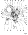
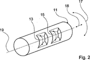
11 調節手段
12 調節手段
13 制御カム
14 制御カム
15 制御カム
16 制御カム
17 自由度
18 自由度
19 軸
20 アクチュエータ
21 中間レバー
22 軸受領域
23 軸受領域
24 カムシャフト
25 カム
26 端部
27 案内カム
28 円形経路
29 本体部
30 入力従動部材
31 湾曲部
32 経路
33 凹部
34 従動部材
35 案内シュー
36 支持外形
37 支持手段
38 ストロークカム
39 ゼロストロークカム
40 ローラレバー
41 隙間補償要素
42 矢印
43 矢印
44 矢印
45 螺旋状の圧縮バネ
46 接触領域
Claims (10)
- カムを持つカムシャフトと、カムシャフトのカムと協働し、カムシャフトの回転を被作動部材のストローク動作に変換する調節ユニットとを備え、前記調節ユニットは前記被作動部材のストローク動作を調節することができ、
前記調節ユニットは第1の調節手段(11)及び少なくとも1つの第2の調節手段(12)を有し、
前記第1の調節手段(11)は、少なくとも1つの第1の制御カムを有し、前記少なくとも1つの第1の制御カムを介して前記第2の調節手段(12)は前記第1の調節手段(11)と連結されることができ、
前記第2の調節手段(12)は、前記第1の調節手段(11)との第1の相対運動(17)により前記制御カムの接触領域において変位することにより、前記被作動部材に一定のストロークをさせることができ、
前記第2の調節手段(12)は、前記第1の調節手段(11)との前記第1の相対運動(17)とは異なる第2の相対運動(18)により前記制御カムの接触領域において変位することにより、前記被作動部材のストロークを調節することができるストローク伝達装置であって、
前記第1の調節手段(11)は、前記第1の制御カム(15)とは異なる接触領域を有する他の第2の制御カム(16)を有し、前記第2の調節手段(12)は、前記第1の調節手段(11)の第1の相対運動(17)により、前記第1の制御カム(15)と前記第2の制御カム(16)との間を変位することができることを特徴とするストローク伝達装置。 - 前記第1の相対運動(17)及び第2の相対運動(18)が互いに対して少なくともほぼ垂直に定められることを特徴とする請求項1に記載のストローク伝達装置。
- 少なくとも1つの前記調節手段(11)が、並進移動することができることを特徴とする請求項1又は2に記載のストローク伝達装置。
- 並進移動することができる前記調節手段(11)は、少なくとも1つの軸(19)を中心に回転可能であることを特徴とする請求項3に記載のストローク伝達装置。
- 前記制御カムが、少なくとも1つの外形領域で少なくとも1つの方向に一定の半径を有することを特徴とする請求項1〜4のいずれか1項に記載のストローク伝達装置。
- 前記調節ユニットが、前記調節手段(11)の一方の端部領域に取付けられた少なくとも1つのアクチュエータ(20)を有することを特徴とする請求項1〜5のいずれか1項に記載のストローク伝達装置。
- 前記調節ユニットの前記第1の調節手段(11)が、少なくとも2つの被作動部材用の少なくとも2つの制御カム(13、14、15、16)を有することを特徴とする請求項1〜6のいずれか1項に記載のストローク伝達装置。
- 前記少なくとも2つの被作動部材のストローク動作間の差を発生させるため、前記第1及び第2の調節手段(11、12)が、少なくとも1つの相対運動で互いに対して変位することができることを特徴とする請求項7に記載のストローク伝達装置。
- 前記調節ユニットが、前記カムシャフトの回転を旋回運動に変換するための中間レバー(21)を有することを特徴とする請求項1〜8のいずれか1項に記載のストローク伝達装置。
- 前記中間レバー(21)が、少なくとも1つの調節手段(11、12)用の少なくとも1つの軸受領域(22、23)を有することを特徴とする請求項9に記載のストローク伝達装置。
Applications Claiming Priority (3)
| Application Number | Priority Date | Filing Date | Title |
|---|---|---|---|
| DE102006013915.1 | 2006-03-25 | ||
| DE102006013915A DE102006013915A1 (de) | 2006-03-25 | 2006-03-25 | Hubübertragungsvorrichtung |
| PCT/EP2007/002456 WO2007110174A1 (de) | 2006-03-25 | 2007-03-20 | Hubübertragungsvorrichtung |
Publications (2)
| Publication Number | Publication Date |
|---|---|
| JP2009531586A JP2009531586A (ja) | 2009-09-03 |
| JP4875141B2 true JP4875141B2 (ja) | 2012-02-15 |
Family
ID=38353748
Family Applications (1)
| Application Number | Title | Priority Date | Filing Date |
|---|---|---|---|
| JP2009501911A Expired - Fee Related JP4875141B2 (ja) | 2006-03-25 | 2007-03-20 | ストローク伝達装置 |
Country Status (4)
| Country | Link |
|---|---|
| US (1) | US8136491B2 (ja) |
| JP (1) | JP4875141B2 (ja) |
| DE (1) | DE102006013915A1 (ja) |
| WO (1) | WO2007110174A1 (ja) |
Citations (1)
| Publication number | Priority date | Publication date | Assignee | Title |
|---|---|---|---|---|
| JPS5887904A (ja) * | 1981-11-19 | 1983-05-25 | Sanyo Electric Co Ltd | 増幅器 |
Family Cites Families (15)
| Publication number | Priority date | Publication date | Assignee | Title |
|---|---|---|---|---|
| US5056476A (en) * | 1990-08-28 | 1991-10-15 | King Brian T | Variable valve duration and lift for an internal combustion engine |
| DE19913742A1 (de) * | 1999-03-26 | 2000-09-28 | Bayerische Motoren Werke Ag | Vorrichtung zur Hubverstellung eines Gaswechselventils im Zylinderkopf einer Brennkraftmaschine |
| ATE220444T1 (de) * | 1999-10-29 | 2002-07-15 | Sts System Technology Services | Mechanische regelung der hubverstellung des einlassventils eines verbrennungsmotors |
| DE10061618B4 (de) * | 2000-12-11 | 2004-06-03 | Iav Gmbh Ingenieurgesellschaft Auto Und Verkehr | Einrichtung zur variablen Betätigung von Ventilen mittels Nocken für Verbrennungsmotoren |
| DE10119686B4 (de) * | 2001-04-20 | 2006-03-30 | Iav Gmbh Ingenieurgesellschaft Auto Und Verkehr | Variabler Ventiltrieb |
| DE10123186A1 (de) * | 2001-05-12 | 2002-11-14 | Bayerische Motoren Werke Ag | Ventiltrieb-Vorrichtung zur variablen Hubverstellung eines Gaswechselventils einer Brennkraftmaschine |
| DE10140635B4 (de) * | 2001-08-13 | 2010-12-02 | Entec Consulting Gmbh | Vorrichtung zur variablen Ventilhubverstellung von Gaswechselventilen einer Verbrennungskraftmaschine |
| DE10306907B4 (de) * | 2003-02-17 | 2004-12-09 | Iav Gmbh Ingenieurgesellschaft Auto Und Verkehr | Ventiltrieb mit variabel einstellbarem Hub für Ventile von Verbrennungsmotoren |
| DE10314683B4 (de) * | 2003-03-29 | 2009-05-07 | Entec Consulting Gmbh | Variable Ventilhubsteuerung für einen Verbrennungsmotor mit untenliegender Nockenwelle |
| DE10341702A1 (de) * | 2003-09-10 | 2005-04-28 | Bayerische Motoren Werke Ag | Ventiltrieb für eine Hubkolben-Brennkraftmaschine |
| DE102004035005A1 (de) * | 2004-07-20 | 2006-02-16 | Bayerische Motoren Werke Ag | Ventiltrieb einer Brennkraftmaschine |
| CA2555638C (en) * | 2005-08-15 | 2009-09-15 | Honda Motor Co., Ltd. | Lift-variable valve-operating system for internal combustion engine |
| KR100667394B1 (ko) * | 2005-11-15 | 2007-01-10 | 현대자동차주식회사 | 엔진의 연속 가변 밸브 리프트 장치 |
| DE602007004775D1 (de) * | 2006-06-27 | 2010-04-01 | Otics Corp | Variabler Ventilmechanismus |
| US7823552B2 (en) * | 2007-08-01 | 2010-11-02 | Hyundai Motor Company | Continuous variable valve lift apparatus |
-
2006
- 2006-03-25 DE DE102006013915A patent/DE102006013915A1/de not_active Withdrawn
-
2007
- 2007-03-20 JP JP2009501911A patent/JP4875141B2/ja not_active Expired - Fee Related
- 2007-03-20 WO PCT/EP2007/002456 patent/WO2007110174A1/de not_active Ceased
-
2008
- 2008-09-24 US US12/284,626 patent/US8136491B2/en not_active Expired - Fee Related
Patent Citations (1)
| Publication number | Priority date | Publication date | Assignee | Title |
|---|---|---|---|---|
| JPS5887904A (ja) * | 1981-11-19 | 1983-05-25 | Sanyo Electric Co Ltd | 増幅器 |
Also Published As
| Publication number | Publication date |
|---|---|
| US20090095242A1 (en) | 2009-04-16 |
| JP2009531586A (ja) | 2009-09-03 |
| DE102006013915A1 (de) | 2007-09-27 |
| WO2007110174A1 (de) | 2007-10-04 |
| US8136491B2 (en) | 2012-03-20 |
Similar Documents
| Publication | Publication Date | Title |
|---|---|---|
| JP5582195B2 (ja) | 可変動弁装置 | |
| US7603973B2 (en) | Variable mechanical valve control for an internal combustion engine | |
| KR101584818B1 (ko) | 피니언의 선회 운동을 슬라이드의 병진 운동으로 변환시키기 위한 장치 및 이 장치를 포함하는 밸브 | |
| JP5649239B2 (ja) | 吸排気バルブの操作を行うための、内燃機関用の可変バルブ駆動部 | |
| CN107288696B (zh) | 具有摇臂的可变阀门操纵机构 | |
| EP2322771B1 (en) | Variable valve operating system for internal combustion engine | |
| WO2004011782A1 (ja) | 内燃機関の動弁装置 | |
| CN101260818A (zh) | 用于连续地改变内燃机中气门的升程和相位的系统 | |
| US6968819B2 (en) | Variable valve actuating device | |
| JP4875141B2 (ja) | ストローク伝達装置 | |
| JP2006521492A (ja) | 内燃機関に設けられたガス交換弁の可変操作装置 | |
| US8584631B2 (en) | Continuously variable valve lift system with default mechanism | |
| JP2004239249A (ja) | 内燃機関の動弁機構 | |
| KR101090793B1 (ko) | 연소기관의 밸브 어셈블리의 밸브 개폐 및 밸브 행정 조정장치 | |
| JP5115748B2 (ja) | 内燃機関の可変動弁装置 | |
| US10533465B2 (en) | Variable valve lift actuator of engine | |
| JP2005344724A (ja) | カム軸の回動角度を調節するための制御装置 | |
| US10900589B2 (en) | Valve | |
| JP4305335B2 (ja) | 可変動弁機構 | |
| JP6587949B2 (ja) | 内燃機関の可変動弁機構 | |
| WO2007119562A1 (ja) | 内燃機関におけるバルブリフト可変式動弁装置 | |
| JP2012251493A (ja) | 内燃機関の可変動弁装置 | |
| JP5516437B2 (ja) | 可変動弁装置 | |
| JP2010190073A (ja) | 内燃機関の動弁装置 | |
| JP2008025441A (ja) | 可変動弁機構 |
Legal Events
| Date | Code | Title | Description |
|---|---|---|---|
| A977 | Report on retrieval |
Free format text: JAPANESE INTERMEDIATE CODE: A971007 Effective date: 20101028 |
|
| A131 | Notification of reasons for refusal |
Free format text: JAPANESE INTERMEDIATE CODE: A131 Effective date: 20101104 |
|
| A521 | Request for written amendment filed |
Free format text: JAPANESE INTERMEDIATE CODE: A523 Effective date: 20110204 |
|
| RD03 | Notification of appointment of power of attorney |
Free format text: JAPANESE INTERMEDIATE CODE: A7423 Effective date: 20110204 |
|
| A02 | Decision of refusal |
Free format text: JAPANESE INTERMEDIATE CODE: A02 Effective date: 20110329 |
|
| A521 | Request for written amendment filed |
Free format text: JAPANESE INTERMEDIATE CODE: A523 Effective date: 20110729 |
|
| A911 | Transfer to examiner for re-examination before appeal (zenchi) |
Free format text: JAPANESE INTERMEDIATE CODE: A911 Effective date: 20110805 |
|
| TRDD | Decision of grant or rejection written | ||
| A01 | Written decision to grant a patent or to grant a registration (utility model) |
Free format text: JAPANESE INTERMEDIATE CODE: A01 Effective date: 20111101 |
|
| A01 | Written decision to grant a patent or to grant a registration (utility model) |
Free format text: JAPANESE INTERMEDIATE CODE: A01 |
|
| A61 | First payment of annual fees (during grant procedure) |
Free format text: JAPANESE INTERMEDIATE CODE: A61 Effective date: 20111124 |
|
| FPAY | Renewal fee payment (event date is renewal date of database) |
Free format text: PAYMENT UNTIL: 20141202 Year of fee payment: 3 |
|
| R150 | Certificate of patent or registration of utility model |
Free format text: JAPANESE INTERMEDIATE CODE: R150 |
|
| R250 | Receipt of annual fees |
Free format text: JAPANESE INTERMEDIATE CODE: R250 |
|
| LAPS | Cancellation because of no payment of annual fees |