JP5114119B2 - Flexible flat cable and manufacturing method thereof - Google Patents
Flexible flat cable and manufacturing method thereof Download PDFInfo
- Publication number
- JP5114119B2 JP5114119B2 JP2007181126A JP2007181126A JP5114119B2 JP 5114119 B2 JP5114119 B2 JP 5114119B2 JP 2007181126 A JP2007181126 A JP 2007181126A JP 2007181126 A JP2007181126 A JP 2007181126A JP 5114119 B2 JP5114119 B2 JP 5114119B2
- Authority
- JP
- Japan
- Prior art keywords
- conductor
- insulating
- tape
- flat cable
- flexible flat
- Prior art date
- Legal status (The legal status is an assumption and is not a legal conclusion. Google has not performed a legal analysis and makes no representation as to the accuracy of the status listed.)
- Expired - Fee Related
Links
Images


Landscapes
- Insulated Conductors (AREA)
Description
本発明は、シールド付のフレキシブルフラットケーブル及びその製造方法に係る。より詳細には、外部シールドのラミネートが不要であり、シンプルな構成からなるフレキシブルフラットケーブルと、製造工程の簡略化を図ることが可能な製造方法に関する。 The present invention relates to a shielded flexible flat cable and a method for manufacturing the same. More specifically, the present invention relates to a flexible flat cable having a simple configuration that does not require lamination of an external shield, and a manufacturing method capable of simplifying the manufacturing process.
フレキシブルフラットケーブル(FFC)において、配線材からの電磁波障害を防ぐために、配線材の外表面を導電体で覆い、電磁シールド層を設けている。このシールド層の設置をどのようにするかということは重要な技術課題である。 In a flexible flat cable (FFC), in order to prevent electromagnetic interference from the wiring material, the outer surface of the wiring material is covered with a conductor and an electromagnetic shield layer is provided. How to install this shield layer is an important technical issue.
図3乃至図6は、従来のフレキシブルフラットケーブルの一例を模式的に示す図である。なお、図3及び図4は上面図、図5(a)は上面図、図5(b)は横断面図、図6は横断面図を、それぞれ示している。
フレキシブルフラットケーブルの製造において、まず平角導体100を等間隔に並べ、所定長さの導体を残した上で、前記平角導体100の両面に絶縁層101を貼り合わせる。次に、片面側に補強板102を貼り合わせる。最後に、絶縁層101部分にシールド層を貼り合わせている(例えば、特許文献1,2参照)。
3 to 6 are diagrams schematically showing an example of a conventional flexible flat cable. 3 and 4 are top views, FIG. 5A is a top view, FIG. 5B is a cross-sectional view, and FIG. 6 is a cross-sectional view.
In the production of the flexible flat cable, first, the
この時、シールド層を接地させるため平角導体100の1本を接地用導体100aとした上で、に示すように、接地導体100a上の絶縁層101を切除する方法(図3参照、第一の方法)、に示すように、接地用導体100a上に絶縁層101を形成しない方法(図4、参照、第二の方法)、接地用導体100aを2本の平角導体100で構成し、口出し部で折り返す方法(図5参照、第三の方法)、等が知られている。
At this time, in order to ground the shield layer, one of the
しかしながら、従来の方法では以下に示すような問題があった。
前記第一の方法では、絶縁層を切開し接地用導体とシールド層を導通させるに際し、絶縁層の切開が手作業となるため作業性が悪く、しかも、コスト高となる。
前記第二の方法では、接地用導体上に絶縁層を形成しないため、導体ピッチ、絶縁シワ等の問題で製造が非常に困難である。
However, the conventional method has the following problems.
In the first method, when the insulating layer is cut and the grounding conductor and the shield layer are made conductive, the cutting of the insulating layer is a manual operation, so that the workability is poor and the cost is high.
In the second method, since an insulating layer is not formed on the grounding conductor, it is very difficult to manufacture due to problems such as conductor pitch and insulating wrinkles.
前記第三の方法では、接地用導体上部に平角導体を2本沿わせ、口出し部で折り返すに際し、平角導体2本をずれ無く沿わせて製作することが困難である。
また、いずれの方法においても、図6に示すように、フレキシブルフラットケーブル作製後、外部シールドラミネート工程が必要となるため、工程が複雑になり工数が余計にかかっていた。
In any of the methods, as shown in FIG. 6, an external shield laminating process is required after the production of the flexible flat cable, which complicates the process and requires extra man-hours.
本発明は、このような従来の実情に鑑みて考案されたものであり、簡単な構成でシールド性に優れたフレキシブルフラットケーブルを提供することを第一の目的とする。
また、本発明は、工程を簡略化して作業性を向上させるとともに、工数やコストを削減しつつ、シールド性に優れたフレキシブルフラットケーブルを製造できる、フレキシブルフラットケーブルの製造方法を提供することを第二の目的とする。
The present invention has been devised in view of such a conventional situation, and a first object thereof is to provide a flexible flat cable having a simple configuration and excellent shielding properties.
The present invention also provides a method for producing a flexible flat cable, which can simplify the process and improve workability, and can produce a flexible flat cable excellent in shielding properties while reducing man-hours and costs. Second purpose.
本発明の請求項1に記載のフレキシブルフラットケーブルは、長尺状の第一平角導体の横断面方向から見た周囲に絶縁層と接着層とが順に重ねて配されてなる絶縁導体、長尺状の第二平角導体からなる接地用導体、及び、樹脂テープと金属テープとを貼り合わせてなる絶縁テープ、を備え、前記絶縁導体と前記接地用導体とが、その幅方向に所定間隔で並べて配置され、前記金属テープ側を内側とした前記絶縁テープにより、その厚み方向から挟まれラミネートされており、前記第一平角導体及び第二平角導体の長手方向端部は、所定長さが前記絶縁テープの外部に露出していることを特徴とする。
The flexible flat cable according to
本発明の請求項2に記載のフレキシブルフラットケーブルの製造方法は、長尺状の第一平角導体の横断面方向から見た周囲に絶縁層と接着層とを順に重ねて形成して絶縁導体とする工程、樹脂テープと金属テープとを貼り合わせて絶縁テープとする工程、前記絶縁導体と、長尺状の第二平角導体からなる接地用導体とを、その幅方向に所定間隔で並べて配置し、前記絶縁導体及び前記接地用導体の長手方向端部の所定長さを残して、前記金属テープ側を内側とした前記絶縁テープにより、その厚み方向から挟んでラミネートする工程、及び、前記絶縁導体の長手方向端部において、前記絶縁テープで挟まれていない部分の絶縁層及び接着層を除去して前記第一平角導体を露出させる工程、を少なくとも備えることを特徴とする。 According to a second aspect of the present invention, there is provided a method for manufacturing a flexible flat cable, wherein an insulating layer and an adhesive layer are sequentially stacked around a first long rectangular conductor as viewed from the cross-sectional direction. A step of bonding a resin tape and a metal tape to form an insulating tape, and arranging the insulating conductor and a grounding conductor composed of a long second rectangular conductor in a line at a predetermined interval in the width direction. A step of laminating the insulating conductor and the grounding conductor with the insulating tape with the metal tape side inside, leaving a predetermined length at the longitudinal ends thereof, and the insulating conductor; and In the longitudinal direction end portion, at least the step of removing the insulating layer and the adhesive layer not sandwiched between the insulating tapes to expose the first flat conductor is provided.
本発明のフレキシブルフラットケーブルは、長尺状の絶縁導体と、長尺状の接地用導体とが、その幅方向に所定間隔で並べられて配置され、前記絶縁テープにより、その厚み方向から挟まれラミネートされており、前記第一平角導体及び第二平角導体の長手方向端部は、所定長さが前記絶縁テープの外部に露出した構成を有している。これにより、簡単な構成でシールド性に優れたフレキシブルフラットケーブルを提供することができる。 In the flexible flat cable of the present invention, a long insulating conductor and a long grounding conductor are arranged at predetermined intervals in the width direction, and are sandwiched from the thickness direction by the insulating tape. Laminated, the longitudinal ends of the first rectangular conductor and the second rectangular conductor have a configuration in which a predetermined length is exposed to the outside of the insulating tape. Thereby, it is possible to provide a flexible flat cable having a simple configuration and excellent shielding properties.
また、本発明のフレキシブルフラットケーブルの製造方法では、長尺状の絶縁導体と、長尺状の接地用導体とをその幅方向に所定間隔で並べて配置し、絶縁テープにより、その厚み方向から挟んでラミネートすることで、ケーブルの作製と外部シールドのラミネートが一工程でできる。また、導体の位置合わせや、接地用導体と外部シールドとの導通を得るための後加工(絶縁層の切開や、導体の折り返し等)が不要となる。これにより、本発明では、工程を簡略化して作業性を向上させるとともに、工数やコストを削減しつつ、シールド性に優れたフレキシブルフラットケーブルを製造することができる。 Further, in the method for producing a flexible flat cable of the present invention, a long insulated conductor and a long grounding conductor are arranged at predetermined intervals in the width direction and sandwiched from the thickness direction by an insulating tape. By laminating, cable fabrication and external shield lamination can be done in one step. Also, post-processing (insulation layer incision, conductor folding, etc.) for obtaining conductor alignment and electrical connection between the grounding conductor and the external shield is not required. Thereby, in this invention, while simplifying a process and improving workability | operativity, the flexible flat cable excellent in shielding property can be manufactured, reducing a man-hour and cost.
以下、本発明に係るフレキシブルフラットケーブルの一実施形態を図面に基づいて説明する。 Hereinafter, an embodiment of a flexible flat cable according to the present invention will be described with reference to the drawings.
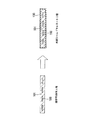
図1は、本発明のフレキシブルフラットケーブルの一実施例を模式的に示す図であり、(a)は上面図、(b)は横断面図である。
本発明のフレキシブルフラットケーブル1は、長尺状の第一平角導体2の横断面方向にから見た周囲に絶縁層3と接着層4とが順に重ねて配されてなる絶縁導体5、長尺状の第二平角導体6からなる接地用導体7、及び、樹脂テープ8と金属テープ9とを貼り合わせてなる絶縁テープ10、を備える。
そして本発明のフレキシブルフラットケーブル1は、前記絶縁導体5と前記接地用導体7とがその幅方向に所定間隔で並べられて配置され、前記金属テープ9側を内側とした前記絶縁テープ10により、その厚み方向から挟まれラミネートされており、前記第一平角導体2及び第二平角導体6の長手方向端部は、所定長さが前記絶縁テープ10の外部に露出していることを特徴とする。
1A and 1B are diagrams schematically showing an embodiment of a flexible flat cable of the present invention, in which FIG. 1A is a top view and FIG. 1B is a cross-sectional view.
The flexible
And the flexible
本発明のフレキシブルフラットケーブル1は、長尺状の絶縁導体5と、長尺状の接地用導体7とが、その幅方向に所定間隔で並べて配置され、絶縁テープ10により、その厚み方向から挟まれラミネートされており、第一平角導体2及び第二平角導体6の長手方向端部は、所定長さが前記絶縁テープ10の外部に露出した構成を有している。これにより、フレキシブルフラットケーブル1は、簡単な構成でシールド性に優れたものとなる。
In the flexible
次に、このようなフレキシブルフラットケーブル1の製造方法について説明する。
本発明のフレキシブルフラットケーブルの製造方法は、長尺状の第一平角導体2の横断面方向から見た周囲に絶縁層3と接着層4とを順に重ねて形成して絶縁導体5とする工程、樹脂テープ8と金属テープ9とを貼り合わせて絶縁テープ10とする工程、前記絶縁導体5と、長尺状の第二平角導体6からなる接地用導体7とを、その幅方向に所定間隔で並べて配置し、前記絶縁導体5及び前記接地用導体7の長手方向端部の所定長さを残して、前記金属テープ9側を内側とした前記絶縁テープ10により、その幅方向から挟んでラミネートする工程、及び、前記絶縁導体5の長手方向端部において、前記絶縁テープ10で挟まれていない部分の絶縁層3及び接着層4を除去して前記第一平角導体2を露出させる工程、を少なくとも備えることを特徴とする。
Next, the manufacturing method of such a flexible
The method for producing a flexible flat cable according to the present invention is a process of forming an
本発明では、前記絶縁導体5と、前記接地用導体7とをその幅方向に所定間隔で並べて配置し、絶縁テープ10により、その厚み方向から挟んでラミネートすることで、ケーブルの作製と外部シールドのラミネートが一工程でできる。また、導体の位置合わせや、接地用導体7と外部シールドとの導通を得るための後加工(絶縁層の切開や、導体の折り返し等)が不要となる。これにより、本発明では、工程を簡略化して作業性を向上させるとともに、工数やコストを削減しつつ、シールド性に優れたフレキシブルフラットケーブル1を製造することができる。
以下、各工程について説明する。
In the present invention, the
Hereinafter, each step will be described.
(1)まず、図2(a)に示すように、長尺状の第一平角導体2の横断面方向から見た周囲に絶縁層3と接着層4とを順に重ねて形成して絶縁導体5とする。
絶縁層3、接着層4の形成方法としては、特に限定されるものではないが、押し出し被覆による塗布方法が、効率が良いため望ましい。
(1) First, as shown in FIG. 2 (a), an
A method for forming the
絶縁層3の材料としては、特に限定されるものではないが、例えば、エナメル、UV樹脂、ポリエチレン樹脂等の絶縁材料が挙げられる。
接着層4の材料としては特に限定されるものではないが、例えばホットメルト、接着剤、溶剤等の接着効果のある材料が挙げられる。
The material of the
Although it does not specifically limit as a material of the contact bonding layer 4, For example, the material with adhesive effects, such as a hot melt, an adhesive agent, and a solvent, is mentioned.
(2)また、図2(b)に示すように、樹脂テープ8と金属テープ9とを貼り合わせて絶縁テープ10とする。
樹脂テープ8の材料としては、特に限定されるものではないが、例えばポリエチレンテレフタレート(PET)等が挙げられる。
金属テープ9の材料としては、特に限定されるものではないが、例えば銅、アルミニウム等、遮蔽効果のある金属材料が挙げられる。
(2) Also, as shown in FIG. 2B, the
Although it does not specifically limit as a material of the
The material of the
(3)次に、図2(c)に示すように、前記絶縁導体5と、長尺状の第二平角導体6からなる接地用導体7とをその幅方向に所定間隔で並べて配置し、前記絶縁導体5及び前記接地用導体7の長手方向端部の所定長さを残して、前記金属テープ9側を内側とした前記絶縁テープ10により、その厚み方向から挟んでラミネートする。
接地用導体7として、加工を施さない裸の平角導体(第二平角導体6)を用意する。
(3) Next, as shown in FIG. 2 (c), the
As the
絶縁導体5と接地用導体7を並べ、導体の長手方向端部における所定長さを残した上で金属テープ9を内側として絶縁テープ10を貼り合わせる。
ラミネート工程は、導体として絶縁導体5及び接地用導体7を用い、あらかじめ決められた位置に接地用導体7を配列し他の導体は絶縁導体5を用いる。これら整線した接地用導体7及び絶縁導体5を金属面を内側として絶縁テープ10で挟み込みラミネートする。
The insulating
In the laminating process, the
図2(d)、(e)は、図1(a)において点線αで囲んだ部分を示す拡大斜視図である。
(4)次に、図2(d)、(e)に示すように、前記絶縁導体5の長手方向端部において、前記絶縁テープ10で挟まれていない部分の絶縁層3及び接着層4を除去して前記第一平角導体2を露出させる。
前記絶縁テープ10で挟まれていない部分の絶縁導体5上の絶縁層3及び接着層4を例えば手作業等により除去し、第一平角導体2を露出させる。
これにより、図1に示すようなフレキシブルフラットケーブル1が作製される。
2D and 2E are enlarged perspective views showing a portion surrounded by a dotted line α in FIG.
(4) Next, as shown in FIGS. 2 (d) and 2 (e), the insulating
The insulating
Thereby, the flexible
このように、本発明では、長尺状の絶縁導体と、長尺状の接地用導体とを幅方向に所定間隔で並べて配置し、絶縁テープにより、その厚み方向から挟んでラミネートすることで、ケーブルの作製と外部シールドのラミネートが一工程でできる。また、導体の位置合わせや、接地用導体と外部シールドとの導通を得るための後加工(絶縁層の切開や、導体の折り返し等)が不要となる。これにより、本発明では、工程を簡略化して作業性を向上させるとともに、工数やコストを削減しつつ、シールド性に優れたフレキシブルフラットケーブルを製造することができる。 As described above, in the present invention, the long insulating conductors and the long grounding conductors are arranged side by side in the width direction at predetermined intervals, and laminated by sandwiching from the thickness direction with the insulating tape, Cable fabrication and external shield lamination can be done in one step. Also, post-processing (insulation layer incision, conductor folding, etc.) for obtaining conductor alignment and electrical connection between the grounding conductor and the external shield is not required. Thereby, in this invention, while simplifying a process and improving workability | operativity, the flexible flat cable excellent in shielding property can be manufactured, reducing a man-hour and cost.
以上、本発明のフレキシブルフラットケーブル及びその製造方法について説明してきたが、本発明はこれに限定されるものではなく、適宜変更可能である。 As mentioned above, although the flexible flat cable and its manufacturing method of this invention were demonstrated, this invention is not limited to this, It can change suitably.
本発明は、フレキシブルフラットケーブルについて広く適用可能である。 The present invention is widely applicable to flexible flat cables.
1 フレキシブルフラットケーブル、2 第一平角導体、3 絶縁層、4 接着層、5 絶縁導体、6 第二平角導体、7 接地用導体、8 樹脂テープ、9 金属テープ、10 絶縁テープ。
DESCRIPTION OF
Claims (2)
長尺状の第二平角導体からなる接地用導体、及び、
樹脂テープと金属テープとを貼り合わせてなる絶縁テープ、を備え、
前記絶縁導体と前記接地用導体とが、その幅方向に所定間隔で並べて配置され、前記金属テープ側を内側とした前記絶縁テープにより、その厚み方向から挟まれラミネートされており、
前記第一平角導体及び第二平角導体の長手方向端部は、所定長さが前記絶縁テープの外部に露出していることを特徴とするフレキシブルフラットケーブル。 An insulating conductor in which an insulating layer and an adhesive layer are sequentially stacked on the periphery as viewed from the cross-sectional direction of the long first flat conductor,
A grounding conductor composed of an elongated second rectangular conductor; and
Insulating tape formed by bonding resin tape and metal tape,
The insulated conductor and the grounding conductor are arranged at predetermined intervals in the width direction, and are sandwiched and laminated from the thickness direction by the insulating tape with the metal tape side inside,
The flexible flat cable is characterized in that the longitudinal ends of the first flat conductor and the second flat conductor have a predetermined length exposed to the outside of the insulating tape.
樹脂テープと金属テープとを貼り合わせて絶縁テープとする工程、
前記絶縁導体と、長尺状の第二平角導体からなる接地用導体とを、その幅方向に所定間隔で並べて配置し、前記絶縁導体及び前記接地用導体の長手方向端部の所定長さを残して、前記金属テープ側を内側とした前記絶縁テープにより、その厚み方向から挟んでラミネートする工程、及び、
前記絶縁導体の長手方向端部において、前記絶縁テープで挟まれていない部分の絶縁層及び接着層を除去して前記第一平角導体を露出させる工程、を少なくとも備えることを特徴とするフレキシブルフラットケーブルの製造方法。 A process in which an insulating layer and an adhesive layer are sequentially stacked around the first cross-sectional direction of the elongated first flat conductor to form an insulating conductor;
The process of bonding resin tape and metal tape to make insulating tape,
The insulated conductor and a grounding conductor made of a long second rectangular conductor are arranged at predetermined intervals in the width direction thereof, and a predetermined length of a longitudinal end portion of the insulated conductor and the grounding conductor is set. Leaving and laminating from the thickness direction by the insulating tape with the metal tape side inside, and,
A flexible flat cable comprising at least a step of exposing the first flat conductor by removing a portion of the insulating layer and the adhesive layer that are not sandwiched by the insulating tape at an end portion in the longitudinal direction of the insulating conductor. Manufacturing method.
Priority Applications (1)
| Application Number | Priority Date | Filing Date | Title |
|---|---|---|---|
| JP2007181126A JP5114119B2 (en) | 2007-07-10 | 2007-07-10 | Flexible flat cable and manufacturing method thereof |
Applications Claiming Priority (1)
| Application Number | Priority Date | Filing Date | Title |
|---|---|---|---|
| JP2007181126A JP5114119B2 (en) | 2007-07-10 | 2007-07-10 | Flexible flat cable and manufacturing method thereof |
Publications (2)
| Publication Number | Publication Date |
|---|---|
| JP2009021044A JP2009021044A (en) | 2009-01-29 |
| JP5114119B2 true JP5114119B2 (en) | 2013-01-09 |
Family
ID=40360535
Family Applications (1)
| Application Number | Title | Priority Date | Filing Date |
|---|---|---|---|
| JP2007181126A Expired - Fee Related JP5114119B2 (en) | 2007-07-10 | 2007-07-10 | Flexible flat cable and manufacturing method thereof |
Country Status (1)
| Country | Link |
|---|---|
| JP (1) | JP5114119B2 (en) |
Families Citing this family (1)
| Publication number | Priority date | Publication date | Assignee | Title |
|---|---|---|---|---|
| JP7238817B2 (en) * | 2020-02-03 | 2023-03-14 | トヨタ自動車株式会社 | Wiring material and its manufacturing method |
Family Cites Families (4)
| Publication number | Priority date | Publication date | Assignee | Title |
|---|---|---|---|---|
| JPS6435617U (en) * | 1987-08-28 | 1989-03-03 | ||
| JP3403075B2 (en) * | 1998-06-30 | 2003-05-06 | 株式会社オートネットワーク技術研究所 | Flat cable and manufacturing method thereof |
| JP4374229B2 (en) * | 2003-10-01 | 2009-12-02 | 矢崎総業株式会社 | Manufacturing method of flat shielded cable |
| JP2006156079A (en) * | 2004-11-29 | 2006-06-15 | Matsushita Electric Ind Co Ltd | Flexible flat cable |
-
2007
- 2007-07-10 JP JP2007181126A patent/JP5114119B2/en not_active Expired - Fee Related
Also Published As
| Publication number | Publication date |
|---|---|
| JP2009021044A (en) | 2009-01-29 |
Similar Documents
| Publication | Publication Date | Title |
|---|---|---|
| US6624359B2 (en) | Multifolded composite tape for use in cable manufacture and methods for making same | |
| JP5491906B2 (en) | Bundled flexible wiring | |
| JP4506818B2 (en) | Manufacturing method of shielded flat cable | |
| TWI453768B (en) | Composite flexible circuit cable | |
| US10964448B1 (en) | High density ribbon cable | |
| US9663045B2 (en) | Wiring harness and method for manufacturing the same | |
| JP2011066379A5 (en) | ||
| CN110383396A (en) | Shielding flat cable | |
| US10176906B2 (en) | Shielded conductive path | |
| KR20100071437A (en) | Electro magnetic shielding tube | |
| JP2011146150A (en) | Shielded flat cable | |
| JP2015130276A (en) | Shielded wire | |
| CN104347162A (en) | Flat cable and method for manufacturing same | |
| JP6439306B2 (en) | Flat cable and manufacturing method thereof | |
| JP5114119B2 (en) | Flexible flat cable and manufacturing method thereof | |
| JP4517612B2 (en) | Bend-resistant shield-coated flexible flat cable and method for manufacturing the same | |
| JP5114152B2 (en) | Flexible flat cable and manufacturing method thereof | |
| JP2014146506A (en) | Wire harness | |
| JP2010165561A (en) | Shielded flat cable and method of manufacturing the same | |
| JP5954165B2 (en) | Wire harness | |
| JP2014154244A (en) | Method for manufacturing a shield-clad flexible flat cable and shield-clad flexible flat cable | |
| JP2003045241A (en) | Shielded flat electric wire and manufacturing method thereof | |
| CN109637894B (en) | Self-locking binding method for relay coil | |
| JPH06243730A (en) | Shielded flat cable | |
| US20110253416A1 (en) | Semi-bonded shielding in a coaxial cable |
Legal Events
| Date | Code | Title | Description |
|---|---|---|---|
| A621 | Written request for application examination |
Free format text: JAPANESE INTERMEDIATE CODE: A621 Effective date: 20100607 |
|
| TRDD | Decision of grant or rejection written | ||
| A01 | Written decision to grant a patent or to grant a registration (utility model) |
Free format text: JAPANESE INTERMEDIATE CODE: A01 Effective date: 20120918 |
|
| A01 | Written decision to grant a patent or to grant a registration (utility model) |
Free format text: JAPANESE INTERMEDIATE CODE: A01 |
|
| A61 | First payment of annual fees (during grant procedure) |
Free format text: JAPANESE INTERMEDIATE CODE: A61 Effective date: 20121015 |
|
| FPAY | Renewal fee payment (event date is renewal date of database) |
Free format text: PAYMENT UNTIL: 20151019 Year of fee payment: 3 |
|
| FPAY | Renewal fee payment (event date is renewal date of database) |
Free format text: PAYMENT UNTIL: 20151019 Year of fee payment: 3 |
|
| LAPS | Cancellation because of no payment of annual fees |