JP5115655B2 - Vehicle control device - Google Patents
Vehicle control device Download PDFInfo
- Publication number
- JP5115655B2 JP5115655B2 JP2011514233A JP2011514233A JP5115655B2 JP 5115655 B2 JP5115655 B2 JP 5115655B2 JP 2011514233 A JP2011514233 A JP 2011514233A JP 2011514233 A JP2011514233 A JP 2011514233A JP 5115655 B2 JP5115655 B2 JP 5115655B2
- Authority
- JP
- Japan
- Prior art keywords
- cabin
- sensor
- vehicle
- opening
- detection unit
- Prior art date
- Legal status (The legal status is an assumption and is not a legal conclusion. Google has not performed a legal analysis and makes no representation as to the accuracy of the status listed.)
- Expired - Fee Related
Links
Images



Classifications
-
- G—PHYSICS
- G01—MEASURING; TESTING
- G01P—MEASURING LINEAR OR ANGULAR SPEED, ACCELERATION, DECELERATION, OR SHOCK; INDICATING PRESENCE, ABSENCE, OR DIRECTION, OF MOVEMENT
- G01P21/00—Testing or calibrating of apparatus or devices covered by the preceding groups
-
- B—PERFORMING OPERATIONS; TRANSPORTING
- B62—LAND VEHICLES FOR TRAVELLING OTHERWISE THAN ON RAILS
- B62D—MOTOR VEHICLES; TRAILERS
- B62D33/00—Superstructures for load-carrying vehicles
- B62D33/06—Drivers' cabs
- B62D33/063—Drivers' cabs movable from one position into at least one other position, e.g. tiltable, pivotable about a vertical axis, displaceable from one side of the vehicle to the other
- B62D33/067—Drivers' cabs movable from one position into at least one other position, e.g. tiltable, pivotable about a vertical axis, displaceable from one side of the vehicle to the other tiltable
- B62D33/07—Drivers' cabs movable from one position into at least one other position, e.g. tiltable, pivotable about a vertical axis, displaceable from one side of the vehicle to the other tiltable characterised by the device for locking the cab in the tilted or in the driving position
- B62D33/071—Locking devices for cabins in driving position; Shock and vibration absorbing devices therefor
Landscapes
- Engineering & Computer Science (AREA)
- Physics & Mathematics (AREA)
- General Physics & Mathematics (AREA)
- Chemical & Material Sciences (AREA)
- Combustion & Propulsion (AREA)
- Transportation (AREA)
- Mechanical Engineering (AREA)
- Vehicle Body Suspensions (AREA)
- Control Of Driving Devices And Active Controlling Of Vehicle (AREA)
Description
本発明は、軸周りに可動する可動部を有する車両を制御する車両制御装置に関する。 The present invention relates to a vehicle control device that controls a vehicle having a movable part that is movable around an axis.
従来の車両制御装置として、車両内に取り付けられた加速度センサの出力値をモニタリングし、当該出力値を種々のシステムに適用するものが知られている(例えば、特許文献1参照)。この車両制御装置では、車両に取り付けられた加速度センサがエラーを有しているかを検出することができる。 As a conventional vehicle control device, one that monitors an output value of an acceleration sensor mounted in a vehicle and applies the output value to various systems is known (for example, see Patent Document 1). In this vehicle control device, it is possible to detect whether an acceleration sensor attached to the vehicle has an error.
ここで、可動式のキャビンを大型トラックなどのように、可動部を有する車両に加速度センサなどの車両運動状態量センサを適用する場合、加速度センサの搭載環境(例えば、水、泥入り、飛石防止のため)によって、あるいはエアバッグECUなどの他部品へのセンサ内蔵化によって、キャビン内へ加速度センサが搭載されることが考えられる。しかしながら、キャビンに加速度センサを搭載した場合は、キャビンを開いて傾けた際に加速度センサも共に傾くため、停車中にも関わらず大きな傾きに対応した出力値を出力してしまう。このように停車中にも関らず過大な出力値が検出されると、VSCやセンサ信号を利用する車両制御システムがセンサ出力の異常と誤検出してしまう場合がある。更に、キャビンを一度開いた場合は再び閉じたときに加速度センサの傾きが微妙にずれてしまうことによって補正を行ったとしても最適な制御を行えない可能性があった。このように、従来の車両制御装置にあっては、加速度センサなどの車両運動状態量センサを車両の可動部に登載した場合に種々の問題を生じ、適切な制御を行えなくなるという問題がある。 Here, when a vehicle motion state quantity sensor such as an acceleration sensor is applied to a vehicle having a movable part such as a large truck with a movable cabin, the environment in which the acceleration sensor is installed (for example, water, mud entry, stepping stone prevention) Therefore, it is conceivable that the acceleration sensor is mounted in the cabin by incorporating the sensor into other components such as an airbag ECU. However, when the acceleration sensor is mounted on the cabin, the acceleration sensor is tilted when the cabin is opened and tilted, so that an output value corresponding to a large tilt is output even when the vehicle is stopped. As described above, when an excessive output value is detected even when the vehicle is stopped, the vehicle control system using the VSC or the sensor signal may erroneously detect a sensor output abnormality. Furthermore, when the cabin is opened once, the inclination of the acceleration sensor slightly deviates when the cabin is closed again, so that there is a possibility that optimum control cannot be performed even if correction is performed. As described above, the conventional vehicle control apparatus has a problem that various problems occur when a vehicle motion state quantity sensor such as an acceleration sensor is mounted on the movable portion of the vehicle, and appropriate control cannot be performed.
本発明は、このような問題を解決するためになされたものであり、車両の可動部に加速度センサを搭載した場合であっても、適切な制御を行うことのできる車両制御装置を提供することを目的とする。 The present invention has been made to solve such a problem, and provides a vehicle control apparatus capable of performing appropriate control even when an acceleration sensor is mounted on a movable part of the vehicle. With the goal.
本発明に係る車両制御装置は、軸周りに可動するキャビンに取り付けられた車両運動状態量センサと、キャビンの開閉を検出する開閉検出ユニットと、車両運動状態量センサの出力値に対して補正を行う補正ユニットと、を備え、開閉検出ユニットによって、キャビンが開いた後に閉じたことを検出された際に、補正ユニットは補正を行うことを特徴とする。 A vehicle control apparatus according to the present invention corrects a vehicle motion state quantity sensor attached to a cabin movable around an axis, an open / close detection unit that detects opening / closing of a cabin, and an output value of the vehicle motion state quantity sensor. A correction unit that performs correction when the opening / closing detection unit detects that the cabin has been closed after being opened.
また、本発明に係る車両制御装置は、軸周りに可動する可動部に取り付けられた車両運動状態量センサと、可動部が所定位置から動いたことを検出する検出ユニットと、車両運動状態量センサの出力値に対して補正を行う補正ユニットと、を備え、検出ユニットによって、可動部が所定位置から動いた後に所定位置に戻ったことを検出された際に、補正ユニットは補正を行うことを特徴とする。 In addition, a vehicle control device according to the present invention includes a vehicle motion state quantity sensor attached to a movable part movable around an axis, a detection unit that detects that the movable part has moved from a predetermined position, and a vehicle motion state quantity sensor. A correction unit that corrects the output value, and the correction unit performs correction when the detection unit detects that the movable portion has returned from the predetermined position and then returned to the predetermined position. Features.
この車両制御装置では、開閉検出ユニット(検出ユニット)によって可動部であるキャビンが開いた後に閉じたこと(すなわち所定位置から動いた後に所定位置に戻ったこと)を検出された際に、補正ユニットが補正を行う。可動部であるキャビンに車両運動状態量センサが設けられている場合は、一度キャビンを開いて閉じた場合、車両運動状態量センサの傾きは開く前と開いた後では微小ながらも異なっている可能性がある。例えば、キャビンを開く前と開いた後とで同様な補正値を用いてセンサ出力演算を行った場合は正確な制御が行えない可能性がある。また、車両の停車中にキャビンが開いている間も常時補正値を変化させて補正を行った場合は、無用な演算を行うこととなってしまい、制御負荷が増加してしまう。従って、キャビンが開いた後に閉じた際に補正を行うことによって、制御の負荷を低減すると共に、新たな車両運動状態量センサの傾きに従った正確な制御を行うことができる。以上によって、車両の可動部であるキャビンに車両運動状態量センサを搭載した場合であっても、適切な制御を行うことができる。 In this vehicle control device, when the opening / closing detection unit (detection unit) detects that the cabin, which is a movable part, has been opened and closed (that is, moved from a predetermined position and then returned to the predetermined position), the correction unit Corrects. When a vehicle motion state sensor is provided in a cabin that is a movable part, when the cabin is opened and closed once, the inclination of the vehicle motion state sensor may be slightly different before and after opening. There is sex. For example, when the sensor output calculation is performed using the same correction value before and after opening the cabin, there is a possibility that accurate control cannot be performed. Further, when correction is performed by changing the correction value constantly while the cabin is open while the vehicle is stopped, useless calculation is performed, and the control load increases. Therefore, by performing correction when the cabin is closed after being opened, it is possible to reduce the control load and perform accurate control according to the inclination of the new vehicle motion state sensor. As described above, appropriate control can be performed even when the vehicle motion state sensor is mounted on the cabin which is the movable part of the vehicle.
本発明に係る車両制御装置は、軸周りに可動するキャビンに取り付けられた車両運動状態量センサと、キャビンの開閉を検出する開閉検出ユニットと、車両運動状態量センサの異常を検出する異常検出ユニットと、を備え、開閉検出ユニットによって、キャビンが開いていることを検出された場合、異常検出ユニットの異常検出が禁止されることを特徴とする。 A vehicle control device according to the present invention includes a vehicle motion state sensor attached to a cabin movable around an axis, an open / close detection unit that detects opening / closing of a cabin, and an abnormality detection unit that detects an abnormality of the vehicle motion state sensor. When the opening / closing detection unit detects that the cabin is open, abnormality detection of the abnormality detection unit is prohibited.
この車両制御装置では、開閉検出ユニットによって、キャビンが開いていることを検出された場合、異常検出ユニットの異常検出が禁止される。これによって、停車中にキャビンを可動させることで車両運動状態量センサが大きく傾いた場合であっても、異常検出ユニットが誤って異常を検出してしまうことを防止することができる。以上によって、車両の可動部であるキャビンに車両運動状態量センサを搭載した場合であっても、適切な制御を行うことができる。 In this vehicle control device, when the opening / closing detection unit detects that the cabin is open, the abnormality detection unit prohibits the abnormality detection. Accordingly, even when the vehicle motion state quantity sensor is largely inclined by moving the cabin while the vehicle is stopped, it is possible to prevent the abnormality detection unit from erroneously detecting the abnormality. As described above, appropriate control can be performed even when the vehicle motion state sensor is mounted on the cabin which is the movable part of the vehicle.
本発明に係る車両制御装置は、軸周りに可動するキャビンに取り付けられた車両運動状態量センサと、キャビンの開閉を検出する開閉検出ユニットと、車両運動状態量センサの出力値に基づいて演算を行う演算ユニットと、を備え、開閉検出ユニットによってキャビンが開いていることを検出されている間、演算ユニットは車両運動状態量センサのセンサ出力演算値として、キャビンが開く前のセンサ出力演算値を保持することを特徴とする。 A vehicle control device according to the present invention performs a calculation based on a vehicle motion state quantity sensor attached to a cabin movable around an axis, an open / close detection unit that detects opening / closing of a cabin, and an output value of the vehicle motion state quantity sensor. An arithmetic unit that performs a sensor output calculation value before the cabin is opened as the sensor output calculation value of the vehicle motion state amount sensor while the opening / closing detection unit detects that the cabin is open. It is characterized by holding.
この車両制御装置では、開閉検出ユニットによってキャビンが開いていることを検出されている間、演算ユニットは、車両運動状態量センサのセンサ出力演算値として、キャビンが開く前の車両運動状態量センサのセンサ出力演算値を保持することができる。これによって、停車中にキャビンを可動させて車両運動状態量センサが大きく傾くことで、実際の車両運動状態量センサからの出力値が大きく変動してしまった場合であっても、キャビンが開く前のセンサ出力演算値を用いることにより、誤って異常検出されることや、他のシステムが誤作動してしまうことを防止することができる。 In this vehicle control device, while the opening / closing detection unit detects that the cabin is open, the calculation unit uses the vehicle movement state quantity sensor before the cabin is opened as the sensor output calculation value of the vehicle movement state quantity sensor. The sensor output calculation value can be held. As a result, even if the output value from the actual vehicle motion state sensor greatly fluctuates by moving the cabin while the vehicle is stopped and the vehicle motion state sensor greatly tilts, By using this sensor output calculation value, it is possible to prevent erroneous detection of an error or malfunction of another system.
本発明によれば、車両の可動部に車両運動状態量センサを搭載した場合であっても、適切な制御を行うことができる。 According to the present invention, appropriate control can be performed even when the vehicle motion state sensor is mounted on the movable part of the vehicle.
以下、図面を参照して本発明に係る車両制御装置に好適な実施形態について詳細に説明する。 DESCRIPTION OF EXEMPLARY EMBODIMENTS Hereinafter, preferred embodiments of a vehicle control device according to the invention will be described in detail with reference to the drawings.
図1は、本発明の実施形態に係る車両制御装置1のブロック構成を示した図である。車両制御装置1は、大型トラックなどのように、軸2周りに可動するキャビン3を備えた車両M1に搭載される制御装置である。車両M1において、通常時、キャビン3は底面が略水平となるように土台4に載せられるが(この状態を以下、キャビン3が閉じている状態とする)、メンテナンスを行う場合、キャビン3は軸2周りに上側へ可動されて傾けられる(この状態を以下、キャビン3が開いている状態とする)。車両制御装置1は、VSC(Vehicle Stability Control)センサ5、ECU(Electronic Control Unit)7を備えて構成されている。
FIG. 1 is a diagram showing a block configuration of a
VSCセンサ5は、加速度センサ(車両運動状態量センサ)6を備えており、更に、ヨーレイトセンサ、操舵角センサ、車速センサなどの各種センサを含んで構成されている。このVSCセンサ5、加速度センサ6は、車両M1のキャビン3に搭載されており、キャビン3が閉じている状態では水平に保たれるが、キャビン3が開いている状態では水平に対して傾けられる。VSCセンサ5、加速度センサ6は、検出した各種情報をECU7へ出力する機能を有している。
The
ECU7は、車両制御装置1全体の制御を行う電子制御ユニットであり、例えばCPUを主体として構成され、ROM、RAM、入力信号回路、出力信号回路、電源回路などを備えている。このECU7は、VSCセンサ5と同じく車両M1のキャビン3に搭載されている。ECU7は、開閉検出部(開閉検出ユニット、検出ユニット)11、演算部(演算ユニット)12、補正部(補正ユニット)13、異常検出部(異常検出ユニット)14を備えて構成されている。
The ECU 7 is an electronic control unit that controls the entire
開閉検出部11は、キャビン3の開閉を検出する機能を有する。この開閉検出部11は、例えば、土台4に設けられてキャビン3が開いたときに解除されるスイッチセンサの出力信号や、キャビン3の傾斜角に基づいて、キャビン3の開閉を検出することができる。
The open /
演算部12は、VSCセンサ5の出力値に基づいて各種演算を行う機能を有している。この演算部12は、キャビン3が閉じているときは、現在の実際の加速度センサ6の出力値をセンサ出力演算値として設定する機能を有している。一方、演算部12は、開閉検出部11によってキャビン3が開いていることを検出されている間、加速度センサ6のセンサ出力演算値として、キャビン3が開く前のセンサ出力演算値を保持する機能を有している。具体的には、演算部12は、キャビン3が開く直前における加速度センサ6のセンサ出力演算値をセットすると共に、キャビン3が開いている間は、当該値をセンサ出力演算値として設定し続ける。
The
補正部13は、加速度センサ6のセンサ出力演算値に対して補正を行う機能を有している。この補正部13は、車両M1が停止している状態(車速センサの出力値がゼロである状態)での出力値をオフセット値(センサ補正値)として算出し、加速度センサ6からの出力値と補正値との差分に加速度センサ6の感度を乗算することで補正を行っている。これは一般的にゼロ点補正を呼ばれている。なお、補正部13はゼロ点補正のみならずゲインの補正など、各種補正処理を行う機能を有している。また、補正部13は、開閉検出部11によって、キャビン3が開いた後に再び閉じたことを検出された際、補正を行う機能を有している。具体的に、補正部13は、キャビン3が開いたときには既にセットされているセンサ補正値を一度リセットし、キャビン3が再び閉じたときに再度新たなセンサ補正値をセットする。また、補正部13は、キャビン3が開いているときは補正を禁止すると共に、再びキャビン3が閉じたときに補正を許可する機能を有している。
The
異常検出部14は、VSCセンサ5、加速度センサ6の異常を検出する機能を有しており、例えばセンサ出力値が高くなりすぎている場合にセンサ異常であると検出する機能を有している。異常検出部14は、キャビン3が開いているときは異常検出を禁止すると共に、再びキャビン3が閉じたときに異常検出を許可する機能を有している。
The
次に、図2を参照して本実施形態に係る車両制御装置1の動作について説明する。図2は、本実施形態に係る車両制御装置1における制御処理を示すフローチャートである。この処理は、ECU7において車両M1の停車中、所定のタイミングで実行される。
Next, the operation of the
図2に示すように、車両制御装置1の開閉検出部11は、車両M1のキャビン3の開閉を検出する(ステップS10)。次に、開閉検出部11は、S10の検出結果に基づいて、キャビン3が閉じているか否かの判定を行う(ステップS12)。
As shown in FIG. 2, the opening /
S12においてキャビン3が開いていると判定された場合、演算部12は、キャビン3が開く前の加速度センサ6のセンサ出力演算値が既にセットされているか否かの判定を行う(ステップS14)。この出力値は、キャビン3が開く直前の、閉じている状態における加速度センサ6のセンサ出力演算値であり、以下「キャビン開前出力値」と称する。キャビン3が開いた直後の処理ではキャビン開前出力値は設定されておらず、一度設定された後は、キャビン3が開いている間、キャビン開前出力値が設定されていると判定される。S14において、キャビン開前出力値がセットされていないと判定された場合、演算部12は、直前に演算したセンサ出力演算値をキャビン開前出力値としてセットする(ステップS16)。
When it is determined in S12 that the
S14においてキャビン開前出力値がセットされていると判定された場合、またはS16の処理が終了した場合、補正部13は、加速度センサのセンサ補正を禁止する(ステップS18)。また、異常検出部14は、加速度センサのセンサ異常の検出を禁止する(ステップS20)。次に、補正部13は、現在設定されているセンサ補正値のリセットを行う(ステップS22)。その後、演算部12は、キャビン開前出力値をセンサ出力演算値として設定する(ステップS24)。これによって、開閉検出部11によってキャビン3が開いていることを検出されている間、演算部12は、加速度センサの出力演算値として、キャビン3が開く前のセンサ出力演算値を保持することができる。S24の処理が終了すると、図2に示す制御処理は終了し、S10から再び処理をスタートする。
When it is determined in S14 that the output value before opening of the cabin is set, or when the processing of S16 is completed, the
一方、キャビン3が開く前の状態、あるいはキャビン3が開いて再び閉じた状態では、S12においてキャビン3が閉じていると判定される。この場合、演算部12は、キャビン3が開いているときにS16でセットされたキャビン開前出力値をリセットする(ステップS26)。次に、補正部13は、加速度センサのセンサ補正を許可する(ステップS28)。また、異常検出部14は、加速度センサのセンサ異常の検出を許可する(ステップS30)。
On the other hand, in a state before the
次に、補正部13は、センサ補正値のセットを行う(ステップS32)。なお、S22の処理では、キャビン3が閉じた直後の処理であれば新たな補正値が再セットされるが、キャビン3が閉じられ続けている状態での処理であれば、既にセットされている補正値を用いることとし、S32の処理を省略することもできる。その後、演算部12は、現在の加速度センサの実際の出力値をセンサ出力演算値として設定する(ステップS34)。S34の処理が終了すると、図2に示す制御処理は終了し、S10から再び処理をスタートする。
Next, the
以上によって、本実施形態に係る車両制御装置1によれば、開閉検出部11によって、キャビン3が開いた後に閉じたことを検出された際、補正部13は補正を行うことができる。可動部であるキャビン3に加速度センサ6が設けられている場合は、一度キャビン3を開いて閉じた場合、加速度センサ6の傾きは開く前と開いた後では微小ながらも異なっている可能性がある。例えば、キャビン3を開く前と開いた後とで同様な補正値を用いてセンサ出力演算を行った場合は正確な制御が行えない可能性がある。また、車両M1の停車中にキャビン3が開いている間も常時補正を行った場合は、無用な演算を行うこととなってしまい、制御負荷が増加してしまう。従って、キャビン3が開いた後に閉じた際に補正を行うことによって、制御の負荷を低減すると共に、新たな加速度センサ6の傾きに従った正確な制御を行うことができる。以上によって、車両M1の可動部であるキャビン3に加速度センサ6を搭載した場合であっても、適切な制御を行うことができる。
As described above, according to the
また、本実施形態に係る車両制御装置1によれば、開閉検出部11によってキャビン3が開いていることを検出された場合、異常検出部14は異常検出を禁止することができる。これによって、停車中にキャビン3を可動させることで加速度センサ6が大きく傾いた場合であっても、異常検出部14が誤って異常を検出してしまうことを防止することができる。以上によって、車両M1の可動部であるキャビン3に加速度センサ6を搭載した場合であっても、適切な制御を行うことができる。
In addition, according to the
また、本実施形態に係る車両制御装置1によれば、開閉検出部11によってキャビン3が開いていることを検出されている間、演算部12は、加速度センサ6のセンサ出力演算値として、キャビン3が開く前の加速度センサ6のセンサ出力演算値を保持することができる。これによって、停車中にキャビン3を可動させて加速度センサ6が大きく傾くことで、実際の加速度センサ6からの出力値が大きく変動してしまった場合であっても、キャビンが開く前のセンサ出力演算値を用いることにより、誤って異常検出されることや、他のシステムが誤作動してしまうことを防止することができる。
Further, according to the
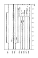
次に、本実施形態に係る車両制御装置1の実施例を従来の車両制御装置と比較して説明する。図3は、従来の車両制御装置を用いて制御を行った場合における、各出力値や異常検出のフラグの状態を示した線図である。図4は、本実施形態に係る車両制御装置1を用いて制御を行った場合における、各出力値や異常検出のフラグの状態を示した線図である。図3及び図4では、線図LA1,LB1がキャビン3の開閉状態を示しており、線が下段にあるときはキャビン3が閉じている状態を示し、線が上段にあるときはキャビン3が開いている状態を示す。線図LA2,LB2は加速度センサ6の実際の出力値に基づいて演算部12が演算したセンサ出力演算値を示している。線図LA3,LB3は異常検出部14による異常検出が許可されているか禁止されているかを示しており、線が下段にあるときは異常検出が禁止されており、線が上段にあるときは異常検出が許可されている状態を示す。線図LA4,LB4はセンサ異常カウンタを示しており、異常検出部14が加速度センサ6の異常を検出するためにカウントしている値を示している。線図LA5,LB5は異常検出部14によるセンサ異常フラグを示しており、異常がないときは線が下段に存在し、異常が検出されたときにフラグが立って線が上段に移動する。線図LA6,LB6はヨーレイトを示し、線図LA7,LB7は舵角を示し、線図LA8,LB8は車体速度を示している。図3及び図4では、車両M1が停車し、7〜10秒付近でキャビン3を開いて、37〜40秒付近でキャビン3を閉じた場合の各線図が示されている。なお、車両M1が停車中であるため、ヨーレイト、舵角、車体速度は変化しない。
Next, an example of the
従来の車両制御装置は、加速度センサ6のセンサ出力演算値として実際の加速度センサ6の出力値を用い、異常検出部14の異常検出も禁止されていない。よって、図3の線図LA2に示すように、センサ出力演算値はキャビン3が開くのに従って増加し、キャビン3が閉まるのに従って減少する。また、線図LA3に示すように、キャビン3の開閉に関わらず常時、異常検出が許可される。従って、線図LA4に示すように、キャビン3が開いた後、センサ出力演算値に従ってセンサ異常カウンタは増加し(図中、PA1で示す)、センサ異常カウンタが一定以上増加したところでセンサ異常フラグが立ち上がり(図中、PA2で示す)、センサ異常検出が成立する。このように、従来の車両制御装置は、車両M1が停車中にキャビン3を開閉したときに、誤ってセンサ異常を検出してしまう。
The conventional vehicle control device uses the actual output value of the acceleration sensor 6 as the sensor output calculation value of the acceleration sensor 6, and the abnormality detection of the
一方、本実施形態に係る車両制御装置1は、キャビン3が開いている間、加速度センサ6のセンサ出力演算値として、キャビン3が開く前のセンサ出力演算値を用い、異常検出を禁止することができる。従って、図4の線図LB2に示すように、センサ出力演算値はキャビン3の開閉によらず一定となる(図中、PB1で示す)。また、線図LB3に示すように、キャビン3が開いたときに加速度センサ6の異常検出が禁止される(図中、PB2で示す)。これによって、線図LB4に示すように、キャビン3が開いた後もセンサ異常カウンタは増加せず(図中、PB3で示す)、線図LB5に示すように、センサ異常フラグも立ち上がらない(図中、PB4で示す)。以上のように、本実施形態に係る車両制御装置1では、キャビン3に加速度センサ6を取り付けてキャビン3を開閉した場合であっても、誤ってセンサ異常を検出することを防止できる。
On the other hand, the
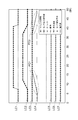
図5は、従来の車両制御装置を用いて制御を行った場合における、各出力値や補正値の状態を示した線図である。図6は、本実施形態に係る車両制御装置1を用いて制御を行った場合における、各出力値や補正値の状態を示した線図である。図5及び図6では、線図LC1,LD1がキャビン3の開閉状態を示しており、線が下段にあるときはキャビン3が閉じている状態を示し、線が上段にあるときはキャビン3が空いている状態を示す。線図LC2,LD2は加速度センサ6の実際の出力値に基づいて演算部12が演算したセンサ出力演算値を示している。線図LC3,LD3は補正部13による補正が許可されているか禁止されているかを示しており、線が下段にあるときは補正が禁止されており、線が上段にあるときは補正が許可されている状態を示す。線図LC4,LD4は補正値を示している。線図LC5,LD5はヨーレイトを示し、線図LC6,LD6は舵角を示し、線図LC7,LD7は車体速度を示している。図5及び図6では、車両M1が停車し、7〜10秒付近でキャビン3を開いて、37〜40秒付近でキャビン3を閉じた場合の各線図が示されている。なお、車両M1が停車中であるため、ヨーレイト、舵角、車体速度は変化しない。
FIG. 5 is a diagram showing the state of each output value and correction value when control is performed using a conventional vehicle control device. FIG. 6 is a diagram showing states of output values and correction values when control is performed using the
従来の車両制御装置は、補正部13の補正が禁止されておらず、補正値もセンサ出力演算値によって変化する。よって、図5の線図LC3に示すように、キャビン3の開閉に関わらず常時、補正が許可される。従って、線図LC4に示すように、キャビン3が開いた後、センサ出力演算値に従って補正値は増加し(図中、PC1で示す)、このように、従来の車両制御装置は、車両M1が停車中にキャビン3を開閉したときに、無用に補正値を変化させてしまい、制御の負荷が増加してしまう。
In the conventional vehicle control device, the correction of the
一方、本実施形態に係る車両制御装置1は、キャビン3が開いている間、補正を禁止すると共に、キャビン3が再び閉じたタイミングで補正することができる。なお、本実施形態における車両制御装置1の補正の効果を独立で検証すべく、LD2に示すように、センサ出力演算値は実際の加速度センサ6の出力値に従うものとする。図6の線図LD3に示すように、キャビン3が開いたときに補正が禁止される(図中、PD1で示す)。更に、線図LD4に示すように補正値がリセットされる。そして、キャビン3が再び閉じたタイミングで補正が許可され、新たな補正値がセットされる(図中、PD2で示す)。これによって、キャビン3に加速度センサ6を取り付けてキャビン3を開閉した場合に、制御の負荷を低減すると共に、新たな加速度センサ6の傾きに従った正確な制御を行うことができる。
On the other hand, the
本発明は、上述した実施形態に限定されるものではない。 The present invention is not limited to the embodiment described above.
例えば、上述の実施形態では車両の可動部の一例として、大型トラックのキャビンに加速度センサを搭載した場合について説明したが、これに限定されず、可動する部分に加速度センサを搭載したどのような車両に対しても適用することができる。 For example, in the above-described embodiment, the case where the acceleration sensor is mounted on the cabin of a large truck as an example of the movable portion of the vehicle has been described. However, the present invention is not limited thereto, and any vehicle in which the acceleration sensor is mounted on the movable portion It can also be applied to.
また、上述の実施形態では、車両制御装置は、開閉検出部11によってキャビン3が開いた後に閉じたことを検出された際に補正部13が補正を行う機能、開閉検出部11によってキャビン3が開いていることを検出された場合に異常検出部14の異常検出が禁止される機能、及び開閉検出部11によってキャビン3が開いていることを検出されている間に演算部12が加速度センサ6の出力値としてキャビン3が開く前の出力値を保持する機能を全て有しているが、これに代えて、いずれか一つの機能のみを有しているものであってもよい。
Further, in the above-described embodiment, the vehicle control device has a function in which the
また、上述の実施形態では、車両運動状態量センサの一例として加速度センサの場合について説明したが、この車両運動状態量センサは、ピッチ、バランス、ヨー、ロール、ヨーレート、ローレートなどの運動状態を示す物理量を検出するセンサであって、少なくともキャビンの開閉に応じて出力値が変わりうるセンサであればどのようなものも含まれる。 In the above-described embodiment, the case of the acceleration sensor is described as an example of the vehicle motion state quantity sensor. However, the vehicle motion state quantity sensor indicates a motion state such as pitch, balance, yaw, roll, yaw rate, or low rate. Any sensor that detects a physical quantity and that can change an output value in accordance with at least opening / closing of a cabin is included.
本発明は、車両の可動部に加速度センサを搭載した場合、適切な制御を行う際に利用可能である。 The present invention can be used when appropriate control is performed when an acceleration sensor is mounted on a movable part of a vehicle.
1…車両制御装置、2…軸、3…キャビン、6…加速度センサ(車両運動状態量センサ)、11…開閉検出部(開閉検出ユニット,検出ユニット)、12…演算部(演算ユニット)、13…補正部(補正ユニット)、14…異常検出部(異常検出ユニット)。
DESCRIPTION OF
Claims (3)
前記キャビンの開閉を検出する開閉検出ユニットと、
前記車両運動状態量センサの出力値に対して補正を行う補正ユニットと、
前記車両運動状態量センサの出力値に基づいて演算を行う演算ユニットと、を備え、
前記開閉検出ユニットによって、前記キャビンが開いた後に閉じたことを検出された際に、前記補正ユニットは補正を行い、
前記開閉検出ユニットによって、前記キャビンが開いていることを検出されている間、前記演算ユニットは、前記車両運動状態量センサのセンサ出力演算値として、前記キャビンが開く前の前記センサ出力演算値を保持することを特徴とする車両制御装置。A vehicle motion state sensor attached to a cabin movable around an axis;
An opening / closing detection unit for detecting opening / closing of the cabin;
A correction unit for correcting the output value of the vehicle motion state quantity sensor;
An arithmetic unit that performs an operation based on an output value of the vehicle movement state quantity sensor,
When the opening / closing detection unit detects that the cabin is closed after being opened, the correction unit performs correction,
While the opening / closing detection unit detects that the cabin is open, the calculation unit uses the sensor output calculation value before the cabin is opened as the sensor output calculation value of the vehicle motion state sensor. A vehicle control device characterized by holding.
前記キャビンの開閉を検出する開閉検出ユニットと、
前記車両運動状態量センサの異常を検出する異常検出ユニットと、
前記車両運動状態量センサの出力値に基づいて演算を行う演算ユニットと、を備え、
前記開閉検出ユニットによって、前記キャビンが開いていることを検出された場合、前記異常検出ユニットの異常検出が禁止され、
前記開閉検出ユニットによって、前記キャビンが開いていることを検出されている間、前記演算ユニットは、前記車両運動状態量センサのセンサ出力演算値として、前記キャビンが開く前の前記センサ出力演算値を保持することを特徴とする車両制御装置。A vehicle motion state sensor attached to a cabin movable around an axis;
An opening / closing detection unit for detecting opening / closing of the cabin;
An abnormality detection unit for detecting an abnormality of the vehicle motion state quantity sensor;
An arithmetic unit that performs an operation based on an output value of the vehicle movement state quantity sensor,
When the opening / closing detection unit detects that the cabin is open, the abnormality detection of the abnormality detection unit is prohibited,
While the opening / closing detection unit detects that the cabin is open, the calculation unit uses the sensor output calculation value before the cabin is opened as the sensor output calculation value of the vehicle motion state sensor. A vehicle control device characterized by holding.
前記キャビンの開閉を検出する開閉検出ユニットと、
前記車両運動状態量センサの出力値に基づいて演算を行う演算ユニットと、を備え、
前記開閉検出ユニットによって、前記キャビンが開いていることを検出されている間、前記演算ユニットは、前記車両運動状態量センサのセンサ出力演算値として、前記キャビンが開く前の前記センサ出力演算値を保持することを特徴とする車両制御装置。A vehicle motion state sensor attached to a cabin movable around an axis;
An opening / closing detection unit for detecting opening / closing of the cabin;
An arithmetic unit that performs an operation based on an output value of the vehicle movement state quantity sensor,
While the opening / closing detection unit detects that the cabin is open, the calculation unit uses the sensor output calculation value before the cabin is opened as the sensor output calculation value of the vehicle motion state sensor. A vehicle control device characterized by holding.
Applications Claiming Priority (1)
| Application Number | Priority Date | Filing Date | Title |
|---|---|---|---|
| PCT/JP2009/059133 WO2010134152A1 (en) | 2009-05-18 | 2009-05-18 | Vehicle controller |
Publications (2)
| Publication Number | Publication Date |
|---|---|
| JPWO2010134152A1 JPWO2010134152A1 (en) | 2012-11-08 |
| JP5115655B2 true JP5115655B2 (en) | 2013-01-09 |
Family
ID=43125852
Family Applications (1)
| Application Number | Title | Priority Date | Filing Date |
|---|---|---|---|
| JP2011514233A Expired - Fee Related JP5115655B2 (en) | 2009-05-18 | 2009-05-18 | Vehicle control device |
Country Status (4)
| Country | Link |
|---|---|
| US (1) | US8744643B2 (en) |
| EP (1) | EP2433844B1 (en) |
| JP (1) | JP5115655B2 (en) |
| WO (1) | WO2010134152A1 (en) |
Families Citing this family (2)
| Publication number | Priority date | Publication date | Assignee | Title |
|---|---|---|---|---|
| NO2918758T3 (en) * | 2014-03-10 | 2017-12-16 | ||
| JP6609229B2 (en) * | 2016-09-02 | 2019-11-20 | 株式会社デンソー | Object detection device |
Citations (2)
| Publication number | Priority date | Publication date | Assignee | Title |
|---|---|---|---|---|
| JPH07301641A (en) * | 1994-05-06 | 1995-11-14 | Toyota Motor Corp | Vehicle acceleration sensor correction device |
| JPH0862249A (en) * | 1994-08-22 | 1996-03-08 | Hino Motors Ltd | Operation circuit of acceleration information |
Family Cites Families (24)
| Publication number | Priority date | Publication date | Assignee | Title |
|---|---|---|---|---|
| JPS6167610A (en) | 1984-09-07 | 1986-04-07 | Hino Motors Ltd | Cab supporting device |
| JPH06219338A (en) | 1993-01-21 | 1994-08-09 | Isuzu Motors Ltd | Cab active suspension |
| JPH07156837A (en) * | 1993-12-09 | 1995-06-20 | Isuzu Motors Ltd | Cab hydraulic suspension |
| JP3508355B2 (en) | 1995-11-28 | 2004-03-22 | いすゞ自動車株式会社 | Power unit for cab-over type electric vehicle |
| US5954149A (en) * | 1997-03-11 | 1999-09-21 | Trw Inc. | Vehicle cab motion control |
| DE19844914B4 (en) | 1998-09-30 | 2005-12-15 | Robert Bosch Gmbh | Device and method for monitoring an acceleration sensor arranged in a vehicle |
| EP0994009B1 (en) * | 1998-10-16 | 2004-12-01 | Same Deutz-Fahr Group Spa | An agricultural machine with a self-leveling cab |
| US6264222B1 (en) * | 1999-02-25 | 2001-07-24 | Freightliner Llc | Retractable stairway assembly for a vehicle |
| NL1013228C2 (en) * | 1999-10-06 | 2001-04-09 | Applied Power Inc | Tilting mechanism for tilting a vehicle cabin. |
| JP3618274B2 (en) * | 2000-03-21 | 2005-02-09 | トヨタ自動車株式会社 | Vehicle sensor abnormality detection device |
| JP4240753B2 (en) * | 2000-05-09 | 2009-03-18 | 本田技研工業株式会社 | Control device for automatic transmission for vehicle |
| US6502655B2 (en) * | 2001-04-05 | 2003-01-07 | Volvo Trucks North America, Inc. | Rear cab latch mechanism |
| JP2003063375A (en) | 2001-08-23 | 2003-03-05 | Bosch Automotive Systems Corp | Method and device for output fixing failure detection of vehicular body acceleration sensor |
| JP2005162034A (en) * | 2003-12-03 | 2005-06-23 | Hino Motors Ltd | Interference prevention mechanism during cabylt |
| US7396070B2 (en) * | 2004-05-26 | 2008-07-08 | Clark Equipment Company | Relocatable position operator seat station for loader |
| US7614242B1 (en) * | 2004-11-23 | 2009-11-10 | Carlos Quesada Saborio | Transport refrigeration system |
| JP4776570B2 (en) | 2007-03-08 | 2011-09-21 | アルパイン株式会社 | Navigation apparatus, angular velocity correction apparatus and method using tilt angle |
| US7677647B2 (en) * | 2008-01-31 | 2010-03-16 | Cnh America Llc | Adjustable mounting restraint device |
| US8113125B2 (en) * | 2008-05-23 | 2012-02-14 | Alan Hepner | Carriage traction vehicle |
| DE102008028266B3 (en) * | 2008-06-13 | 2009-09-10 | Knorr-Bremse Systeme für Nutzfahrzeuge GmbH | Device for controlling at least one driver's cab actuator, a seat actuator and a steering column actuator of a commercial vehicle |
| JP5359233B2 (en) * | 2008-12-08 | 2013-12-04 | 横浜ゴム株式会社 | Tire condition monitoring method and monitoring system |
| NL2004647C2 (en) * | 2010-05-03 | 2011-11-07 | Actuant Corp | Vehicle with tilt cab. |
| TWI401177B (en) * | 2010-12-31 | 2013-07-11 | Automotive Res & Testing Ct | Self - tuning method of electric assisted steering system |
| US8620521B2 (en) * | 2011-02-18 | 2013-12-31 | Honda Motor Co., Ltd. | Vehicle HVAC water splash prevention method and apparatus |
-
2009
- 2009-05-18 JP JP2011514233A patent/JP5115655B2/en not_active Expired - Fee Related
- 2009-05-18 US US13/320,860 patent/US8744643B2/en active Active
- 2009-05-18 WO PCT/JP2009/059133 patent/WO2010134152A1/en not_active Ceased
- 2009-05-18 EP EP09844886.3A patent/EP2433844B1/en not_active Not-in-force
Patent Citations (2)
| Publication number | Priority date | Publication date | Assignee | Title |
|---|---|---|---|---|
| JPH07301641A (en) * | 1994-05-06 | 1995-11-14 | Toyota Motor Corp | Vehicle acceleration sensor correction device |
| JPH0862249A (en) * | 1994-08-22 | 1996-03-08 | Hino Motors Ltd | Operation circuit of acceleration information |
Also Published As
| Publication number | Publication date |
|---|---|
| US8744643B2 (en) | 2014-06-03 |
| EP2433844B1 (en) | 2014-01-22 |
| US20120065812A1 (en) | 2012-03-15 |
| JPWO2010134152A1 (en) | 2012-11-08 |
| EP2433844A1 (en) | 2012-03-28 |
| EP2433844A4 (en) | 2013-04-03 |
| WO2010134152A1 (en) | 2010-11-25 |
Similar Documents
| Publication | Publication Date | Title |
|---|---|---|
| US10155531B2 (en) | Providing assist torque without hand wheel torque sensor | |
| CN110465936B (en) | Control system and method for controlling driven body | |
| US9821836B2 (en) | Electric power steering system | |
| US8731779B2 (en) | Method and device for aligning a determined steer angle with a measured steer angle | |
| KR20180115374A (en) | Control apparatus and method for rear wheel steering system | |
| JP5115655B2 (en) | Vehicle control device | |
| JP2020040524A (en) | Vehicle steering assist system | |
| JPH07242179A (en) | Wheel steering angle control device | |
| JP2006248270A (en) | Detection equipment for detection equipment | |
| JP4752848B2 (en) | Current detection device and current detection method | |
| EP1689169B1 (en) | Image stabilizer | |
| KR20170068139A (en) | Optical image stabilization module and camera module | |
| KR102439102B1 (en) | Torque sensor zero calibration method | |
| US7761206B2 (en) | Passenger protection apparatus | |
| JP5298802B2 (en) | Steering support device | |
| JP5324524B2 (en) | Yaw rate correction device | |
| JP2010120450A (en) | Zero point shift amount calculation device of steering angle sensor | |
| KR20150081231A (en) | Apparatus and method for correcting image | |
| JP2008221869A (en) | Electric power steering device | |
| JP2019148757A (en) | Image blur reducing device, lens device, and imaging device | |
| EP4632503A1 (en) | Synchronization of outputs from multiple processors in redundant control systems | |
| KR20080022374A (en) | Yaw rate sensor offset correction device and its correction method | |
| JP6345042B2 (en) | Vehicle control device | |
| JP5137872B2 (en) | Vehicle lateral disturbance estimation device | |
| KR101571662B1 (en) | Method for Compensating Pulling of Vehicle using Divided Correction Torque |
Legal Events
| Date | Code | Title | Description |
|---|---|---|---|
| TRDD | Decision of grant or rejection written | ||
| A01 | Written decision to grant a patent or to grant a registration (utility model) |
Free format text: JAPANESE INTERMEDIATE CODE: A01 Effective date: 20120918 |
|
| A01 | Written decision to grant a patent or to grant a registration (utility model) |
Free format text: JAPANESE INTERMEDIATE CODE: A01 |
|
| A61 | First payment of annual fees (during grant procedure) |
Free format text: JAPANESE INTERMEDIATE CODE: A61 Effective date: 20121001 |
|
| R151 | Written notification of patent or utility model registration |
Ref document number: 5115655 Country of ref document: JP Free format text: JAPANESE INTERMEDIATE CODE: R151 |
|
| FPAY | Renewal fee payment (event date is renewal date of database) |
Free format text: PAYMENT UNTIL: 20151026 Year of fee payment: 3 |
|
| FPAY | Renewal fee payment (event date is renewal date of database) |
Free format text: PAYMENT UNTIL: 20151026 Year of fee payment: 3 |
|
| FPAY | Renewal fee payment (event date is renewal date of database) |
Free format text: PAYMENT UNTIL: 20151026 Year of fee payment: 3 |
|
| LAPS | Cancellation because of no payment of annual fees |