JP5115901B2 - Image reading device - Google Patents
Image reading device Download PDFInfo
- Publication number
- JP5115901B2 JP5115901B2 JP2007183659A JP2007183659A JP5115901B2 JP 5115901 B2 JP5115901 B2 JP 5115901B2 JP 2007183659 A JP2007183659 A JP 2007183659A JP 2007183659 A JP2007183659 A JP 2007183659A JP 5115901 B2 JP5115901 B2 JP 5115901B2
- Authority
- JP
- Japan
- Prior art keywords
- document
- reading
- transport
- image
- unit
- Prior art date
- Legal status (The legal status is an assumption and is not a legal conclusion. Google has not performed a legal analysis and makes no representation as to the accuracy of the status listed.)
- Expired - Fee Related
Links
- 230000007723 transport mechanism Effects 0.000 claims description 13
- 238000011144 upstream manufacturing Methods 0.000 claims description 8
- 230000007246 mechanism Effects 0.000 claims description 7
- 238000000926 separation method Methods 0.000 claims description 2
- 230000032258 transport Effects 0.000 description 39
- 230000008602 contraction Effects 0.000 description 9
- 230000008859 change Effects 0.000 description 5
- 238000010586 diagram Methods 0.000 description 4
- 238000003384 imaging method Methods 0.000 description 2
- 238000000034 method Methods 0.000 description 2
- 230000004048 modification Effects 0.000 description 2
- 238000012986 modification Methods 0.000 description 2
- 230000009467 reduction Effects 0.000 description 2
- 230000007774 longterm Effects 0.000 description 1
- 230000003287 optical effect Effects 0.000 description 1
- 230000008569 process Effects 0.000 description 1
Images


Landscapes
- Facsimile Heads (AREA)
- Facsimiles In General (AREA)
- Facsimile Scanning Arrangements (AREA)
Description
本発明は、画像読取装置に関する。 The present invention relates to an image reading apparatus.
従来の画像読取装置として、単一の読取部で原稿の第1面の読み取りを行った後、原稿をスイッチバック反転して再び読取部に供給して、原稿の第2面の読み取りを行うものがある。この種の従来の装置では、読取部が原稿の表裏の画像を読み取る際に、第1面と第2面とを同一のクロック周期で読み取っている。なお、この場合のクロック周期とは、読取部の主に原稿の搬送方向についての読取タイミングを規定するものである。 As a conventional image reading apparatus, after reading the first side of a document with a single reading unit, the document is switched back-inverted and supplied to the reading unit again to read the second side of the document. There is. In this type of conventional apparatus, when the reading unit reads the front and back images of the document, the first surface and the second surface are read at the same clock cycle. Note that the clock cycle in this case prescribes the reading timing mainly in the document conveyance direction of the reading unit.
単一の読取部を用いた従来の画像読取装置としては、例えば特許文献1,2に記載のものがある。また特許文献3には、原稿の表裏の画像を2つの読取部を用いて読み取る画像読取装置が記載されている。
上記のように、原稿の表裏を反転させて単一の読取部により原稿の表裏の画像を読み取る際、原稿の第1面の読み取り時と第2面の読み取り時とで、原稿の搬送経路の相違等に起因して原稿にかかる負荷(例えば、張力)に差が生じる場合がある。このような負荷の差が生じた場合、第1面の読み取り時と第2面の読み取り時とで原稿の搬送方向の伸縮度合いに差が生じる。このような場合、上記の従来の装置のような原稿の第1面と第2面とを同一のクロック周期で読み取る構成では、第1面の読取画像と第2面の読取画像との間に搬送方向に伸縮の差が生じる。 As described above, when the front and back sides of the document are reversed and the images on the front and back sides of the document are read by a single reading unit, the document transport path is determined depending on whether the first side or the second side of the document is read. There may be a difference in load (for example, tension) applied to the document due to a difference or the like. When such a load difference occurs, a difference occurs in the degree of expansion and contraction in the document transport direction between reading the first side and reading the second side. In such a case, in the configuration in which the first side and the second side of the document are read at the same clock cycle as in the above-described conventional apparatus, the read image on the first side is read between the read image on the second side. A difference in expansion and contraction occurs in the transport direction.
上記の特許文献3に記載の装置では、2つの読取部毎に異なるクロック周期を設定することにより、原稿の表裏の読取画像に伸縮の差が生じるのを防止できる。しかし、読取部を2つ設ける必要があり、コストが嵩む等の問題がある。
In the apparatus described in
そこで、本発明の解決すべき課題は、単一の読取部により原稿の表裏の画像を読み取る際に、表裏の読取画像の間に伸縮の差が生ずるのを回避できる画像読取装置の提供である。 Therefore, a problem to be solved by the present invention is to provide an image reading apparatus capable of avoiding a difference in expansion / contraction between the front and back read images when reading the front and back images of the document by a single reading unit. .
上記の課題を解決するため、本発明では、搬送される原稿の画像を読み取る読取部と、前記原稿の第1面を前記読取部側に向けて前記原稿を前記読取部に供給した後、前記原稿の第2面を前記読取部側に向けて前記原稿を前記読取部に供給する原稿搬送機構と、前記読取部が前記原稿の画像を読み取るときの原稿の搬送方向についての読取タイミングを規定するクロック周期を、前記原稿の前記第1面及び前記第2面毎に個別に調節する制御部とを備える。 In order to solve the above-described problems, in the present invention, the reading unit that reads an image of a conveyed document, and the document is supplied to the reading unit with the first surface of the document facing the reading unit, A document conveying mechanism that supplies the document to the reading unit with the second surface of the document facing the reading unit, and a reading timing in the document conveying direction when the reading unit reads the image of the document A control unit that individually adjusts a clock cycle for each of the first and second surfaces of the document.
また、本発明では、前記原稿搬送機構は、前記原稿を搬送する少なくとも1つのローラを備え、前記ローラの前記第1面を前記読取部側に向けて前記原稿を搬送するときの回転速度と、前記第2面を前記読取部側に向けて前記原稿を搬送するときの回転速度とが一致される。 In the present invention, the document transport mechanism includes at least one roller for transporting the document, and a rotation speed when transporting the document with the first surface of the roller facing the reading unit side; The rotational speed when the original is conveyed with the second surface facing the reading unit is matched.
また、本発明では、前記制御部は、前記原稿の前記原稿搬送機構の搬送路内における位置に応じて前記クロック周期を変化させる。 In the present invention, the control unit changes the clock cycle according to the position of the document in the transport path of the document transport mechanism.
本発明によれば、制御部が、読取部が原稿の画像を読み取るときの原稿の搬送方向についての読取タイミングを規定するクロック周期を原稿の第1面及び第2面毎に個別に調節する。このため、原稿の第1面の読み取り時と第2面の読み取り時とで原稿にかかる負荷(例えば、張力)に差が生じる場合には、読み取り時のクロック周期を原稿の第1面及び第2面毎に個別に調節できる。その結果、第1面の読取画像と第2面の読取画像との間に搬送方向に伸縮の差が生じるのを回避できる。 According to the present invention, the control unit individually adjusts the clock cycle that defines the reading timing in the conveyance direction of the document when the reading unit reads the image of the document for each of the first and second surfaces of the document. For this reason, when there is a difference in the load (for example, tension) applied to the original between reading of the first side of the original and reading of the second side, the clock cycle at the time of reading is set to the first and second sides of the original. It can be adjusted individually for every two sides. As a result, it is possible to avoid a difference in expansion and contraction in the transport direction between the read image on the first surface and the read image on the second surface.
また、読取部を2つ設ける必要がないため、低コスト化に有利である。 Further, it is not necessary to provide two reading units, which is advantageous for cost reduction.
また、本発明によれば、原稿を搬送するローラの原稿の第1面の読み取り時の回転速度と、第2面の読み取り時の回転速度とが一致されているため、原稿搬送機構の制御が簡単になる。 Further, according to the present invention, since the rotation speed at the time of reading the first surface of the document of the roller for conveying the document matches the rotation speed at the time of reading the second surface, the control of the document transport mechanism can be performed. It will be easy.
原稿が原稿搬送機構の搬送路内を搬送されつつ原稿の画像が読み取られる際には、搬送路内における原稿の位置に応じて原稿にかかる負荷(例えば、張力)が変化する場合がある。このような場合にも、本発明によれば、制御部が原稿の原稿搬送機構の搬送路内における位置に応じてクロック周期を変化させるため、原稿の搬送方向における位置によって読取画像の伸縮に差が生じるのを回避できる。 When an image of a document is read while the document is conveyed in the conveyance path of the document conveyance mechanism, a load (for example, tension) applied to the document may change depending on the position of the document in the conveyance path. Even in such a case, according to the present invention, the control unit changes the clock cycle in accordance with the position of the document in the transport path of the document transport mechanism. Can be avoided.
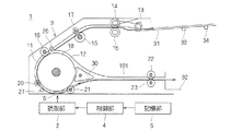
図1は、本発明の一実施形態に係る画像読取装置の構成を示す図である。図1に示すように、本実施形態に係る画像読取装置1は、読取部2、原稿搬送機構3、制御部4、及び記憶部5を備えている。この原稿搬送機構3は、原稿を搬送する過程でスイッチバック反転し、原稿の表裏を反転させる機能を有している。この画像読取装置1が読み取る画像は、白黒画像であってもよいし、カラー画像であってもよい。
FIG. 1 is a diagram illustrating a configuration of an image reading apparatus according to an embodiment of the present invention. As shown in FIG. 1, the
読取部2は、原稿搬送機構3により搬送される原稿の画像を、読取位置6にて読み取る。このような読取部2は、図示しないCCD(Charge Coupled Device)等の撮像素子、及びその撮像素子の受光面上に原稿の画像を結像させる光学系を備えている。
The
原稿搬送機構3は、原稿を搬送するための第1及び第2の搬送路11,12、搬送路11,12に沿って原稿を搬送する複数のローラ13〜23、原稿の位置を検出するための複数のセンサ26,27を備えている。
The
第1の搬送路11は、読み取り前の原稿が載せられる原稿トレイ31と、読み取り後の原稿が排出される排出トレイ32との間を結ぶように設けられている。この第1の搬送路11の途中に読取位置6が設けられる。第2の搬送路12は、第1の搬送路11内で読取位置6を通過した原稿を、第1の搬送路11の読取位置6の搬送方向上流側の部分に戻すためのものである。この第2の搬送路12の入り口部には、原稿を第1の搬送路11から第2の搬送路12に案内するための案内部材30が設けられている。この案内部材30は、原稿を第1の搬送路11から第2の搬送路12に案内するときには図1の実線で示された状態から破線で示される状態へと回転される。第2の搬送路12への原稿の案内が終了したときには、案内部材30は、破線で示される状態から実線で示される状態へと戻される。原稿トレイ31には、原稿の向き、サイズ又は向きとサイズの両方を検出するための少なくとも1つ(図1の図示例では複数)のセンサ33,34が備えられる。
The
ローラ13〜23のうち、ローラ13,14,16,18,22は駆動ローラであり、ローラ15,17,19〜21,23が従動ローラである。センサ26は、原稿の搬送方向下流側の端部がローラ18とローラ19の接触部に到達したことを検出する。搬送されてきた原稿の搬送方向下流側の端部がローラ18とローラ19の接触部に当たるまでは、ローラ18を停止させておき、原稿の搬送方向下流側の端部が前記接触部に当たったことをセンサ19により検出してから、ローラ18を駆動させる。これによって、仮に原稿の向きが搬送方向に対して斜めに傾いていた場合には、原稿の向きが搬送方向と平行に修正される。また、センサ27は、原稿の搬送方向下流側の端部が読取位置6に接近したことを検出する。
Among the
制御部4は、読取部2及び原稿搬送機構3の制御を行う。記憶部5には、制御部4の制御に必要な設定情報等が格納されている。この制御部4の制御内容等については、後に詳述する。
The
次に、原稿の表裏の画像を読み取る際の原稿搬送機構3による原稿の搬送について説明する。この画像搬送機構3では、原稿を搬送する過程で原稿の表裏を反転できる。これによって、単一の読取部2によって原稿の表裏の画像を読み取ることができる。より詳細には、原稿は、最初に読み取れられる第1面が上向きに原稿トレイ31上に配置される。そして、原稿は、図1の矢印付きの実線101で示すように、ローラ13〜15によって原稿トレイ31上から第1の搬送路11内に導入され、ローラ16,17の間を通過してローラ18とローラ19の接触部に到達する。原稿の搬送方向下流側の端部がローラ18とローラ19の接触部に到達したことがセンサ26によって検出され、これに応じて停止されていたローラ18が駆動される。これによって、原稿はローラ18とローラ19,20の間を通過し、読取位置6を経て、ローラ18とローラ21の間を通過する。このとき、原稿は第1面を読取部2側に向けられた状態で読取位置6を通過する。この原稿の通過に伴って読取部2により原稿の第1面の画像が読み取られる。ローラ18とローラ21の間を通過した原稿は、ローラ22,23の間に通される。
Next, document conveyance by the
続いて、原稿の第2面の画像を読み取るために、原稿の表裏の反転が行われる。原稿の搬送方向上流側の端部が案内部材30を通過した時点で、案内部材30が図1の実線で示す状態から破線で示す状態に変化されるとともに、ローラ22,23の回転方向が逆転される。これによって、図2の矢印付きの実線102で示すように、原稿が第1の搬送路11内を逆向きに搬送され、案内部材30によって第1の搬送路11内から第2の搬送路12内に導入される。原稿は、第2の搬送路12を経て第1の搬送路11における読取位置6の搬送方向上流側(ここでは、ローラ18とローラ19の接触部の搬送方向上流側)に導入される。そして、原稿はローラ18とローラ19,20の間を通過し、読取位置6を経て、ローラ18とローラ21の間を通過する。このとき、原稿は第2面を読取部2側に向けられた状態で読取位置6を通過する。この原稿の通過に伴って読取部2により原稿の第2面の画像が読み取られる。ローラ18とローラ21との間を通過した原稿は、ローラ22,23の間に通される。
Subsequently, in order to read the image on the second side of the document, the front and back of the document are reversed. When the end on the upstream side in the document transport direction passes through the
続いて、第2面の読み取り後に原稿の表裏を通常の状態に戻すために、原稿の表裏の反転が行われる。原稿の搬送方向上流側の端部が案内部材30を通過した時点で、案内部材30が図1の実線で示す状態から破線で示す状態に変化されるとともに、ローラ22,23の回転方向が逆転される。これによって、図3の矢印付きの破線103で示すように、原稿が第1の搬送路11内を逆向きに搬送され、案内部材30によって第1の搬送路11内から第2の搬送路12内に導入される。原稿は、第2の搬送路12を経て第1の搬送路11におけるローラ18とローラ19の接触部の搬送方向上流側に導入される。そして、原稿はローラ18とローラ19,20の間を通過し、読取位置6を経て、ローラ18とローラ21の間を通過する。このとき、原稿は第1面を読取部2側に向けられた状態で読取位置6を通過するが、原稿の画像の読み取りは行われない。ローラ18とローラ21との間を通過した原稿は、ローラ22,23の間に通され、排出トレイ32に排出される。
Subsequently, in order to return the front and back of the document to the normal state after reading the second surface, the front and back of the document are reversed. When the end on the upstream side in the document transport direction passes through the
このような画像読取装置1では、原稿の第1面の読み取り時と第2面の読み取り時とで、原稿の搬送経路の相違等に起因し、原稿にかかる負荷(例えば、張力)に差が生じる場合がある。このような負荷の差は、原稿の第1面の読み取り時と第2面の読み取り時とで原稿の搬送方向の伸縮の差を招く。
In such an
そこで、本実施形態に係る画像読取装置1では、制御部4が、読取部2の撮像素子が原稿の画像を読み取るときの原稿の搬送方向についての読取タイミングを規定するクロック周期を、原稿の第1面及び第2面毎に個別に調節する。第1面及び第2面の読み取り時の各クロック周期は、記憶部5に登録されている。制御部4は、第1面及び第2面の各読み取り時にそのクロック周期を記憶部5から読み込み、読取部2の制御に用いる。
Therefore, in the
そして、原稿の第1面の読み取り時と第2面の読み取り時とで原稿にかかる負荷(例えば、張力)に差が生じる場合には、読み取り時のクロック周期が原稿の第1面及び第2面毎に個別に調節される。なお、ローラ18等の原稿を搬送する際の回転速度は、制御の簡単化のため、第1面の読み取り時と第2面の読み取り時とで同一に設定される。
If there is a difference in the load (for example, tension) applied to the original between reading the first side of the original and reading the second side, the clock cycle at the time of reading is the first and second sides of the original. Each face is adjusted individually. It should be noted that the rotation speed when the document such as the
例えば、原稿が原稿トレイ31から第1の搬送路11内に導入されるときには、原稿を1枚ずつ分離する分離部(ローラ13等が設けられる部分)で原稿に大きな負荷がかかりやすい。このため、第1面の読み取り時の方が第2面の読み取り時よりも原稿に大きな負荷がかかり、原稿が搬送方法に延びる場合がある。このような場合には、読取部2の搬送方向についてのクロック周期が、第1面の読み取り時の方が第2面の読み取り時よりも大きくなるように設定される。これによって、第1面の読取画像と第2面の読取画像との間に搬送方向に伸縮の差が生じるのが回避される。なお、ここでは第1面の読み取り時の方が第2面の読み取り時よりも原稿に大きな負荷がかかる場合について説明したが、これは一例に過ぎず、装置1の構成により、第2面の読み取り時の方が第1面の読み取り時よりも原稿に大きな負荷がかかる場合もある。また、第1及び第2の搬送路11,12及びローラ13〜23等の構成についても上記に例は一例に過ぎず、任意の構成を採用できる。
For example, when a document is introduced from the
また、第1面及び第2面の各読み取り時に用いられるクロック周期は、画像読取装置1が工場から出荷されるときなどに、図示しない操作部又はデータ読込部等から作業者によって入力され、記憶部5に記憶される。
Further, the clock cycle used at the time of reading each of the first surface and the second surface is inputted and stored by an operator from an operation unit or a data reading unit (not shown) when the
以上のように、本実施形態によれば、原稿の第1面の読み取り時と第2面の読み取り時とで原稿にかかる負荷(例えば、張力)に差が生じる場合には、読み取り時のクロック周期を原稿の第1面及び第2面毎に個別に調節できる。その結果、第1面の読取画像と第2面の読取画像との間に搬送方向に伸縮の差が生じるのを回避できる。 As described above, according to the present embodiment, when there is a difference in load (for example, tension) applied to the document between reading the first side of the document and reading the second side, the clock at the time of reading is read. The period can be individually adjusted for each of the first and second sides of the document. As a result, it is possible to avoid a difference in expansion and contraction in the transport direction between the read image on the first surface and the read image on the second surface.
また、読取部2を2つ設ける必要がないため、低コスト化に有利である。
In addition, since it is not necessary to provide two
また、原稿を搬送するローラ18等の回転速度が、第1面の読み取り時と第2面の読み取り時とで同一にされているため、原稿搬送機構3の制御が簡単になる。
In addition, since the rotation speed of the
以下では、上述の実施形態の変形例について説明する。 Below, the modification of the above-mentioned embodiment is demonstrated.
上述の実施形態では、原稿の第1面又は第2面の搬送方向の全長に渡って同一のクロック周期で画像の読み取りが行われるようになっている。この点に関する変形例として、制御部4が、原稿の第1面又は第2面内において読取部2のクロック周期を、原稿の原稿搬送機構3の搬送路11,12内における位置に応じて変化させてもよい。例えば、原稿にかかる負荷は、原稿の搬送路11,12内におけるローラ13〜23同士の接触部の通過状況に応じて変化する場合がある。このような場合には、例えば、原稿の搬送方向下流側の端部が搬送路11,12内におけるローラ13〜23同士の接触部を通過するタイミングに応じて、読取部2のクロック周期を変化させる。これによって、原稿の第1面又は第2面の読み取っている途中で原稿にかかる負荷が変化した場合にも、原稿の読取画像に搬送方向について伸縮に差が生じるのを回避できる。
In the above-described embodiment, the image is read at the same clock cycle over the entire length of the first surface or the second surface of the document in the conveyance direction. As a modified example regarding this point, the
なお、このクロック周期の調節は、第1面の読み取り時と第2面の読み取り時とで個別に行われる。また、原稿(例えば、原稿の搬送方向上流側の端部)の搬送路11,12内における位置情報の取得には、例えば、センサ33,34,26,27等により得られる原稿のサイズ、向き及び位置情報が用いられる。また、読取部2により得られる原稿の搬送方向下流側の端部が読取位置6を通過した時刻データ等も用いられる。
Note that the adjustment of the clock cycle is performed separately for reading the first surface and reading the second surface. In addition, for obtaining position information of the original (for example, an upstream end in the original conveyance direction) in the
また、原稿搬送機構3のローラ13〜23は、長年の使用による摩耗等により、ローラ13〜23の径等に変化が生じる場合がある。このようにローラ13〜23の径等が変化した場合には、ローラ13〜23が原稿を搬送する際に原稿にかかる負荷も変化する。
In addition, the
そこで、上述の実施形態に対するさらなる変形例として、制御部4が、読取部2が原稿を読み取る際のクロック周期を、画像読取装置1の使用度合い(例えば、原稿の読み取り回数の増加、又は画像読取装置1の使用期間の進展等)に応じて変化させてもよい。
Therefore, as a further modification to the above-described embodiment, the
1 画像読取装置
2 読取部
3 原稿搬送機構
4 制御部
5 記憶部
11 第1の搬送路
12 第2の搬送路
13〜23 ローラ
DESCRIPTION OF
Claims (2)
前記原稿の第1面を前記読取部側に向けて前記原稿を前記読取部に供給した後、前記原稿の第2面を前記読取部側に向けて前記原稿を前記読取部に供給する原稿搬送機構と、
前記読取部が前記原稿の画像を読み取るときの原稿の搬送方向についての読取タイミングを規定するクロック周期を、前記原稿の前記第1面の読み取り時のクロック周期が前記第2面の読み取り時のクロック周期よりも大きくなるように設定する制御部と、を備え、
前記原稿搬送機構は、前記原稿を搬送するための第1及び第2の搬送路と、読み取り前の前記原稿が載せられる原稿トレイから前記原稿を1枚ずつ分離する分離部と、前記原稿を前記第1の搬送路及び前記第2の搬送路に沿って搬送する少なくとも1つのローラとを備え、
前記第1の搬送路は、前記原稿トレイと読み取り後の前記原稿が排出される排出トレイとの間を、前記読取部による読み取りが行われる読取位置を経て結ぶように設けられ、
前記第2の搬送路は、前記原稿の前記第2面の読み取り時に、前記第1の搬送路に沿って搬送される前記原稿を、前記第1の搬送路上の前記読取位置の搬送方向下流側の部分から、前記原稿の前記搬送方向に対する向きを反転させて前記読取位置の搬送方向上流側の部分に戻すように設けられ、
前記ローラの前記第1面を前記読取部側に向けて前記原稿を搬送するときの回転速度と、前記第2面を前記読取部側に向けて前記原稿を搬送するときの回転速度とが一致されることを特徴とする画像読取装置。 A reading unit for reading an image of a conveyed document;
Document transport for supplying the document to the reading unit with the first surface of the document facing the reading unit and supplying the document to the reading unit, and then feeding the second surface of the document to the reading unit Mechanism,
A clock cycle that defines a reading timing in the document transport direction when the reading unit reads the image of the document, and a clock cycle when reading the first surface of the document is a clock when reading the second surface. A control unit that is set to be larger than the cycle ,
The document transport mechanism includes first and second transport paths for transporting the document, a separation unit that separates the documents one by one from a document tray on which the document before reading is placed, and the document and at least one roller is conveyed along the first conveying path and the second conveying path of,
The first conveyance path is provided so as to connect the document tray and a discharge tray from which the document after reading is discharged via a reading position where reading by the reading unit is performed,
The second transport path is a downstream side in the transport direction of the reading position on the first transport path for transporting the document transported along the first transport path when reading the second surface of the document. Is provided so as to reverse the direction of the document with respect to the conveyance direction and to return to the upstream side of the reading position in the conveyance direction,
The rotational speed when the original is transported with the first surface of the roller facing the reading unit side coincides with the rotational speed when the original is transported with the second surface facing the reading unit. An image reading apparatus.
前記制御部は、前記原稿の前記原稿搬送機構の搬送路内における位置に応じて前記クロック周期を変化させることを特徴とする画像読取装置。 The image reading apparatus according to claim 1,
The image reading apparatus, wherein the control unit changes the clock cycle according to a position of the document in a transport path of the document transport mechanism.
Priority Applications (1)
| Application Number | Priority Date | Filing Date | Title |
|---|---|---|---|
| JP2007183659A JP5115901B2 (en) | 2007-07-12 | 2007-07-12 | Image reading device |
Applications Claiming Priority (1)
| Application Number | Priority Date | Filing Date | Title |
|---|---|---|---|
| JP2007183659A JP5115901B2 (en) | 2007-07-12 | 2007-07-12 | Image reading device |
Publications (2)
| Publication Number | Publication Date |
|---|---|
| JP2009021882A JP2009021882A (en) | 2009-01-29 |
| JP5115901B2 true JP5115901B2 (en) | 2013-01-09 |
Family
ID=40361098
Family Applications (1)
| Application Number | Title | Priority Date | Filing Date |
|---|---|---|---|
| JP2007183659A Expired - Fee Related JP5115901B2 (en) | 2007-07-12 | 2007-07-12 | Image reading device |
Country Status (1)
| Country | Link |
|---|---|
| JP (1) | JP5115901B2 (en) |
Family Cites Families (9)
| Publication number | Priority date | Publication date | Assignee | Title |
|---|---|---|---|---|
| JPH088628B2 (en) * | 1990-09-27 | 1996-01-29 | 株式会社テック | Image reader |
| JP2000038234A (en) * | 1998-07-23 | 2000-02-08 | Sharp Corp | Document feeder |
| JP2000115459A (en) * | 1998-10-02 | 2000-04-21 | Canon Inc | Image reading device and computer readable storage medium |
| JP4312726B2 (en) * | 2005-02-17 | 2009-08-12 | シャープ株式会社 | Image reading device |
| JP4182072B2 (en) * | 2005-03-02 | 2008-11-19 | キヤノン株式会社 | Image reading apparatus and image expansion / contraction correction method |
| JP4381338B2 (en) * | 2005-03-25 | 2009-12-09 | シャープ株式会社 | Image reading device |
| JP2006270822A (en) * | 2005-03-25 | 2006-10-05 | Sharp Corp | Image reading device |
| JP4500728B2 (en) * | 2005-04-28 | 2010-07-14 | キヤノン株式会社 | Automatic document feeder and image forming apparatus |
| JP4872369B2 (en) * | 2006-02-10 | 2012-02-08 | 富士ゼロックス株式会社 | Image reading device |
-
2007
- 2007-07-12 JP JP2007183659A patent/JP5115901B2/en not_active Expired - Fee Related
Also Published As
| Publication number | Publication date |
|---|---|
| JP2009021882A (en) | 2009-01-29 |
Similar Documents
| Publication | Publication Date | Title |
|---|---|---|
| US8020861B2 (en) | Sheet conveyance device and image forming apparatus | |
| US8149479B2 (en) | Original transport and reading apparatus | |
| JP5132368B2 (en) | Image reading apparatus and image forming apparatus | |
| JP2006335516A (en) | Sheet skew correcting and conveying apparatus and image forming apparatus | |
| JP2009018888A (en) | Medium front/back inverting device | |
| US20130277172A1 (en) | Sheet conveyance device for conveying sheet | |
| JP6425191B2 (en) | Paper conveying apparatus and image forming system | |
| US7637500B2 (en) | Advancing a media sheet along a media path | |
| JP5115901B2 (en) | Image reading device | |
| CN102795495A (en) | Document feeding device and image forming apparatus | |
| US20070075483A1 (en) | Sheet conveying apparatus and image forming apparatus | |
| JP2009292614A (en) | Image forming device | |
| JP5760209B2 (en) | Erasing device and image erasing method | |
| US7444115B2 (en) | Two-side image forming apparatus | |
| US20120076564A1 (en) | Image forming apparatus having preregistration mechanism | |
| JP5460822B2 (en) | Image reading apparatus and image forming apparatus | |
| JP2015061150A (en) | Scanner | |
| JP4337487B2 (en) | Image forming apparatus | |
| JP6176022B2 (en) | scanner | |
| JP2009018886A (en) | Image reading device | |
| JP2009107821A (en) | Image forming apparatus | |
| JP2001122529A (en) | Double-side document reader | |
| JP2010208834A (en) | Double-sided image forming device | |
| JP2005335940A (en) | Sheet-like member carrying device | |
| KR101445212B1 (en) | Document transporting apparatus improved in discharge section and image forming apparatus including the same |
Legal Events
| Date | Code | Title | Description |
|---|---|---|---|
| A621 | Written request for application examination |
Free format text: JAPANESE INTERMEDIATE CODE: A621 Effective date: 20100421 |
|
| A977 | Report on retrieval |
Free format text: JAPANESE INTERMEDIATE CODE: A971007 Effective date: 20110811 |
|
| A131 | Notification of reasons for refusal |
Free format text: JAPANESE INTERMEDIATE CODE: A131 Effective date: 20110830 |
|
| A521 | Request for written amendment filed |
Free format text: JAPANESE INTERMEDIATE CODE: A523 Effective date: 20111024 |
|
| A131 | Notification of reasons for refusal |
Free format text: JAPANESE INTERMEDIATE CODE: A131 Effective date: 20120305 |
|
| A521 | Request for written amendment filed |
Free format text: JAPANESE INTERMEDIATE CODE: A523 Effective date: 20120414 |
|
| TRDD | Decision of grant or rejection written | ||
| A01 | Written decision to grant a patent or to grant a registration (utility model) |
Free format text: JAPANESE INTERMEDIATE CODE: A01 Effective date: 20120924 |
|
| A01 | Written decision to grant a patent or to grant a registration (utility model) |
Free format text: JAPANESE INTERMEDIATE CODE: A01 |
|
| R150 | Certificate of patent or registration of utility model |
Free format text: JAPANESE INTERMEDIATE CODE: R150 Ref document number: 5115901 Country of ref document: JP Free format text: JAPANESE INTERMEDIATE CODE: R150 |
|
| A61 | First payment of annual fees (during grant procedure) |
Free format text: JAPANESE INTERMEDIATE CODE: A61 Effective date: 20121007 |
|
| FPAY | Renewal fee payment (event date is renewal date of database) |
Free format text: PAYMENT UNTIL: 20151026 Year of fee payment: 3 |
|
| R250 | Receipt of annual fees |
Free format text: JAPANESE INTERMEDIATE CODE: R250 |
|
| R250 | Receipt of annual fees |
Free format text: JAPANESE INTERMEDIATE CODE: R250 |
|
| R250 | Receipt of annual fees |
Free format text: JAPANESE INTERMEDIATE CODE: R250 |
|
| R250 | Receipt of annual fees |
Free format text: JAPANESE INTERMEDIATE CODE: R250 |
|
| R250 | Receipt of annual fees |
Free format text: JAPANESE INTERMEDIATE CODE: R250 |
|
| R250 | Receipt of annual fees |
Free format text: JAPANESE INTERMEDIATE CODE: R250 |
|
| LAPS | Cancellation because of no payment of annual fees |