JP5116789B2 - Hydraulic control device for transmission and control method therefor - Google Patents
Hydraulic control device for transmission and control method therefor Download PDFInfo
- Publication number
- JP5116789B2 JP5116789B2 JP2010052373A JP2010052373A JP5116789B2 JP 5116789 B2 JP5116789 B2 JP 5116789B2 JP 2010052373 A JP2010052373 A JP 2010052373A JP 2010052373 A JP2010052373 A JP 2010052373A JP 5116789 B2 JP5116789 B2 JP 5116789B2
- Authority
- JP
- Japan
- Prior art keywords
- oil pump
- electric oil
- air
- transmission
- mixed
- Prior art date
- Legal status (The legal status is an assumption and is not a legal conclusion. Google has not performed a legal analysis and makes no representation as to the accuracy of the status listed.)
- Active
Links
Images



Classifications
-
- F—MECHANICAL ENGINEERING; LIGHTING; HEATING; WEAPONS; BLASTING
- F16—ENGINEERING ELEMENTS AND UNITS; GENERAL MEASURES FOR PRODUCING AND MAINTAINING EFFECTIVE FUNCTIONING OF MACHINES OR INSTALLATIONS; THERMAL INSULATION IN GENERAL
- F16H—GEARING
- F16H61/00—Control functions within control units of change-speed- or reversing-gearings for conveying rotary motion ; Control of exclusively fluid gearing, friction gearing, gearings with endless flexible members or other particular types of gearing
- F16H61/0021—Generation or control of line pressure
- F16H61/0025—Supply of control fluid; Pumps therefor
- F16H61/0031—Supply of control fluid; Pumps therefor using auxiliary pumps, e.g. pump driven by a different power source than the engine
-
- F—MECHANICAL ENGINEERING; LIGHTING; HEATING; WEAPONS; BLASTING
- F16—ENGINEERING ELEMENTS AND UNITS; GENERAL MEASURES FOR PRODUCING AND MAINTAINING EFFECTIVE FUNCTIONING OF MACHINES OR INSTALLATIONS; THERMAL INSULATION IN GENERAL
- F16H—GEARING
- F16H61/00—Control functions within control units of change-speed- or reversing-gearings for conveying rotary motion ; Control of exclusively fluid gearing, friction gearing, gearings with endless flexible members or other particular types of gearing
- F16H2061/004—Venting trapped air from hydraulic systems
-
- F—MECHANICAL ENGINEERING; LIGHTING; HEATING; WEAPONS; BLASTING
- F16—ENGINEERING ELEMENTS AND UNITS; GENERAL MEASURES FOR PRODUCING AND MAINTAINING EFFECTIVE FUNCTIONING OF MACHINES OR INSTALLATIONS; THERMAL INSULATION IN GENERAL
- F16H—GEARING
- F16H2312/00—Driving activities
- F16H2312/14—Going to, or coming from standby operation, e.g. for engine start-stop operation at traffic lights
-
- F—MECHANICAL ENGINEERING; LIGHTING; HEATING; WEAPONS; BLASTING
- F16—ENGINEERING ELEMENTS AND UNITS; GENERAL MEASURES FOR PRODUCING AND MAINTAINING EFFECTIVE FUNCTIONING OF MACHINES OR INSTALLATIONS; THERMAL INSULATION IN GENERAL
- F16H—GEARING
- F16H2312/00—Driving activities
- F16H2312/20—Start-up or shut-down
-
- F—MECHANICAL ENGINEERING; LIGHTING; HEATING; WEAPONS; BLASTING
- F16—ENGINEERING ELEMENTS AND UNITS; GENERAL MEASURES FOR PRODUCING AND MAINTAINING EFFECTIVE FUNCTIONING OF MACHINES OR INSTALLATIONS; THERMAL INSULATION IN GENERAL
- F16H—GEARING
- F16H37/00—Combinations of mechanical gearings, not provided for in groups F16H1/00 - F16H35/00
- F16H37/02—Combinations of mechanical gearings, not provided for in groups F16H1/00 - F16H35/00 comprising essentially only toothed or friction gearings
- F16H37/021—Combinations of mechanical gearings, not provided for in groups F16H1/00 - F16H35/00 comprising essentially only toothed or friction gearings toothed gearing combined with continuously variable friction gearing
- F16H37/022—Combinations of mechanical gearings, not provided for in groups F16H1/00 - F16H35/00 comprising essentially only toothed or friction gearings toothed gearing combined with continuously variable friction gearing the toothed gearing having orbital motion
Landscapes
- Engineering & Computer Science (AREA)
- General Engineering & Computer Science (AREA)
- Mechanical Engineering (AREA)
- Control Of Transmission Device (AREA)
Description
本発明は変速機の油圧制御装置およびその制御方法に関するものである。 The present invention relates to a transmission hydraulic control device and a control method therefor.
エンジンが駆動している場合にオイルを供給可能な機械式オイルポンプと、エンジンを停止している場合にオイルを供給可能とする電動オイルポンプとを備え、例えばアイドルストップ制御を行っている場合には、変速機の摩擦締結要素に電動オイルポンプから油圧を供給する車両が知られている。 Equipped with a mechanical oil pump that can supply oil when the engine is running and an electric oil pump that can supply oil when the engine is stopped, for example when performing idle stop control There is known a vehicle that supplies hydraulic pressure from an electric oil pump to a frictional engagement element of a transmission.
このような車両においては、電動オイルポンプに空気が混入している場合には、電動オイルポンプの油圧の立ち上がりが遅くなってしまう。 In such a vehicle, when air is mixed in the electric oil pump, the rise of the hydraulic pressure of the electric oil pump is delayed.
そのため、アイドルストップ制御をする直前に電動オイルポンプを作動させて、電動オイルポンプに混入した空気を撹拌させて分散化させることで電動オイルポンプの油圧の立ち上がりを向上させるものが特許文献1に開示されている。
For this reason,
上記発明を用いた場合であっても、例えば電動オイルポンプに混入した空気量が多い場合には電動オイルポンプの油圧が所定時間立ち上がらないおそれがある。このような場合にはエンジンを始動させて機械式オイルポンプによって油圧を供給している。 Even when the above-described invention is used, for example, when the amount of air mixed in the electric oil pump is large, the hydraulic pressure of the electric oil pump may not rise for a predetermined time. In such a case, the engine is started and hydraulic pressure is supplied by a mechanical oil pump.
しかし、この場合には、電動オイルポンプには空気が混入したままになるため、次回に電動オイルポンプを始動させた場合には電動オイルポンプの油圧立ち上がりが遅くなる、といった問題点がある。 However, in this case, since the electric oil pump is still mixed with air, there is a problem that when the electric oil pump is started next time, the hydraulic pressure rise of the electric oil pump is delayed.
本発明はこのような問題点を解決するために発明されたもので、電動オイルポンプの油圧立ち上がりを早くすることを目的とする。 The present invention has been invented to solve such problems, and has an object of speeding up the hydraulic pressure rise of an electric oil pump.
本発明のある態様に係る変速機の制御装置は、車両を駆動する動力源により駆動される機械式オイルポンプおよび電気モータによって駆動される電動オイルポンプから供給される油圧を制御し、変速機の摩擦締結要素を締結または開放する変速機の油圧制御装置であって、電動オイルポンプに空気が混入しているかどうか判定する空気混入判定手段と、空気混入判定手段によって電動オイルポンプに空気が混入していると判定され、動力源のイグニッションスイッチがオン状態からオフ状態へ変更された場合に、電動オイルポンプを駆動させて電動オイルポンプに混入した空気をオイルと共に電動オイルポンプから排出する空気排出手段と、を備える。 A transmission control device according to an aspect of the present invention controls a hydraulic pressure supplied from a mechanical oil pump driven by a power source driving a vehicle and an electric oil pump driven by an electric motor, A hydraulic control device for a transmission that engages or disengages a frictional engagement element. Air mixing determination means for determining whether air is mixed in the electric oil pump, and air is mixed in the electric oil pump by the air mixing determination means. It is determined that, when the ignition switch of the power source is changed from the oN state to the oFF state, the air discharge a by driving the electric oil pump mixed the electric oil pump air discharged from both the electric oil pump and an oil Means.
本発明の別の態様に係る変速機の制御装置の制御方法は、車両を駆動する動力源により駆動される機械式オイルポンプおよび電気モータによって駆動される電動オイルポンプから供給される油圧を制御し、変速機の摩擦締結要素を締結または開放する変速機の油圧制御装置の制御方法であって、電動オイルポンプに空気が混入しているかどうか判定し、電動オイルポンプに空気が混入していると判定され、動力源のイグニッションスイッチがオン状態からオフ状態へ変更された場合に、電動オイルポンプを駆動させて電動オイルポンプに混入した空気をオイルと共に電動オイルポンプから排出する。 A control method of a transmission control device according to another aspect of the present invention controls a hydraulic pressure supplied from a mechanical oil pump driven by a power source driving a vehicle and an electric oil pump driven by an electric motor. , A control method of a transmission hydraulic control device for fastening or releasing a frictional engagement element of a transmission, wherein it is determined whether air is mixed in the electric oil pump, and air is mixed in the electric oil pump is determined, the ignition switch of the power source when it is changed from the oN state to the oFF state, the by driving the electric oil pump mixed the electric oil pump air discharged from both the electric oil pump and an oil.
これらの態様によれば、電動オイルポンプに空気が混入した状態でイグニッションスイッチがオフにされた場合に、電動オイルポンプに入った空気を電動オイルポンプから排出することができる。そのため、次回に電動オイルポンプを立ち上げる場合に、電動オイルポンプの油圧立ち上がりを素早く行うことができる。 According to these aspects, when the ignition switch is turned off while air is mixed in the electric oil pump, the air that has entered the electric oil pump can be discharged from the electric oil pump. Therefore, when the electric oil pump is started up next time, the hydraulic pressure of the electric oil pump can be quickly raised.
本発明によると、電動オイルポンプの油圧立ち上がりを早くすることができる。 According to the present invention, the hydraulic oil pressure rise of the electric oil pump can be accelerated.
以下、添付図面を参照しながら本発明の実施形態について説明する。なお、以下の説明において、ある変速機構の「変速比」は、当該変速機構の入力回転速度を当該変速機構の出力回転速度で割って得られる値である。また、「最Low変速比」は当該変速機構の最大変速比、「最High変速比」は当該変速機構の最小変速比である。 Hereinafter, embodiments of the present invention will be described with reference to the accompanying drawings. In the following description, the “transmission ratio” of a transmission mechanism is a value obtained by dividing the input rotational speed of the transmission mechanism by the output rotational speed of the transmission mechanism. The “lowest speed ratio” is the maximum speed ratio of the transmission mechanism, and the “highest speed ratio” is the minimum speed ratio of the transmission mechanism.
図1は本発明の第1実施形態に係る油圧制御装置を搭載した車両の概略構成図である。この車両は動力源としてエンジン1を備える。エンジン1の出力回転は、ロックアップクラッチ付きトルクコンバータ2、第1ギヤ列3、無段変速機(以下、単に「変速機4」という。)、第2ギヤ列5、終減速装置6を介して駆動輪7へと伝達される。第2ギヤ列5には駐車時に変速機4の出力軸を機械的に回転不能にロックするパーキング機構8が設けられている。
FIG. 1 is a schematic configuration diagram of a vehicle equipped with a hydraulic control device according to a first embodiment of the present invention. This vehicle includes an
また、車両には、エンジン1の動力の一部を利用して駆動される機械式オイルポンプ10mと、電動モータによって駆動される電動オイルポンプ10eと、機械式オイルポンプ10mまたは電動オイルポンプ10eからの油圧を調圧して変速機4の各部位に供給する油圧制御回路11と、油圧制御回路11などを制御する変速機コントローラ(油圧制御装置)12とが設けられている。
Further, the vehicle includes a
電動オイルポンプ10eは、バッテリ13から電力が供給されて駆動する電気モータによって駆動し、油圧制御回路11に油圧を供給する。なお、電気モータはモータドライバによって制御されている。機械式オイルポンプ10mによって油圧を供給できない場合、例えばエンジン1が自動停止するアイドルストップ制御を行う場合に、電動オイルポンプ10eは油圧制御回路11に油圧を供給する。電動オイルポンプ10eから吐出されるオイルが流れる流路には、逆止弁14が設けられている。電動オイルポンプ10eと機械式オイルポンプ10mとを比較すると、電動オイルポンプ10eは、機械式オイルポンプ10mよりも小型である。
The
変速機4は、ベルト式無段変速機構(以下、「バリエータ20」という。)と、バリエータ20に直列に設けられる副変速機構30とを備える。「直列に設けられる」とはエンジン1から駆動輪7に至るまでの動力伝達経路においてバリエータ20と副変速機構30が直列に設けられるという意味である。副変速機構30は、この例のようにバリエータ20の出力軸に直接接続されていてもよいし、その他の変速ないし動力伝達機構(例えば、ギヤ列)を介して接続されていてもよい。あるいは、副変速機構30はバリエータ20の前段(入力軸側)に接続されていてもよい。
The
バリエータ20は、プライマリプーリ21と、セカンダリプーリ22と、プーリ21、22の間に掛け回されるVベルト23とを備える。プーリ21、22は、それぞれ固定円錐板と、この固定円錐板に対してシーブ面を対向させた状態で配置され固定円錐板との間にV溝を形成する可動円錐板と、この可動円錐板の背面に設けられて可動円錐板を軸方向に変位させる油圧シリンダ23a、23bとを備える。油圧シリンダ23a、23bに供給される油圧を調整すると、V溝の幅が変化してVベルト23と各プーリ21、22との接触半径が変化し、バリエータ20の変速比が無段階に変化する。
The
副変速機構30は前進2段・後進1段の変速機構である。副変速機構30は、2つの遊星歯車のキャリアを連結したラビニョウ型遊星歯車機構31と、ラビニョウ型遊星歯車機構31を構成する複数の回転要素に接続され、それらの連係状態を変更する複数の摩擦締結要素(Lowブレーキ32、Highクラッチ33、Revブレーキ34)とを備える。各摩擦締結要素32〜34への供給油圧を調整し、各摩擦締結要素32〜34の締結・解放状態を変更すると、副変速機構30の変速段が変更される。
The
例えば、Lowブレーキ32を締結し、Highクラッチ33とRevブレーキ34を解放すれば副変速機構30の変速段は1速となる。Highクラッチ33を締結し、Lowブレーキ32とRevブレーキ34を解放すれば副変速機構30の変速段は1速よりも変速比が小さな2速となる。また、Revブレーキ34を締結し、Lowブレーキ32とHighクラッチ33を解放すれば副変速機構30の変速段は後進となる。なお、以下の説明では、副変速機構30の変速段が1速であるとき「変速機4が低速モードである」と表現し、2速であるとき「変速機4が高速モードである」と表現する。
For example, if the
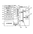
変速機コントローラ12は、図2に示すように、CPU121と、RAM・ROMからなる記憶装置122と、入力インターフェース123と、出力インターフェース124と、これらを相互に接続するバス125とから構成される。
As shown in FIG. 2, the
入力インターフェース123には、アクセルペダルの操作量であるアクセル開度APOを検出するアクセル開度センサ41の出力信号、変速機4の入力回転速度(=プライマリプーリ21の回転速度)を検出する回転速度センサ42の出力信号、車速VSPを検出する車速センサ43の出力信号、油圧制御回路に供給される油圧を検出する油圧センサ44の出力信号、セレクトレバーの位置を検出するインヒビタスイッチ45の出力信号、フットブレーキの踏み込みを検出するブレーキセンサ46の出力信号、車両の始動および停止を切り換えるイグニッションスイッチ47からの出力信号、などが入力される。
The
記憶装置122には、電動オイルポンプ10eを制御する制御プログラム(図3)などが格納されている。CPU121は、記憶装置122に格納されている制御プログラムを読み出して実行し、入力インターフェース123を介して入力される各種信号に対して各種演算処理を施して制御信号を生成し、生成した制御信号を出力インターフェース124を介して油圧制御回路11、電動オイルポンプ10eなどに出力する。CPU121が演算処理で使用する各種値、その演算結果は記憶装置122に適宜格納される。
The
油圧制御回路11は複数の流路、複数の油圧制御弁で構成される。油圧制御回路11は、変速機コントローラ12からの変速制御信号に基づき、複数の油圧制御弁を制御して油圧の供給経路を切り換えるとともに機械式オイルポンプ10m、電動オイルポンプ10eで発生した油圧から必要な油圧を調製し、これを変速機4の各部位に供給する。これにより、バリエータ20の変速比、副変速機構30の変速段が変更され、変速機4の変速が行われる。
The
車両が停車する場合には、燃費を向上させるために、エンジン1を停止させるアイドルストップ制御が行われる。アイドルストップ制御では、副変速機構30のLowブレーキ32のピストンストロークを完了させて、次回の発進に備えている。アイドル制御中は、エンジン1が停止しており、Lowブレーキ32のピストンストロークを完了させるには、電動オイルポンプ10eから油圧を供給する必要がある。
When the vehicle stops, idle stop control for stopping the
しかし、電動オイルポンプ10eに空気が混入すると、電動オイルポンプ10eの油圧の立ち上がりが遅くなってしまう。そこで、本実施形態では、電動オイルポンプ10eに空気が混入した場合には、イグニッションスイッチがOFFにされた場合に電動オイルポンプ10eから空気を排出する。
However, when air is mixed into the
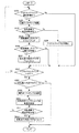
次に電動オイルポンプ10eの空気排出制御について図3のフローチャートを用いて説明する。
Next, air discharge control of the
ステップS100では、アイドルストップ制御中であるかどうか判定する。そして、アイドルストップ制御中である場合には、ステップS101へ進み、アイドルストップ制御中ではない場合には、ステップS106へ進む。 In step S100, it is determined whether the idle stop control is being performed. If the idle stop control is being performed, the process proceeds to step S101. If the idle stop control is not being performed, the process proceeds to step S106.
アイドルストップ制御は、(1)アクセルペダルが踏み込まれていない、(2)ブレーキペダルが踏み込まれている、(3)セレクトレバーがDレンジ、またはNレンジとなっている、(4)車両が停車しているなどの条件を満たしていると開始される。一方、アイドルストップ制御は、(1)アクセルペダルが踏み込まれている、(2)ブレーキペダルが踏み込まれていない、(3)後述する空気混入判定フラグが「1」にセットされている、などの条件を満たすと中止される。アイドルストップ制御が開始されるとエンジン1の回転速度が徐々に低下し、その後エンジン1の回転速度はゼロとなる。なお、アイドルストップ制御を開始するかどうか、またはアイドルストップ制御を中止するかどうかの判定は、ここでは説明しないが他の制御によって行われている。ステップS100では、他の制御の結果に基づいて、アイドルストップ制御中であるかどうか判定している。
In idle stop control, (1) the accelerator pedal is not depressed, (2) the brake pedal is depressed, (3) the select lever is in the D range or N range, (4) the vehicle is stopped. It starts when it meets the conditions such as. On the other hand, the idle stop control includes (1) the accelerator pedal is depressed, (2) the brake pedal is not depressed, and (3) an aeration determination flag to be described later is set to “1”. Canceled if the condition is met. When the idle stop control is started, the rotational speed of the
ステップS101では、油圧センサ44によって油圧制御回路11に供給される油圧が所定油圧以下であるかどうか判定する。
In step S101, it is determined whether or not the hydraulic pressure supplied to the
アイドルストップ制御を開始した場合には、エンジン1の回転速度が徐々に低下し、その後エンジン1は完全に停止し、エンジン1の回転速度はゼロとなる。また、アイドルストップ制御を開始すると、電動オイルポンプ10eが始動する。そのため電動オイルポンプ10eの吐出圧が次第に大きくなる。しかしエンジン1の回転速度がある程度大きい間は機械式オイルポンプ10mの吐出圧が、電動オイルポンプ10eの吐出圧よりも大きく、逆止弁14は閉じており、電動オイルポンプ10eから油圧制御回路11に油圧は供給されない。そして、電動オイルポンプ10eの吐出圧が、機械式オイルポンプ10mの吐出圧よりも大きくなると逆止弁14が開いて電動オイルポンプ10eから油圧が油圧制御回路11に供給される。そのため、油圧センサ44によって検出される油圧は、電動オイルポンプ10eが正常に動作している場合には、電動オイルポンプ10eの吐出圧として設定された所定油圧よりも低くなることはない。
When the idle stop control is started, the rotational speed of the
しかし、電動オイルポンプ10eに空気が混入していると、電動オイルポンプ10eの吐出圧が低くなり、油圧センサ44によって検出される油圧が所定油圧よりも低くなる。
However, if air is mixed in the
そこで、ステップS101では、電動オイルポンプ10eの吐出圧が所定油圧よりも低くなっているかどうか判定することで、電動オイルポンプ10eへの空気の混入を判定する。つまり、所定油圧は、電動オイルポンプ10eに空気が混入している場合に低下する油圧である。そして、電動オイルポンプ10eの吐出圧が所定油圧よりも低い場合にはステップS102へ進み、電動オイルポンプ10eの吐出圧が所定油圧以上である場合にはステップS105へ進む。
Therefore, in step S101, it is determined whether or not the discharge pressure of the
ステップS102では、電動オイルポンプ10eの油圧低下判定タイマをカウントアップする。
In step S102, the oil pressure decrease determination timer of the
ステップS103では、油圧低下判定タイマを第1所定値と比較する。そして油圧低下判定タイマが第1所定値以上である場合にはステップS104へ進み、第1所定値よりも小さい場合にはステップS106へ進む。第1所定値は予め設定される値であり、電動オイルポンプ10eに空気が混入し、電動オイルポンプ10eの吐出圧が低下していると正確に判定できる値である。
In step S103, the oil pressure decrease determination timer is compared with a first predetermined value. If the oil pressure decrease determination timer is greater than or equal to the first predetermined value, the process proceeds to step S104, and if smaller than the first predetermined value, the process proceeds to step S106. The first predetermined value is a value set in advance, and is a value with which it can be accurately determined that air is mixed in the
ステップS104では、空気混入判定フラグを「1」にセットする。これにより、アイドルストップ制御は中止されて、電動オイルポンプ10eは停止する(ステップS103とステップS104とが空気混入判定手段を構成する)。
In step S104, the air mixing determination flag is set to “1”. Thereby, the idle stop control is stopped and the
ステップS101において電動オイルポンプ10eの吐出圧が所定油圧以上である場合には、ステップS105で電動オイルポンプ10eが正常に動作していると判定し、空気混入判定フラグをリセットしてステップS106へ進む。なお空気混入判定フラグはリセットされると「0」になる。
If the discharge pressure of the
ステップS106では、イグニッションスイッチ47がOFFになったかどうか判定する。イグニッションスイッチ47がOFFになった場合にはステップS107へ進み、イグニッションスイッチ47がOFFとなっていない場合にはステップS100へ戻り上記制御を繰り返す。
In step S106, it is determined whether or not the
ステップS107では、空気混入判定フラグが「1」にセットされているかどうか判定する。空気混入判定フラグが「1」にセットされている場合にはステップS108へ進み、空気混入判定フラグが「0」にセットされている場合には本制御を終了する。 In step S107, it is determined whether the air mixing determination flag is set to “1”. When the air mixing determination flag is set to “1”, the process proceeds to step S108, and when the air mixing determination flag is set to “0”, this control is terminated.
ステップS108では、電動オイルポンプ10eを始動させる。空気混入判定フラグが「1」にセットされている場合には、電動オイルポンプ10eに空気が混入しているので、電動オイルポンプ10eを始動させて、電動オイルポンプ10eに混入した空気を電動オイルポンプ10eからオイルと共に排出する。なお、本実施形態では、イグニッションスイッチ47がOFFにされるのとほぼ同時に電動オイルポンプ10eを始動させる(ステップS108が空気排出手段を構成する)。
In step S108, the
ステップS109では、油圧センサ44によって電動オイルポンプ10eの吐出圧を検出する。
In step S109, the
ステップS110では、ステップS109によって検出した油圧が所定油圧以上であるかどうか判定する。ステップS109によって検出した油圧が所定油圧以上であると、電動オイルポンプ10eから空気が混入したオイルが排出されたと判定する。そして、油圧センサ44によって検出された油圧が所定油圧以上の場合にはステップS111へ進み、油圧センサ44によって検出された油圧が所定油圧よりも低い場合にはステップS109へ戻り上記制御を繰り返す。
In step S110, it is determined whether or not the hydraulic pressure detected in step S109 is greater than or equal to a predetermined hydraulic pressure. If the hydraulic pressure detected in step S109 is equal to or higher than the predetermined hydraulic pressure, it is determined that the oil mixed with air is discharged from the
ステップS111では、空気混入判定フラグをリセットする。また、電動オイルポンプ10eが駆動している場合には、電動オイルポンプ10eを停止する。そして本制御を終了する。
In step S111, the air mixing determination flag is reset. Further, when the
なお、本実施形態では、ステップS110によって油圧センサ44によって検出される油圧に基づいて電動オイルポンプ10eから空気が混入したオイルを排出したかどうか判定したが、電動オイルポンプ10eを始動してからの時間に基づいて判定しても良い。この場合、電動オイルポンプ10eにオイルが入っていない状態から電動オイルポンプ10eが完全にオイルで満たされるまでの時間、つまり、空気が混入したオイルが電動オイルポンプ10eから完全に排出されるまでの時間が経過するかどうかによって判定する。
In the present embodiment, it is determined whether the oil mixed with air is discharged from the
次に本実施形態におけるイグニッションスイッチ47(IGN−SW)がOFFにされた場合の電動オイルポンプ10eの駆動状態などを図4のタイムチャートを用いて説明する。
Next, the driving state of the
時間t0において、アイドルストップ条件を満たすと、アイドルストップ制御を開始する。これにより、エンジン1の回転速度が低下し、それに伴い機械式オイルポンプ10mの吐出圧が低下するために油圧センサ44によって検出される油圧が低下する。また、電動オイルポンプ10eが始動する。
If the idle stop condition is satisfied at time t0, the idle stop control is started. As a result, the rotational speed of the
時間t1において、油圧センサ44によって検出した油圧が所定油圧以下となると、油圧低下判定タイマによるカウントアップを開始する。
When the oil pressure detected by the
時間t2において、油圧低下判定タイマが第1所定値となると、電動オイルポンプ10eに空気が混入していると判定し、空気混入判定フラグを「1」にセットする。そして、電動オイルポンプ10eを停止し、アイドルストップ制御を終了する。この場合、電動オイルポンプ10eは、空気が混入した状態で停止する。また、エンジン1を始動し、機械式オイルポンプ10mによって油圧制御回路11に油圧を供給する。
When the oil pressure decrease determination timer reaches the first predetermined value at time t2, it is determined that air is mixed in the
時間t3において、イグニッションスイッチ47がOFFになると、エンジン1の回転速度が低下する。また、電動オイルポンプ10eを始動する。機械式オイルポンプ10mの吐出圧よりも電動オイルポンプ10eの吐出圧が大きくなると、電動オイルポンプ10eから空気がオイルと共に排出される。
When the
時間t4において、電動オイルポンプ10eから空気の排出が完了し、油圧センサ44によって検出される油圧が所定油圧以上となると、電動オイルポンプ10eを停止する。
At time t4, when the discharge of air from the
本発明の第1実施形態の効果について説明する。 The effect of 1st Embodiment of this invention is demonstrated.
例えばアイドルストップ制御を行っている場合に、電動オイルポンプ10eに空気が混入し、油圧制御回路11に十分に油圧を供給できない場合には、アイドルストップ制御を終了し、機械式オイルポンプ10mを駆動させることで油圧制御回路11に油圧を供給し、摩擦締結要素を所定の締結状態とする。しかし、この場合電動オイルポンプ10eには空気が混入したままになっており、次回に電動オイルポンプ10eによって油圧制御回路11に油圧を供給する際に、電動オイルポンプ10eの油圧立ち上がりが悪くなる。
For example, when idling stop control is performed, if air is mixed into the
本実施形態では、電動オイルポンプ10eに空気が混入している場合には、イグニッションスイッチ47がOFFとされた後に、電動オイルポンプ10eを始動させることで、電動オイルポンプ10eに混入した空気をオイルと共に電動オイルポンプ10eから排出する。これにより、次回電動オイルポンプ10eを始動させる場合に、電動オイルポンプ10eの油圧立ち上がり性を向上することができる(請求項1に対応)。
In the present embodiment, when air is mixed in the
エンジン1が自動停止するアイドルストップ制御中に、電動オイルポンプ10eに空気が混入しているかどうか判定することで、イグニッションスイッチ47がOFFとなる毎に電動オイルポンプ10eを始動させることなく電動オイルポンプ10eに空気が混入しているかどうか判定することができる。そのため、電動オイルポンプ10eで消費される電力を少なくすることができる(請求項2に対応)。
During the idle stop control in which the
イグニッションスイッチ47がOFFとされるとほぼ同時に電動オイルポンプ10eの始動を開始するので、電動オイルポンプ10eから空気を素早く排出することができる(請求項3に対応)。
Since the
次に本発明の第2実施形態について説明する。 Next, a second embodiment of the present invention will be described.
第2実施形態については第1実施形態と異なる部分を説明する。 The second embodiment will be described with respect to differences from the first embodiment.
本実施形態は、イグニッションスイッチ47がOFFとされる場合の電動オイルポンプ10eの作動が第1実施形態と異なっている。次に本実施形態の電動オイルポンプ10eの空気排出制御について図5のフローチャートを用いて説明する。
This embodiment differs from the first embodiment in the operation of the
ステップS200からS207までの制御は、第1実施形態と同じ制御であり、ここでの説明は省略する。 The control from step S200 to S207 is the same control as in the first embodiment, and a description thereof is omitted here.
ステップS208では、油圧センサ44によって機械式オイルポンプ10mの吐出圧を検出する。
In step S208, the
ステップS209では、油圧センサ44によって検出される油圧が所定油圧以下である場合にはステップS210へ進み、油圧センサ44によって検出される油圧が所定油圧よりも大きい場合にはステップS208へ戻り上記制御を繰り返す。
In step S209, if the oil pressure detected by the
ステップS210では、電動オイルポンプ10e始動する。機械式オイルポンプ10mの吐出圧が所定油圧よりも大きい場合には、逆止弁14が開かないので電動オイルポンプ10eを始動させても電動オイルポンプ10eからオイルを吐出させることができない。そのため、ステップS209、S210によって機械式オイルポンプ10mの吐出圧が所定油圧以下となってから電動オイルポンプ10eを始動させる。
In step S210, the
ステップS211からS213は第1実施形態のステップS109からS111と同じ制御なので、ここで説明は省略する。 Since steps S211 to S213 are the same control as steps S109 to S111 of the first embodiment, the description thereof is omitted here.
なお、本実施形態では、機械式オイルポンプ10mの吐出圧が所定油圧以下となった場合に電動オイルポンプ10eを始動させたが、イグニッションスイッチ47がOFFになってから、所定時間が経過した後に電動オイルポンプ10eを始動させても良い。所定時間は予め設定される時間であり、電動オイルポンプ10eの吐出圧が、機械式オイルポンプ10mからの吐出圧よりも大きくなったと判定できる時間である。
In the present embodiment, the
本発明の第2実施形態の効果について説明する。 The effect of 2nd Embodiment of this invention is demonstrated.
また、機械式オイルポンプ10mの吐出圧が電動オイルポンプ10eの吐出圧よりも小さくなる場合に、電動オイルポンプ10eを始動させるので、電動オイルポンプ10eからの空気排出を正確に行うことができる(請求項4に対応)。
Moreover, since the
機械式オイルポンプ10mの吐出圧が所定油圧以下なった後に、電動オイルポンプ10eを始動する。つまり、機械式オイルポンプ10mの吐出圧が電動オイルポンプ10eの吐出圧よりも大きく、電動オイルポンプ10eからオイルを排出できない間は、電動オイルポンプ10eを駆動させない。これにより、電動オイルポンプ10eで消費される電力を少なくすることができる。
The
次に本発明の第3実施形態について説明する。 Next, a third embodiment of the present invention will be described.
本実施形態の車両の概略構成図を図6に示す。本実施形態の車両は、電動オイルポンプ10eの回転速度を検出する回転速度センサ48を備える。
FIG. 6 shows a schematic configuration diagram of the vehicle according to the present embodiment. The vehicle of this embodiment includes a
次に本実施形態の電動オイルポンプ10eの空気排出制御について図7のフローチャートを用いて説明する。
Next, air discharge control of the
ステップS300では、アイドルストップ制御を行う準備に入ったかどうか判定する。そして、アイドルストップ制御を行う準備に入ったと判定された場合にはステップS301へ進み、アイドルストップ制御を行う準備に入っていないと判定された場合にはステップS307へ進む。 In step S300, it is determined whether or not preparation for performing idle stop control has been started. If it is determined that preparations for performing idle stop control have been entered, the process proceeds to step S301. If it is determined that preparations for performing idle stop control have not been entered, the process proceeds to step S307.
アイドルストップ制御を行う準備に入ったかどうかは、(1)アクセルペダルが踏み込まれていない、(2)ブレーキペダルが踏み込まれている、(3)セレクトレバーがDレンジ、またはNレンジとなっている、(4)車速が所定車速以下となっているなどの条件を満たす場合にアイドルストップ制御を行う準備に入ったと判定する。 Whether it is ready to perform idle stop control, (1) the accelerator pedal is not depressed, (2) the brake pedal is depressed, (3) the select lever is in the D range or N range (4) When the condition that the vehicle speed is equal to or lower than the predetermined vehicle speed is satisfied, it is determined that preparation for performing the idle stop control has been started.
ステップS301では、電動オイルポンプ10eを始動する。
In step S301, the
ステップS302では、回転速度センサ48によって電動オイルポンプ10eの回転速度を検出し、電動オイルポンプ10eの回転速度が所定回転速度以上であるかどうか判定する。そして、電動オイルポンプ10eの回転速度が所定回転速度以上である場合にはステップS303へ進み、電動オイルポンプ10eの回転速度が所定回転速度よりも小さい場合にはステップS306へ進む。所定回転速度は予め設定された速度であり、電動オイルポンプ10eに空気が混入している場合に上昇する回転速度である。
In step S302, the
アイドルストップ制御を行う前に電動オイルポンプ10eを始動させた場合に、電動オイルポンプ10eに空気が混入していると、電動オイルポンプ10eの駆動抵抗が小さくなるので、電動オイルポンプ10eの回転速度は空気が混入していない場合と比較して大きくなる。
When the
そこで、電動オイルポンプ10eの回転速度が所定回転速度以上である場合には、電動オイルポンプ10eに空気が混入していると判定する。
Therefore, when the rotation speed of the
ステップS303では、電動オイルポンプ10eの回転速度上昇タイマをカウントアップする。
In step S303, the rotation speed increase timer of the
ステップS304では、電動オイルポンプ10eの回転速度上昇タイマが第2所定値以上であるかどうか判定する。そして、電動オイルポンプ10eの回転速度上昇タイマが第2所定値以上である場合にはステップS305へ進み、電動オイルポンプ10eの回転速度上昇タイマが第2所定値よりも小さい場合にはステップS306へ進む。第2所定値は、予め設定された値であり、電動オイルポンプ10eに空気が混入していると正確に判定することができる値である。
In step S304, it is determined whether the rotation speed increase timer of the
ステップS305では空気混入判定フラグを「1」にセットし、アイドルストップ制御を禁止する。また、電動オイルポンプ10eを停止する。
In step S305, the air mixing determination flag is set to “1”, and the idle stop control is prohibited. Further, the
ステップS302において電動オイルポンプ10eの回転速度が所定回転速度よりも小さいと判定されると、ステップS306においてアイドルストップ制御を開始する。また、空気混入判定フラグがリセットされる。
If it is determined in step S302 that the rotational speed of the
ステップS307では、イグニッションスイッチ47がOFFになったかどうか判定する。イグニッションスイッチ47がOFFになった場合にはステップS308へ進み、イグニッションスイッチ47がOFFとなっていない場合にはステップS300へ戻り上記制御を繰り返す。
In step S307, it is determined whether or not the
ステップS308では、空気混入判定フラグが「1」にセットされているかどうか判定する。空気混入判定フラグが「1」にセットされている場合にはステップS309へ進み、空気混入判定フラグが「0」にセットされている場合には本制御を終了する。 In step S308, it is determined whether the air mixing determination flag is set to “1”. When the air mixing determination flag is set to “1”, the process proceeds to step S309, and when the air mixing determination flag is set to “0”, this control is terminated.
ステップS309では電動オイルポンプ10eを始動させる。
In step S309, the
ステップS310では、回転速度センサ48によって電動オイルポンプ10eの回転速度を検出する。
In step S310, the
ステップS311では、電動オイルポンプ10eの回転速度が所定回転速度以下となったかどうか判定する。そして、電動オイルポンプ10eの回転速度が所定回転速度以下となるとステップS312へ進み、電動オイルポンプ10eの回転速度が所定回転速度よりも大きい場合にはステップS310へ戻り上記制御を繰り返す。
In step S311, it is determined whether or not the rotational speed of the
ステップS312では、空気混入判定フラグをリセットする。また、電動オイルポンプ10eが駆動している場合には、電動オイルポンプ10eを停止する。そして本制御を終了する。
In step S312, the air mixing determination flag is reset. Further, when the
なお、本実施形態では、電動オイルポンプ10eの回転速度を検出したが、電動オイルポンプ10eに流れる電流を検出しても良い。この場合、電動オイルポンプ10eに空気が混入していると電動オイルポンプ10eはほぼ無負荷状態で回転することになり、電流が小さくなる。これを検出することで、電動オイルポンプ10eに空気が混入したことを検出しても良い。
In the present embodiment, the rotational speed of the
また、本実施形態では、アイドルストップ制御の準備中である場合にのみ電動オイルポンプ10eを始動させて電動オイルポンプ10eに空気が混入しているかどうか判定したが、これに限られることはない。例えば、アイドルストップ制御中に電動オイルポンプ10eを始動させて電動オイルポンプ10eに空気が混入しているかどうか判定しても良い。これにより、例えばアイドルストップ制御が開始され、機械式オイルポンプ10mからの吐出圧が電動オイルポンプ10eの吐出圧よりも小さくなる前にイグニッションスイッチ47がOFFにされた場合でも、電動オイルポンプ10eに空気が混入しているかどうか判定することができ、電動オイルポンプ10eに混入した空気を確実に排出することができる。
In the present embodiment, the
本発明の第3実施形態の効果について説明する。 The effect of the third embodiment of the present invention will be described.
回転速度センサ48によって電動オイルポンプ10eの回転速度を検出し、電動オイルポンプ10eの回転速度に基づいて電動オイルポンプ10eに空気が混入しているかどうか判定する。これにより、電動オイルポンプ10eからの吐出圧が機械式オイルポンプ10mからの吐出圧よりも小さい場合でも、電動オイルポンプ10eに空気が混入していることを判定することができる。
The
本発明は上記した実施形態に限定されるものではなく、その技術的思想の範囲内でなしうるさまざまな変更、改良が含まれることは言うまでもない。 It goes without saying that the present invention is not limited to the above-described embodiments, and includes various modifications and improvements that can be made within the scope of the technical idea.
1 エンジン(動力源)
10e 電動オイルポンプ
10m 機械式オイルポンプ
11 油圧制御回路
12 変速機コントローラ(油圧制御装置)
30 副変速機
44 油圧センサ
47 イグニッションスイッチ
1 Engine (Power source)
10e
30 Sub-transmission 44
Claims (5)
前記電動オイルポンプに空気が混入しているかどうか判定する空気混入判定手段と、
前記空気混入判定手段によって前記電動オイルポンプに空気が混入していると判定され、前記動力源のイグニッションスイッチがオン状態からオフ状態へ変更された場合に、前記電動オイルポンプを駆動させて前記電動オイルポンプに混入した前記空気をオイルと共に前記電動オイルポンプから排出する空気排出手段と、を備えることを特徴とする変速機の油圧制御装置。 A hydraulic control device for a transmission that controls hydraulic pressure supplied from a mechanical oil pump driven by a power source that drives the vehicle and an electric oil pump driven by an electric motor, and that engages or releases a frictional engagement element of the transmission Because
An air mixing determination means for determining whether air is mixed in the electric oil pump;
When it is determined by the air mixing determination means that air is mixed in the electric oil pump, and the ignition switch of the power source is changed from an on state to an off state, the electric oil pump is driven to drive the electric oil pump. hydraulic control device for a transmission, characterized in that it comprises an air discharge means for discharging the air mixed into the oil pump both from the electric oil pump and an oil, the.
前記電動オイルポンプに空気が混入しているかどうか判定し、
前記電動オイルポンプに空気が混入していると判定され、前記動力源のイグニッションスイッチがオン状態からオフ状態へ変更された場合に、前記電動オイルポンプを駆動させて前記電動オイルポンプに混入した前記空気をオイルと共に前記電動オイルポンプから排出することを特徴とする変速機の油圧制御装置の制御方法。 A hydraulic control device for a transmission that controls hydraulic pressure supplied from a mechanical oil pump driven by a power source that drives the vehicle and an electric oil pump driven by an electric motor, and that engages or releases a frictional engagement element of the transmission Control method,
Determine whether air is mixed in the electric oil pump,
When it is determined that air is mixed in the electric oil pump, and the ignition switch of the power source is changed from an on state to an off state, the electric oil pump is driven and mixed into the electric oil pump. control method of a hydraulic control device for a transmission, characterized in that for discharging air both from the electric oil pump and an oil.
Priority Applications (5)
| Application Number | Priority Date | Filing Date | Title |
|---|---|---|---|
| JP2010052373A JP5116789B2 (en) | 2010-03-09 | 2010-03-09 | Hydraulic control device for transmission and control method therefor |
| US13/019,673 US8433484B2 (en) | 2010-03-09 | 2011-02-02 | Oil pressure control device for transmission and control method thereof |
| EP11001006A EP2369202B1 (en) | 2010-03-09 | 2011-02-08 | Oil pressure control device for transmission and control method thereof |
| CN201110041897.9A CN102192311B (en) | 2010-03-09 | 2011-02-22 | Oil pressure control device for transmission and control method thereof |
| KR1020110020209A KR101778805B1 (en) | 2010-03-09 | 2011-03-08 | Hydraulic pressure control apparatus of transmission and control method for the same |
Applications Claiming Priority (1)
| Application Number | Priority Date | Filing Date | Title |
|---|---|---|---|
| JP2010052373A JP5116789B2 (en) | 2010-03-09 | 2010-03-09 | Hydraulic control device for transmission and control method therefor |
Publications (2)
| Publication Number | Publication Date |
|---|---|
| JP2011185378A JP2011185378A (en) | 2011-09-22 |
| JP5116789B2 true JP5116789B2 (en) | 2013-01-09 |
Family
ID=43919924
Family Applications (1)
| Application Number | Title | Priority Date | Filing Date |
|---|---|---|---|
| JP2010052373A Active JP5116789B2 (en) | 2010-03-09 | 2010-03-09 | Hydraulic control device for transmission and control method therefor |
Country Status (5)
| Country | Link |
|---|---|
| US (1) | US8433484B2 (en) |
| EP (1) | EP2369202B1 (en) |
| JP (1) | JP5116789B2 (en) |
| KR (1) | KR101778805B1 (en) |
| CN (1) | CN102192311B (en) |
Families Citing this family (22)
| Publication number | Priority date | Publication date | Assignee | Title |
|---|---|---|---|---|
| US8833335B2 (en) * | 2011-02-15 | 2014-09-16 | Toyota Jidosha Kabushiki Kaisha | Control device of vehicle oil supply device |
| CN102691650B (en) * | 2011-03-22 | 2015-07-01 | 日立汽车系统株式会社 | Apparatus and method for controlling electric oil pump |
| JP5607010B2 (en) * | 2011-09-21 | 2014-10-15 | 日立オートモティブシステムズ株式会社 | Oil pump system for vehicles |
| JP5961987B2 (en) * | 2011-12-01 | 2016-08-03 | 日産自動車株式会社 | Electric pump discharge flow rate control device |
| JP5769025B2 (en) * | 2011-12-19 | 2015-08-26 | ジヤトコ株式会社 | Vehicle line pressure control device |
| JP2013129390A (en) * | 2011-12-22 | 2013-07-04 | Toyota Motor Corp | Vehicle control system |
| JP5824737B2 (en) | 2012-01-24 | 2015-11-25 | ジヤトコ株式会社 | Hybrid vehicle engine start control device |
| EP2977283B1 (en) * | 2013-03-21 | 2022-09-07 | Nissan Motor Co., Ltd. | Hybrid vehicle |
| WO2014156337A1 (en) * | 2013-03-25 | 2014-10-02 | 本田技研工業株式会社 | Control device for vehicle |
| KR101510331B1 (en) * | 2013-04-01 | 2015-04-07 | 현대자동차 주식회사 | Pump motor control system for automatic transmission and method thereof |
| DE112014003376T5 (en) * | 2013-09-30 | 2016-04-07 | Aisin Aw Co., Ltd. | Control device for a vehicle hydraulic pressure supply device |
| JP5967053B2 (en) | 2013-10-28 | 2016-08-10 | トヨタ自動車株式会社 | Hydraulic control device |
| EP3115650A4 (en) * | 2014-03-04 | 2017-03-01 | Jatco Ltd | Vehicle control device and method for controlling same |
| CN104019222A (en) * | 2014-06-12 | 2014-09-03 | 盛瑞传动股份有限公司 | Automatic speed changer control system |
| DE102015006609B3 (en) | 2015-05-21 | 2016-05-04 | Audi Ag | Method for operating an electrically controllable feed pump in a hydraulic circuit |
| JP6700117B2 (en) * | 2016-06-23 | 2020-05-27 | ジヤトコ株式会社 | Vehicle control device |
| CN108426025B (en) * | 2018-03-12 | 2019-12-03 | 安徽江淮汽车集团股份有限公司 | Double-clutch automatic gearbox method of controlling exhaust gas and control system |
| DE102018130700B4 (en) * | 2018-12-03 | 2020-07-02 | Schaeffler Technologies AG & Co. KG | Method for establishing a hydraulic readiness of a hydraulic system and hydraulic system |
| JP7176540B2 (en) * | 2020-01-16 | 2022-11-22 | トヨタ自動車株式会社 | hydraulic supply system |
| KR102737458B1 (en) * | 2020-07-16 | 2024-12-05 | 섀플러 테크놀로지스 아게 운트 코. 카게 | Method for controlling electrically operated pumps for hydraulic systems |
| CN116964336A (en) * | 2021-01-14 | 2023-10-27 | 加特可株式会社 | Hydraulic control device, hydraulic control method and procedure for hydraulic working machinery |
| US12044308B2 (en) * | 2021-03-05 | 2024-07-23 | Jatco Ltd | Control device for vehicle, control method for vehicle, and non-transitory computer-readable medium |
Family Cites Families (11)
| Publication number | Priority date | Publication date | Assignee | Title |
|---|---|---|---|---|
| JP4576713B2 (en) | 2000-12-28 | 2010-11-10 | アイシン・エィ・ダブリュ株式会社 | Oil pump drive control device |
| JP2003172444A (en) | 2001-12-07 | 2003-06-20 | Aisin Aw Co Ltd | Vehicle drive control device |
| JP2005098468A (en) * | 2003-09-26 | 2005-04-14 | Koyo Seiko Co Ltd | Driving method of in-vehicle electric motor |
| JP3921220B2 (en) * | 2004-12-02 | 2007-05-30 | 本田技研工業株式会社 | Hydraulic supply device |
| JP2006283809A (en) * | 2005-03-31 | 2006-10-19 | Jatco Ltd | Automatic transmission |
| JP4618146B2 (en) * | 2006-01-31 | 2011-01-26 | トヨタ自動車株式会社 | Control device for automatic transmission for vehicle |
| JP2008039030A (en) * | 2006-08-04 | 2008-02-21 | Toyota Motor Corp | Vehicle control device |
| JP4475286B2 (en) | 2007-04-02 | 2010-06-09 | トヨタ自動車株式会社 | Vehicle oil pump control device |
| US8187147B2 (en) * | 2008-03-27 | 2012-05-29 | GM Global Technology Operations LLC | Hydraulic control system for multi-mode hybrid transmission and method of regulating the same |
| JP2009264545A (en) | 2008-04-28 | 2009-11-12 | Aisin Aw Co Ltd | Vehicle control apparatus |
| JP2010052373A (en) | 2008-08-29 | 2010-03-11 | Canon Finetech Inc | Recording apparatus |
-
2010
- 2010-03-09 JP JP2010052373A patent/JP5116789B2/en active Active
-
2011
- 2011-02-02 US US13/019,673 patent/US8433484B2/en active Active
- 2011-02-08 EP EP11001006A patent/EP2369202B1/en not_active Not-in-force
- 2011-02-22 CN CN201110041897.9A patent/CN102192311B/en active Active
- 2011-03-08 KR KR1020110020209A patent/KR101778805B1/en not_active Expired - Fee Related
Also Published As
| Publication number | Publication date |
|---|---|
| KR101778805B1 (en) | 2017-09-14 |
| CN102192311A (en) | 2011-09-21 |
| KR20110102207A (en) | 2011-09-16 |
| US8433484B2 (en) | 2013-04-30 |
| CN102192311B (en) | 2015-05-06 |
| JP2011185378A (en) | 2011-09-22 |
| EP2369202A1 (en) | 2011-09-28 |
| US20110224879A1 (en) | 2011-09-15 |
| EP2369202B1 (en) | 2013-01-23 |
Similar Documents
| Publication | Publication Date | Title |
|---|---|---|
| JP5116789B2 (en) | Hydraulic control device for transmission and control method therefor | |
| EP2426377B1 (en) | Engine auto-stop vehicle and control method therefor | |
| CN102563040B (en) | Coast stop vehicle | |
| JP5315454B2 (en) | Automatic transmission and hydraulic control method thereof | |
| EP2752572B1 (en) | Coast stop vehicle | |
| KR101456755B1 (en) | Coast stop vehicle and control method for the same | |
| EP2428703A2 (en) | Hydraulic control device, control method of thereof and automatic transmission | |
| EP2824367B1 (en) | Control device for transmission mechanism | |
| US9421978B2 (en) | Continuously variable transmission and control method therefor | |
| JP6039094B2 (en) | Control device for stepped transmission mechanism | |
| CN104364131B (en) | Controller of vehicle and control method for vehicle | |
| CN107949730B (en) | Vehicle control device and vehicle control method | |
| WO2014148235A1 (en) | Vehicle control device and vehicle control method | |
| JP6546817B2 (en) | Pump system and control method of pump system | |
| WO2016047215A1 (en) | Vehicle control device and control method therefor |
Legal Events
| Date | Code | Title | Description |
|---|---|---|---|
| A621 | Written request for application examination |
Free format text: JAPANESE INTERMEDIATE CODE: A621 Effective date: 20120214 |
|
| A977 | Report on retrieval |
Free format text: JAPANESE INTERMEDIATE CODE: A971007 Effective date: 20120615 |
|
| A131 | Notification of reasons for refusal |
Free format text: JAPANESE INTERMEDIATE CODE: A131 Effective date: 20120619 |
|
| A521 | Request for written amendment filed |
Free format text: JAPANESE INTERMEDIATE CODE: A523 Effective date: 20120807 |
|
| TRDD | Decision of grant or rejection written | ||
| A01 | Written decision to grant a patent or to grant a registration (utility model) |
Free format text: JAPANESE INTERMEDIATE CODE: A01 Effective date: 20121002 |
|
| A01 | Written decision to grant a patent or to grant a registration (utility model) |
Free format text: JAPANESE INTERMEDIATE CODE: A01 |
|
| A61 | First payment of annual fees (during grant procedure) |
Free format text: JAPANESE INTERMEDIATE CODE: A61 Effective date: 20121016 |
|
| R150 | Certificate of patent or registration of utility model |
Free format text: JAPANESE INTERMEDIATE CODE: R150 Ref document number: 5116789 Country of ref document: JP Free format text: JAPANESE INTERMEDIATE CODE: R150 |
|
| FPAY | Renewal fee payment (event date is renewal date of database) |
Free format text: PAYMENT UNTIL: 20151026 Year of fee payment: 3 |
|
| S111 | Request for change of ownership or part of ownership |
Free format text: JAPANESE INTERMEDIATE CODE: R313114 |
|
| R350 | Written notification of registration of transfer |
Free format text: JAPANESE INTERMEDIATE CODE: R350 |