JP5117614B2 - Rail vehicle door control system - Google Patents
Rail vehicle door control system Download PDFInfo
- Publication number
- JP5117614B2 JP5117614B2 JP2011502691A JP2011502691A JP5117614B2 JP 5117614 B2 JP5117614 B2 JP 5117614B2 JP 2011502691 A JP2011502691 A JP 2011502691A JP 2011502691 A JP2011502691 A JP 2011502691A JP 5117614 B2 JP5117614 B2 JP 5117614B2
- Authority
- JP
- Japan
- Prior art keywords
- controller
- control
- door
- information
- motor
- Prior art date
- Legal status (The legal status is an assumption and is not a legal conclusion. Google has not performed a legal analysis and makes no representation as to the accuracy of the status listed.)
- Active
Links
Images



Classifications
-
- B—PERFORMING OPERATIONS; TRANSPORTING
- B61—RAILWAYS
- B61D—BODY DETAILS OR KINDS OF RAILWAY VEHICLES
- B61D19/00—Door arrangements specially adapted for rail vehicles
- B61D19/02—Door arrangements specially adapted for rail vehicles for carriages
- B61D19/026—Safety devices for preventing passengers from being injured by movements of doors or variations in air pressure
-
- E—FIXED CONSTRUCTIONS
- E05—LOCKS; KEYS; WINDOW OR DOOR FITTINGS; SAFES
- E05F—DEVICES FOR MOVING WINGS INTO OPEN OR CLOSED POSITION; CHECKS FOR WINGS; WING FITTINGS NOT OTHERWISE PROVIDED FOR, CONCERNED WITH THE FUNCTIONING OF THE WING
- E05F15/00—Power-operated mechanisms for wings
- E05F15/40—Safety devices, e.g. detection of obstructions or end positions
-
- E—FIXED CONSTRUCTIONS
- E05—LOCKS; KEYS; WINDOW OR DOOR FITTINGS; SAFES
- E05Y—INDEXING SCHEME ASSOCIATED WITH SUBCLASSES E05D AND E05F, RELATING TO CONSTRUCTION ELEMENTS, ELECTRIC CONTROL, POWER SUPPLY, POWER SIGNAL OR TRANSMISSION, USER INTERFACES, MOUNTING OR COUPLING, DETAILS, ACCESSORIES, AUXILIARY OPERATIONS NOT OTHERWISE PROVIDED FOR, APPLICATION THEREOF
- E05Y2400/00—Electronic control; Electrical power; Power supply; Power or signal transmission; User interfaces
- E05Y2400/10—Electronic control
- E05Y2400/40—Control units therefor
-
- E—FIXED CONSTRUCTIONS
- E05—LOCKS; KEYS; WINDOW OR DOOR FITTINGS; SAFES
- E05Y—INDEXING SCHEME ASSOCIATED WITH SUBCLASSES E05D AND E05F, RELATING TO CONSTRUCTION ELEMENTS, ELECTRIC CONTROL, POWER SUPPLY, POWER SIGNAL OR TRANSMISSION, USER INTERFACES, MOUNTING OR COUPLING, DETAILS, ACCESSORIES, AUXILIARY OPERATIONS NOT OTHERWISE PROVIDED FOR, APPLICATION THEREOF
- E05Y2400/00—Electronic control; Electrical power; Power supply; Power or signal transmission; User interfaces
- E05Y2400/10—Electronic control
- E05Y2400/40—Control units therefor
- E05Y2400/41—Control units therefor for multiple motors
- E05Y2400/415—Control units therefor for multiple motors for multiple wings
- E05Y2400/42—Control units therefor for multiple motors for multiple wings for multiple openings
-
- E—FIXED CONSTRUCTIONS
- E05—LOCKS; KEYS; WINDOW OR DOOR FITTINGS; SAFES
- E05Y—INDEXING SCHEME ASSOCIATED WITH SUBCLASSES E05D AND E05F, RELATING TO CONSTRUCTION ELEMENTS, ELECTRIC CONTROL, POWER SUPPLY, POWER SIGNAL OR TRANSMISSION, USER INTERFACES, MOUNTING OR COUPLING, DETAILS, ACCESSORIES, AUXILIARY OPERATIONS NOT OTHERWISE PROVIDED FOR, APPLICATION THEREOF
- E05Y2400/00—Electronic control; Electrical power; Power supply; Power or signal transmission; User interfaces
- E05Y2400/10—Electronic control
- E05Y2400/50—Fault detection
-
- E—FIXED CONSTRUCTIONS
- E05—LOCKS; KEYS; WINDOW OR DOOR FITTINGS; SAFES
- E05Y—INDEXING SCHEME ASSOCIATED WITH SUBCLASSES E05D AND E05F, RELATING TO CONSTRUCTION ELEMENTS, ELECTRIC CONTROL, POWER SUPPLY, POWER SIGNAL OR TRANSMISSION, USER INTERFACES, MOUNTING OR COUPLING, DETAILS, ACCESSORIES, AUXILIARY OPERATIONS NOT OTHERWISE PROVIDED FOR, APPLICATION THEREOF
- E05Y2400/00—Electronic control; Electrical power; Power supply; Power or signal transmission; User interfaces
- E05Y2400/10—Electronic control
- E05Y2400/50—Fault detection
- E05Y2400/502—Fault detection of components
-
- E—FIXED CONSTRUCTIONS
- E05—LOCKS; KEYS; WINDOW OR DOOR FITTINGS; SAFES
- E05Y—INDEXING SCHEME ASSOCIATED WITH SUBCLASSES E05D AND E05F, RELATING TO CONSTRUCTION ELEMENTS, ELECTRIC CONTROL, POWER SUPPLY, POWER SIGNAL OR TRANSMISSION, USER INTERFACES, MOUNTING OR COUPLING, DETAILS, ACCESSORIES, AUXILIARY OPERATIONS NOT OTHERWISE PROVIDED FOR, APPLICATION THEREOF
- E05Y2800/00—Details, accessories and auxiliary operations not otherwise provided for
- E05Y2800/20—Combinations of elements
- E05Y2800/22—Combinations of elements of not identical elements of the same category, e.g. combinations of not identical springs
-
- E—FIXED CONSTRUCTIONS
- E05—LOCKS; KEYS; WINDOW OR DOOR FITTINGS; SAFES
- E05Y—INDEXING SCHEME ASSOCIATED WITH SUBCLASSES E05D AND E05F, RELATING TO CONSTRUCTION ELEMENTS, ELECTRIC CONTROL, POWER SUPPLY, POWER SIGNAL OR TRANSMISSION, USER INTERFACES, MOUNTING OR COUPLING, DETAILS, ACCESSORIES, AUXILIARY OPERATIONS NOT OTHERWISE PROVIDED FOR, APPLICATION THEREOF
- E05Y2800/00—Details, accessories and auxiliary operations not otherwise provided for
- E05Y2800/20—Combinations of elements
- E05Y2800/242—Combinations of elements arranged in parallel relationship
-
- E—FIXED CONSTRUCTIONS
- E05—LOCKS; KEYS; WINDOW OR DOOR FITTINGS; SAFES
- E05Y—INDEXING SCHEME ASSOCIATED WITH SUBCLASSES E05D AND E05F, RELATING TO CONSTRUCTION ELEMENTS, ELECTRIC CONTROL, POWER SUPPLY, POWER SIGNAL OR TRANSMISSION, USER INTERFACES, MOUNTING OR COUPLING, DETAILS, ACCESSORIES, AUXILIARY OPERATIONS NOT OTHERWISE PROVIDED FOR, APPLICATION THEREOF
- E05Y2800/00—Details, accessories and auxiliary operations not otherwise provided for
- E05Y2800/20—Combinations of elements
- E05Y2800/246—Combinations of elements with at least one element being redundant
-
- E—FIXED CONSTRUCTIONS
- E05—LOCKS; KEYS; WINDOW OR DOOR FITTINGS; SAFES
- E05Y—INDEXING SCHEME ASSOCIATED WITH SUBCLASSES E05D AND E05F, RELATING TO CONSTRUCTION ELEMENTS, ELECTRIC CONTROL, POWER SUPPLY, POWER SIGNAL OR TRANSMISSION, USER INTERFACES, MOUNTING OR COUPLING, DETAILS, ACCESSORIES, AUXILIARY OPERATIONS NOT OTHERWISE PROVIDED FOR, APPLICATION THEREOF
- E05Y2900/00—Application of doors, windows, wings or fittings thereof
- E05Y2900/50—Application of doors, windows, wings or fittings thereof for vehicles
- E05Y2900/51—Application of doors, windows, wings or fittings thereof for vehicles for railway cars or mass transit vehicles
-
- Y—GENERAL TAGGING OF NEW TECHNOLOGICAL DEVELOPMENTS; GENERAL TAGGING OF CROSS-SECTIONAL TECHNOLOGIES SPANNING OVER SEVERAL SECTIONS OF THE IPC; TECHNICAL SUBJECTS COVERED BY FORMER USPC CROSS-REFERENCE ART COLLECTIONS [XRACs] AND DIGESTS
- Y02—TECHNOLOGIES OR APPLICATIONS FOR MITIGATION OR ADAPTATION AGAINST CLIMATE CHANGE
- Y02T—CLIMATE CHANGE MITIGATION TECHNOLOGIES RELATED TO TRANSPORTATION
- Y02T30/00—Transportation of goods or passengers via railways, e.g. energy recovery or reducing air resistance
Landscapes
- Engineering & Computer Science (AREA)
- Mechanical Engineering (AREA)
- Power-Operated Mechanisms For Wings (AREA)
- Electric Propulsion And Braking For Vehicles (AREA)
Abstract
Description
本発明は、鉄道車両用のドアの開閉を制御するための鉄道車両用ドア制御システムに関する。 The present invention relates to a railway vehicle door control system for controlling opening and closing of a railway vehicle door.
従来、鉄道車両用のドアの開閉を制御するためのドア制御装置として、特許文献1に記載のものが知られている。
このドア制御装置は、入力される2つのドア動作指令信号に応じてドアの開閉を制御するものである。具体的には、2つのドア動作指令信号のうち一方のドア動作指令信号がドアの開動作を要求する信号状態に変化してから設定時間内に他方のドア動作指令信号が開動作を要求する信号状態に変化しない場合は開動作指令の異常と判断し、ドアの開動作を行わないように制御する。
この構成によれば、ドア動作指令信号がノイズ等の悪影響によって不適正に変化した場合でもドアが開かないように安全性を確保することができる。Conventionally, as a door control device for controlling opening and closing of a door for a railway vehicle, the one described in Patent Document 1 is known.
This door control device controls the opening and closing of a door according to two input door operation command signals. Specifically, one of the two door operation command signals changes to a signal state requesting the door opening operation, and the other door operation command signal requests the opening operation within a set time. If the signal state does not change, it is determined that the opening operation command is abnormal, and control is performed so as not to open the door.
According to this configuration, safety can be ensured so that the door does not open even when the door operation command signal changes inappropriately due to adverse effects such as noise.
しかしながら、特許文献1のドア制御装置のように、2重化した信号線を通じて入力されるドア動作指令信号が互いに一致していない場合にドアの開動作を停止する構成では、故障等により、2つのドア動作指令信号の一方を受信できなくなると、以後、ドアの開動作ができなくなってしまう。この場合、乗客は、当該制御対象のドアを利用して乗降することができなくなってしまい、不便であるとともに、当該制御対象のドアの開動作が停止されるため、車両の運行が阻害される。 However, in the configuration in which the door opening operation is stopped when the door operation command signals input through the duplicated signal lines do not match each other as in the door control device of Patent Document 1, the door opening operation is stopped due to a failure or the like. If one of the two door operation command signals cannot be received, the door cannot be opened thereafter. In this case, the passenger cannot get on and off using the door to be controlled, which is inconvenient and the opening operation of the door to be controlled is stopped, so that the operation of the vehicle is hindered. .
本発明は、上記実情に鑑みることにより、安全性を確保しつつ、継続してドアの開閉を行うことが可能な鉄道車両用ドア制御システムを提供することを目的とする。 In view of the above circumstances, an object of the present invention is to provide a railcar door control system capable of continuously opening and closing a door while ensuring safety.
本発明に係る鉄道車両用ドア制御システムは、上記目的を達成するために以下のようないくつかの特徴を有している。すなわち、本発明の鉄道車両用ドア制御システムは、以下の特徴を単独で、若しくは、適宜組み合わせて備えている。 The railcar door control system according to the present invention has the following features to achieve the above object. That is, the railway vehicle door control system of the present invention includes the following features alone or in combination.
上記目的を達成するための本発明に係る鉄道車両用ドア制御システムにおける第1の特徴は、鉄道車両の複数のドアにそれぞれ設けられて当該ドアの開閉を制御する複数のドア制御装置と、前記複数のドア制御装置が接続された通信線と、を備え、運転台から前記複数のドア制御装置へ一括して送信される指令に基づいてドアが開閉される、鉄道車両用ドア制御システムであって、前記ドア制御装置は、ドアを開閉させるための一つのモータと、前記運転台からの指令に基づいて前記モータを制御可能な第1コントローラ及び第2コントローラと、を備え、前記第2コントローラは、前記第1コントローラが前記モータの制御を行っているときに、前記第1コントローラ及び他のドア制御装置から送信される制御情報を前記通信線から取得し、前記第1コントローラの制御情報が、自己の制御情報及び他のドア制御装置の制御情報のいずれとも異なる場合は、前記モータの制御を、前記第1コントローラによる制御から当該第2コントローラによる制御に切り替えることである。 A first feature of a railcar door control system according to the present invention for achieving the above object is that a plurality of door control devices that are respectively provided on a plurality of doors of a railcar to control opening and closing of the doors, And a communication line to which a plurality of door control devices are connected, and the door is opened and closed based on a command transmitted collectively from the cab to the plurality of door control devices. The door control device includes one motor for opening and closing the door, and a first controller and a second controller capable of controlling the motor based on a command from the cab, and the second controller Obtains control information transmitted from the first controller and other door control devices from the communication line when the first controller is controlling the motor. When the control information of the first controller is different from both the control information of its own and the control information of another door control device, the control of the motor is switched from the control by the first controller to the control by the second controller. That is.
ここで、「制御情報」とは、コントローラが、車両に設けられた機器(モータを含む)を制御するために、外部から入力されて当該コントローラ内に記憶される情報である。即ち、コントローラは、当該制御情報に基づいて、モータを制御する。 Here, “control information” is information that is input from the outside and stored in the controller so that the controller controls devices (including a motor) provided in the vehicle. That is, the controller controls the motor based on the control information.
この構成によると、例えば、第1コントローラが故障して、当該第1コントローラの制御情報が不適切なものになった場合には、故障した第1コントローラによるモータの制御は停止される。これにより、不適切な制御情報に基づいてモータが駆動されることを防止することができ、安全性を確保することができる。
また、第1コントローラの制御情報が不適切である場合は、モータの制御は、第1コントローラから第2コントローラによるものに直ぐに切り替えられるので、ドアの継続した運用が可能となる。According to this configuration, for example, when the first controller fails and the control information of the first controller becomes inappropriate, the control of the motor by the failed first controller is stopped. As a result, it is possible to prevent the motor from being driven based on inappropriate control information, and to ensure safety.
Further, when the control information of the first controller is inappropriate, the motor control is immediately switched from the first controller to the one by the second controller, so that the door can be operated continuously.
また、本発明に係る鉄道車両用ドア制御システムにおける第2の特徴は、前記第1の特徴を備えるとともに、前記第1コントローラは、自己の故障を検知可能であって、自己の故障を検知すると、自己による前記モータの制御を中止するとともに、故障情報を前記通信線に出力するように構成され、前記第2コントローラは、前記第1コントローラから出力された故障情報を前記通信線から取得した場合は、前記モータの制御を、前記第1コントローラによる制御から当該第2コントローラによる制御に切り替えることである。 The second feature of the door control system for a railway vehicle according to the present invention includes the first feature, and the first controller is capable of detecting its own failure and detecting its own failure. When the control of the motor by itself is stopped and failure information is output to the communication line, the second controller acquires the failure information output from the first controller from the communication line. Is to switch the control of the motor from the control by the first controller to the control by the second controller.
この構成によると、第1コントローラは、自己の故障を検知して、故障情報を通信線に出力するので、第1コントローラ自身で検知可能な故障については、第2コントローラが第1コントローラに関する情報を解析して判断する必要はない。これにより、第1コントローラから送信する制御情報の内容を過度に増やすことなく、第1コントローラの故障を第2コントローラが検知できるようになる。 According to this configuration, the first controller detects its own failure and outputs failure information to the communication line. Therefore, for failures that can be detected by the first controller itself, the second controller provides information on the first controller. There is no need to analyze and judge. Thereby, the second controller can detect a failure of the first controller without excessively increasing the content of the control information transmitted from the first controller.
また、本発明に係る鉄道車両用ドア制御システムにおける第3の特徴は、前記第1又は2の特徴を備えるとともに、前記第2コントローラは、自己の故障を検知可能であって、自己の故障を検知すると、故障情報を前記第1コントローラに通知し、前記第1コントローラは、前記第2コントローラから故障情報が通知されると、当該故障情報を前記通信線に出力するように構成されていることである。 A third feature of the railcar door control system according to the present invention includes the first or second feature, and the second controller is capable of detecting its own failure and is capable of detecting its own failure. Upon detection, failure information is notified to the first controller, and when the failure information is notified from the second controller, the first controller is configured to output the failure information to the communication line. It is.
この構成によると、第2コントローラが故障した場合にも第1コントローラでモータの制御を継続しつつ、通信線に、冗長性が無くなったことを出力することができる。これにより、ドアの継続した運用を行いながら、通信線に接続される上位システム等に冗長性が無くなったことを通知することができる。 According to this configuration, even when the second controller fails, it is possible to output that the communication line has no redundancy while continuing to control the motor with the first controller. Thereby, it is possible to notify the host system connected to the communication line that redundancy has been lost while continuing the operation of the door.
また、本発明に係る鉄道車両用ドア制御システムにおける第4の特徴は、前記第1〜3のいずれかの特徴を備えるとともに、前記ドア制御装置は、前記第1コントローラから前記モータへの出力線に設けられた第1出力線リレーと、前記第2コントローラから前記モータへの出力線に設けられた第2出力線リレーと、前記第1コントローラに対して電源からの電力を供給する給電線に設けられた給電線リレーと、を備え、前記第2コントローラは、前記第1コントローラから出力された故障情報を取得した場合は、前記給電線リレー及び前記第1出力線リレーを開くとともに、前記第2出力線リレーを閉じることである。 A fourth feature of the door control system for a railway vehicle according to the present invention includes any one of the first to third features, and the door control device outputs an output line from the first controller to the motor. A first output line relay provided on the second controller, a second output line relay provided on an output line from the second controller to the motor, and a power supply line that supplies power from the power source to the first controller. A power line relay provided, and when the second controller acquires the failure information output from the first controller, the power line relay and the first output line relay are opened, and the second controller 2 to close the output line relay.
ここで、「リレーを開く」とは、リレーが設けられた電線における電気の流れを遮断することを意味する。また、「リレーを閉じる」とは、リレーが設けられた電線に電気が流れる状態にすることを意味する。 Here, “opening the relay” means blocking the flow of electricity in the electric wire provided with the relay. In addition, “close the relay” means that electricity flows through the electric wire provided with the relay.
この構成によると、仮に、第1コントローラのマイコンが暴走するなどして制御不能となったとしたとしても、第2コントローラによるドアの制御に悪影響を与えないように、第1コントローラを確実に切り離すことができる。 According to this configuration, even if the microcomputer of the first controller becomes uncontrollable due to a runaway or the like, the first controller is surely disconnected so as not to adversely affect the control of the door by the second controller. Can do.
また、本発明に係る鉄道車両用ドア制御システムにおける第5の特徴は、前記第1〜4のいずれかの特徴を備えるとともに、前記モータには、前記第1コントローラに検知結果を出力する第1エンコーダと、前記第2コントローラに検知結果を出力する第2エンコーダとが設けられており、前記第1コントローラ及び前記第2コントローラの双方が、CPUを有する制御部と、前記通信線に前記制御部からの情報を出力できるとともに前記通信線からの情報を前記制御部に入力可能な情報入出力用電気回路と、前記モータに電力を供給するためのモータ出力用電気回路とを備えていることである。 A fifth feature of the door control system for a railway vehicle according to the present invention includes any one of the first to fourth features, and the motor outputs a detection result to the first controller. An encoder and a second encoder that outputs a detection result to the second controller are provided. Both the first controller and the second controller include a control unit having a CPU, and the control unit is connected to the communication line. And an information input / output electric circuit capable of inputting information from the communication line to the control unit and a motor output electric circuit for supplying electric power to the motor. is there.
この構成によると、故障の可能性が比較的低い部品(モータ)は共用とすることで、省スペース化を図り、コストの増加を抑えることができる。
一方、故障の可能性が比較的高い部品(エンコーダ、制御部、情報入出力用電気回路、モータ出力用電気回路)は各コントローラに設けることで、冗長性を高めることができる。According to this configuration, by sharing a component (motor) that has a relatively low possibility of failure, it is possible to save space and suppress an increase in cost.
On the other hand, by providing components (encoder, control unit, information input / output electric circuit, motor output electric circuit) having a relatively high possibility of failure in each controller, redundancy can be increased.
また、本発明に係る鉄道車両用ドア制御システムにおける第6の特徴は、前記第5の特徴を備えるとともに、前記第1コントローラが前記モータの制御を行っている場合は、前記第2コントローラにおける前記モータ出力用電気回路への給電が停止されることである。 The sixth feature of the railcar door control system according to the present invention includes the fifth feature. When the first controller controls the motor, the sixth feature of the second controller The power supply to the electric circuit for motor output is stopped.
この構成によると、第1コントローラの監視に不要なモータ出力用電気回路への給電が停止されるので、省エネであるほか、当該モータ出力用電気回路に通電し続けることによる劣化が抑えられるので故障発生を軽減することができる。 According to this configuration, the power supply to the motor output electrical circuit that is unnecessary for monitoring by the first controller is stopped, so that energy saving and failure caused by continuing to energize the motor output electrical circuit can be prevented. Occurrence can be reduced.
また、本発明に係る鉄道車両用ドア制御システムにおける第7の特徴は、鉄道車両の複数のドアにそれぞれ設けられて当該ドアの開閉を制御する複数のドア制御装置と、前記複数のドア制御装置が接続された通信線と、を備える鉄道車両用ドア制御システムであって、前記ドア制御装置は、ドアを開閉させるための一つのモータと、運転台から前記通信線を介して前記複数のドア制御装置へ一括して送信される指令に基づいて前記モータを制御可能な第1コントローラ及び第2コントローラと、を備え、前記第2コントローラは、前記第1コントローラが前記モータの制御を行っているときに、前記第1コントローラ及び他の複数のドア制御装置から送信される制御情報を前記通信線から取得し、当該第1コントローラの制御情報、前記第2コントローラの制御情報、及び前記他の複数のドア制御装置の制御情報に基づいて、前記モータの制御を、前記第1コントローラによる制御から当該第2コントローラによる制御に切り替えることである。 A seventh feature of the railway vehicle door control system according to the present invention is that a plurality of door control devices that are respectively provided on a plurality of doors of the railway vehicle to control opening and closing of the doors, and the plurality of door control devices. And a communication line connected to the railway vehicle, wherein the door control device includes a motor for opening and closing the door, and the plurality of doors from a driver's cab via the communication line. A first controller and a second controller capable of controlling the motor based on a command transmitted to the control device in a batch, wherein the second controller controls the motor by the first controller; Sometimes, control information transmitted from the first controller and other door control devices is acquired from the communication line, and the control information of the first controller, the second Controller control information, and based on the control information of a plurality of other door control device, the control of the motor is to switch from control by the first controller to the control by this second controller.
この構成によると、別途装置を追加することなく、第1コントローラの制御情報が適切なものであるか否かの判断をより正確に行うことができる。
これにより、安全性を確保しつつ、継続してドアの開閉を行うことが可能になる。According to this configuration, it is possible to more accurately determine whether the control information of the first controller is appropriate without adding a separate device.
As a result, it is possible to continuously open and close the door while ensuring safety.
また、本発明に係る鉄道車両用ドア制御システムにおける第8の特徴は、前記第7の特徴を備えるとともに、前記第2コントローラは、前記第1コントローラが前記モータの制御を行っているときに、前記第1コントローラ及び前記他の複数のドア制御装置から送信される制御情報を前記通信線から取得し、(a)前記第1コントローラの制御情報、前記第2コントローラの制御情報、及び前記他の複数のドア制御装置の制御情報のうちの少なくとも半数が一致しており、且つ、(b)当該一致する制御情報と前記第1コントローラの制御情報とが異なり、且つ、(c)当該一致する制御情報と前記第2コントローラの制御情報とが一致する、場合は、前記モータの制御を、前記第1コントローラによる制御から当該第2コントローラによる制御に切り替えることである。 Further, an eighth feature of the railcar door control system according to the present invention includes the seventh feature, and the second controller is configured such that when the first controller controls the motor, Control information transmitted from the first controller and the other plurality of door control devices is acquired from the communication line, (a) control information of the first controller, control information of the second controller, and the other At least half of the control information of the plurality of door control devices is matched, and (b) the matched control information is different from the control information of the first controller, and (c) the matched control If the information matches the control information of the second controller, the control of the motor is controlled by the second controller from the control by the first controller. It is to switch your in.
この構成によると、第1コントローラが故障しており、且つ、第2コントローラが故障していない場合を、制御情報の簡易な比較によって、より正確に判断できる。そのため、モータの制御が、故障した第2コントローラに切り替えられてしまうことを防ぐことができる。 According to this configuration, the case where the first controller has failed and the second controller has not failed can be more accurately determined by simple comparison of control information. Therefore, it is possible to prevent the motor control from being switched to the failed second controller.
本発明によれば、安全性を確保しつつ、継続してドアの開閉を行うことが可能になる。 According to the present invention, it is possible to continuously open and close the door while ensuring safety.
以下、本発明を実施するための最良の形態について図面を参照しつつ説明する。 Hereinafter, the best mode for carrying out the present invention will be described with reference to the drawings.
<ドア制御システムを有する鉄道車両の概略>
図1は、本発明の実施形態に係る鉄道車両用ドア制御システムが設けられた鉄道車両100を模式的に示す図である。
図1に示すように、鉄道車両100には、その側面に1つの車両につき8つのドア101が設けられている。そして、各ドア101には、当該ドア101を開閉するためのドア制御装置10が設けられている。また、先頭車両の先端位置には、列車情報制御装置20(運転台)が設けられている。列車情報制御装置20からは、全車両を通過する指令通信線30が延びている。指令通信線30は、例えば、RS485のシリアル通信線が用いられる。当該指令通信線30は、各車両内で分岐しており、分岐した通信線の端部には通信端末31が設けられている。通信端末31からはローカル通信線32が延びており、当該ローカル通信線32は8箇所で分岐しており、分岐した8つの通信線はそれぞれ、車両内に配置された8つのドア制御装置10に接続されている。尚、ローカル通信線32は、指令通信線30と同様に、例えば、RS485のシリアル通信線が用いられる。<Outline of railway vehicle with door control system>
FIG. 1 is a diagram schematically showing a
As shown in FIG. 1, the
また、列車情報制御装置20からは、全車両を通過する信号線40が延びている。当該信号線40は、各車両内において8箇所で分岐しており、分岐した8つの信号線はそれぞれドア制御装置10に接続されている。当該信号線40は、複数本存在しているが、図1においては、1本のみ示し他の信号線は省略している。
Further, a
運転手は、当該列車情報制御装置20を操作することで、以下に示すような様々な情報をドア制御装置10に送ることが可能である。
The driver can send various information as shown below to the
具体的には、列車情報制御装置20を操作することで、指令通信線30、通信端末31及びローカル通信線32を介して、(1)ドア101を開方向に動作させる指令である開指令、(2)ドア101を閉方向に動作させる指令である閉指令、(3)全開していないドア101のみを再度開閉動作させる指令である再開閉指令、などの情報が、全てのドア制御装置10に送信される。
Specifically, by operating the train
尚、当該指令通信線30及びローカル通信線32に接続される機器(列車情報制御装置20、通信端末31、ドア制御装置10)は、いわゆるブロードキャスト方式によって、相互に通信可能に構成されており、当該機器から、これらの通信線を介して送信される情報には、その発信元を特定する情報が付加される。
The devices (train
また、列車情報制御装置20の操作により、複数の信号線40を介して、
(1)ドア101の開動作を許容する開許可信号、(2)ドア101が全閉できない場合に再度開閉動作させることを許容する再開閉信号、(3)非常時にドア101を手動で開くことを許容する一斉解錠信号、などの信号が、全てのドア制御装置10に送信される。
尚、これらの信号は、ドア101の開動作を許容する場合にON(各信号に対応する信号線40に所定の電圧が発生した状態)となる接点信号であり、当該信号がOFFの場合は、ドア101の開動作が禁止される。In addition, by operating the train
(1) An opening permission signal that allows the
These signals are contact signals that are turned on when the
更に、複数の信号線40のうちの一の信号線を介して、列車情報制御装置20から自動的に、鉄道車両100の走行速度が所定の速度(例えば5km/h)に達したことを示す5K信号が送信される。尚、5K信号は、走行速度が5km/h以下の場合にON(5K信号用の信号線40に所定の電圧が発生した状態)となり、5km/hを超えた場合にOFF(5K信号用の信号線40に所定の電圧が発生していない状態)となる接点信号であり、当該5K信号がOFFの場合は、ドア101の開動作が禁止される。
Further, the train
そして、ドア制御装置10は、(1)ローカル通信線32からの情報、(2)信号線40からの接点信号、(3)ドア101の状態を検知する検知手段からの検知結果、(4)モータ50の駆動状態を検知する検知手段からの検知結果、などに基づいて、ドアを開閉制御する。
Then, the
上記(3)のドア101の状態を検知する検知手段としては、(a)ドア101を全閉位置でロックするロック装置に設けられて、当該ロック装置がロック状態であるか否かを検知するリミットスイッチ(図3におけるロック検知手段61)、(b)ドア101が全閉位置にあるか否かを検知するリミットスイッチ(図3における全閉位置検知手段62)、(c)ドア101のロックを手動で解錠できる状態であるか否かを検知するリミットスイッチ(図3における手動解錠検知手段63)、などがある。
As the detection means for detecting the state of the
また、上記(4)のモータ50の駆動状態を検知する検知手段としては、モータ50の回転情報を検出するためのエンコーダ(図3に示すホール素子54、55を用いたもの)などがある。
Further, as the detection means for detecting the driving state of the
上述のように、本実施形態に係る鉄道車両用ドア制御システムは、上記8つのドア制御装置10と、これらのドア制御装置10を接続するローカル通信線32とを有し、当該ローカル通信線32を介して列車情報制御装置20から一括して送信される情報に基づいてドア101が開閉されるシステムである。
As described above, the railway vehicle door control system according to this embodiment includes the eight
図2は、図1に示す鉄道車両用ドア制御システム1を示すブロック図である。尚、ローカル通信線32を介して接続された8つのドア制御装置10及びドア101の構成は全て同じであるため、一のドア制御装置10及びドア101の構成のみ説明し、他のドア制御装置10及びドア101の構成についての説明は省略する。
FIG. 2 is a block diagram showing the railcar door control system 1 shown in FIG. Since the eight
ドア101は、ラックアンドピニオン機構で開閉方向に移動される両開き式の扉であり、モータ50の駆動軸に設けられたギア51と、当該ギア51に噛み合うように上下配置された一対のラック52と、当該一対のラック52にハンガを介してそれぞれ吊り下げられた一対のドアリーフ53とを備えている。そして、当該モータ50を正逆回転することで、ドア101が開閉する。
The
ドア制御装置10は、ローカル通信線32に接続された2つのコントローラ(第1コントローラ11及び第2コントローラ12)を備えている。尚、当該2つのコントローラ11,12は、それぞれ、リレー(第1リレー13及び第2リレー14)を介してモータ50に接続されており、リレーが閉じた状態(即ち、コントローラとモータ50とが電気的に接続された状態)においては、当該モータ50を制御することが可能である。
尚、当該2つのリレー13,14は、第2コントローラ12に接続されており、当該第2コントローラ12からの指令により開閉制御される。The
Note that the two
2つのコントローラ11,12は、ローカル通信線32及び信号線40に接続されており、当該ローカル通信線32及び信号線40を介して入力された情報及び信号等に基づいて、モータ50を制御するように構成されている。即ち、2つのコントローラ11,12がいずれも正常であり(故障しておらず)、ローカル通信線32及び信号線40等からの入力が同じであれば、これらの2つのコントローラ11,12は同一の動きをする(外部に同一の出力をしようとする)ことになる。そして、閉じた状態のリレー(第1リレー13又は第2リレー14)に接続されているコントローラの出力に基づいてモータ50が駆動されることになる。本実施形態では、通常、第1リレー13は閉、第2リレー14は開とされており、主として第1コントローラ11でモータ50が制御される。
The two
<ドア制御装置10の詳細構成>
図3は、図2に示すドア制御装置の詳細を示すブロック図である。
ドア制御装置10における第1コントローラ11及び第2コントローラ12は、それぞれ、マイコン制御方式のものであって、所定のプログラムに従って動作するCPU及び当該所定のプログラムが格納されたRAM(Random Access Memory)を有する制御部11a,12aと、信号線40からの信号を制御部11a,12aに入力するための信号入力回路からなる信号入力部11b,12bと、ローカル通信線32との間でのデータ通信(送受信)のためのインターフェイスとしての伝送部11c,12cと、モータ50に駆動電力を供給するためのモータ駆動回路からなるドライバ部11d,12dと、給電線21から供給される電力(電圧)を変換して、各部に供給すべき電圧を発生するための電源部11e,12eとを備えている。<Detailed Configuration of
FIG. 3 is a block diagram showing details of the door control device shown in FIG.
Each of the
伝送部11c,12cは、列車情報制御装置20からローカル通信線32に向かって送信(ブロードキャスト)された指令情報を受信し、制御部11a,12aに入力する。
The
モータ50は、モータコイル56に流す電流の向きを整流子を用いずに電気的に切り替えるブラシレスモータとして構成されている。尚、回転方向や速度の制御は、ドライバ部11d,12dで行われる。当該モータ50には、モータ50の回転情報を検出するためのホール素子が2つ設けられている。そして、第1コントローラ11の制御部11a(以下、第1制御部11aという)に、一方のホール素子54からの出力が入力され、第2コントローラ12の制御部12a(以下、第2制御部12aという)に、他方のホール素子55からの出力が入力されるように構成されている。
The
また、制御部11a,12aの双方に、上述したドア101の状態を検知する検知手段((a)ロック検知手段61、(b)全閉位置検知手段62、(c)手動解錠検知手段63)からの出力が入力されるように構成されている。
Further, both of the
また、車両には、ドア101の開又は閉動作を知らせるためのチャイム71、表示灯72などが設けられている。当該チャイム71及び表示灯72は、制御部11a,12aの双方に接続されており、2つの制御部11a,12aのうちのいずれの制御部からも制御できるように構成されている。
The vehicle is also provided with a
第1コントローラ11と第2コントローラ12とは以下の点で、異なっている。
(1)給電構成
第1コントローラ11の電源部11eは、各車両に電力を供給するための給電線21に第3リレー15を介して接続されている。従って、第3リレー15が開状態の場合は、電源部11eには電力が供給されず、第1コントローラ11の各部にも電力が供給されない。
一方、第2コントローラ12の電源部12eは、常時、給電線21に接続されている。The
(1) Power Supply Configuration The
On the other hand, the
(2)リレー駆動部
第2コントローラ12は、第1リレー13、第2リレー14、及び第3リレー15を駆動するためのリレー駆動回路からなるリレー駆動部12fを更に備えている。
リレー駆動部12fは、第2制御部12aからの指令に基づいて、第1リレー13及び第3リレー15が閉、第2リレー14が開の第1状態と、第1リレー13及び第3リレー15が開、第2リレー14が閉の第2状態とにリレー13,14,15を切り替える。(2) Relay Drive Unit The
Based on a command from the
(3)2系正常信号
ここで、第1コントローラ11の第1制御部11aは、当該第1制御部11aに入力される情報に基づいて、第1コントローラ11が故障したこと、及び、ホール素子54を有して構成されるエンコーダが故障したことを判別できる自己故障判別機能を有している。
同様に、第2コントローラ12の第2制御部12aは、当該第2制御部12aに入力される情報に基づいて、第2コントローラ12が故障したこと、及び、ホール素子55を有して構成されるエンコーダが故障したことを判別できる自己故障判別機能を有している。
そして、第2コントローラ12は、当該機能に基づいて、自己(ホール素子55を含む)に故障がない場合は、常に第1コントローラ11の第1制御部11aに対して、第2コントローラ12が正常であることを示す信号(2系正常信号)を出力している。
尚、当該正常信号の第2制御部12aから第1制御部11aへの出力は、ローカル通信線32とは異なる経路33を介して行われる。(3) 2 system normal signal Here, the
Similarly, the
Then, the
The normal signal is output from the
以下、第1コントローラ11及び第2コントローラ12の動作について説明する。
Hereinafter, operations of the
<第1コントローラ11の動作>
まず、第1コントローラ11の動作について説明する。尚、後述する第2コントローラ12の動作が、当該第1コントローラ11の動作と並行して行われる。
図4は、第1コントローラの動作を説明するためのフローチャートを示す図である。
図4に示すように、列車情報制御装置20からローカル通信線32に開指令情報又は閉指令情報(開閉指令情報)が送信(ブロードキャスト)されると、伝送部11cは、開閉指令情報を受信し、当該伝送部11cから第1制御部11aに当該開閉指令情報が入力される(ステップ101)。<Operation of the
First, the operation of the
FIG. 4 is a flowchart for explaining the operation of the first controller.
As shown in FIG. 4, when opening command information or closing command information (opening / closing command information) is transmitted (broadcast) from the train
第1制御部11aは、伝送部11cからの入力を監視しており、当該伝送部11cから当該開閉指令情報を受信すると、信号入力部11bからの信号を受信する(ステップ102)。即ち、信号入力部11bは、複数の信号線40からの接点信号(開許可信号、再開閉信号、一斉解錠指令信号、5k信号など)が、それぞれ、ONであるかOFFであるかを示す情報を第1制御部11aに入力する。
The
また、第1制御部11aは、ロック検知手段61、全閉位置検知手段62、手動解錠検知手段63等の、ドア101の状態を検知する検知手段からの検知結果を示す接点信号を受信する(ステップ103)。
The
第1制御部11aは、ステップ101、102、103で得られた情報に基づいて、メモリ(RAMなど)に記憶されている制御情報を更新する(ステップ104)。
尚、「制御情報」は、コントローラが、車両に設けられた機器(モータ50、チャイム71、表示灯72など)を制御するために、外部から入力されて当該コントローラ内に記憶される情報であり、(1)開閉制御情報と、(2)制御パラメータ情報とを含んでいる。The
The “control information” is information that is input from the outside and stored in the controller so that the controller controls devices (
(1)開閉制御情報
「開閉制御情報」は、これからドア101をどのように動作させるかを示す情報(例えば、「開動作」、「閉動作」など)であり、下記制御パラメータ情報に基づいて更新される。
(2)制御パラメータ情報
「制御パラメータ情報」は、(a)列車情報制御装置20から発せられたドア開閉の指令を示す伝送指令認識情報、(b)ドアの開動作を許可するか否かを示す開許可情報、(c)車両に設けられた各種検知手段による検知結果を示す検知情報を含む情報である。
(a)伝送指令認識情報は、伝送部11cから入力される情報に基づいて更新される。
(b)開許可情報は、信号入力部11bから入力される情報に基づいて更新される。
(c)検知情報は、各種リミットスイッチ(ロック検知手段61、全閉位置検知手段62、手動解錠検知手段63など)から入力される接点信号に基づいて更新される。(1) Open / close control information “Open / close control information” is information (for example, “open operation”, “close operation”, etc.) indicating how the
(2) Control parameter information “Control parameter information” includes (a) transmission command recognition information indicating a door opening / closing command issued from the train
(A) The transmission command recognition information is updated based on information input from the
(B) The opening permission information is updated based on information input from the
(C) The detection information is updated based on contact signals input from various limit switches (lock detection means 61, fully closed position detection means 62, manual unlocking detection means 63, etc.).
そして、更新された制御情報は、伝送部11cを介してローカル通信線32に送信される(ステップ105)。即ち、第2コントローラ12及び車両内の他の全てのドア制御装置10に対して、第1コントローラ11の制御情報が送信される。尚、このとき、制御情報には、自身のID情報が付されて送信される。「ID情報」は、自身のドア制御装置10を、車両に設置された他のドア制御装置10と区別するための情報(例えば、「ドアNo.1」、「ドアNo.2」など)である。
Then, the updated control information is transmitted to the
また、第1制御部11aは、当該第1制御部11aの更新された制御情報に基づいて、ドア101の開閉動作を開始、即ち、モータ50の駆動を開始する。同時に、表示灯72、チャイム71などへの接点出力を開始する(ステップ106)。
Further, the
モータ50の駆動を開始させた後、第1コントローラ11及びこれに接続された所定の検知手段(ホール素子54)等からなる制御系(以下、1系という)の故障の有無が判断される(ステップ107)。当該判断は、以下のようにして行われる。
(1)ステップ106にてモータ50の駆動を開始し、モータ50が駆動している状態で、ホール素子54からモータ50の回転情報が第1制御部11aにフィードバックされる。当該回転情報(例えば、回転数など)が、第1制御部11aがモータ50を回転しようと意図していた回転状態とは異なる場合は、1系の故障とみなす。
(2)ドライバ部11dに電流センサを設け、当該電流センサで過電流が検知された場合は、ドライバ部11dの故障、即ち、1系の故障とみなす。After starting the driving of the
(1) The driving of the
(2) If a current sensor is provided in the
尚、これに限らず、その他の故障検知手段の検知結果に基づいて、1系の故障を判断してもよい。
例えば、第1制御部11aにおけるRAMの異常を検知するように構成し、当該RAMの異常が検知された場合に、1系の故障とみなしてもよい。However, the present invention is not limited to this, and the failure of the first system may be determined based on the detection result of other failure detection means.
For example, the
上記のように判断されて、1系が故障しているとみなされた場合は(ステップ107:YES)、第1制御部11aは、モータ50の駆動を停止するとともに、チャイム71、表示灯72などへの接点出力を停止する(ステップ110)。
そして、第1制御部11aは、1系が故障した旨の1系故障情報を伝送部11cを介してローカル通信線32に送信する。(ステップ111)。When it is determined as described above and it is determined that the first system has failed (step 107: YES), the
Then, the
1系の故障が検知されなかった場合(ステップ107:NO)は、第1制御部11aは、モータ50の制御及び接点出力を継続して行いながら、第2制御部12aからの2系正常信号がONであるか否かを判断する(ステップ108)。
When the failure of the first system is not detected (step 107: NO), the
2系正常信号がONであれば(ステップ108:YES)、ステップ101に戻って伝送部11cからの新たな指令を待つことになる。
一方、2系正常信号がOFFになっている場合(ステップ108:NO)においては、第1制御部11aは、2系が故障した旨の2系故障情報を伝送部11cを介してローカル通信線32に送信する(ステップ109)。その後、ステップ101に戻り、伝送部11cからの新たな指令を待つことになる。If the 2 system normal signal is ON (step 108: YES), the process returns to step 101 and waits for a new command from the
On the other hand, when the 2 system normal signal is OFF (step 108: NO), the
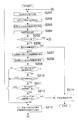
<第2コントローラ12の動作>
次に第2コントローラ12の動作について説明する。
図5及び図6は、第2コントローラの動作を説明するためのフローチャートを示す図である。
ステップ201〜204までは、第1コントローラ11の動作(図4参照)におけるステップ101〜104と同様であるため説明は省略する。<Operation of
Next, the operation of the
5 and 6 are flowcharts for explaining the operation of the second controller.
Steps 201 to 204 are the same as
ステップ204にて、第2制御部12aのメモリに記憶された制御情報を更新した後、現在、バックアップ動作中であるか否かが判断される(ステップ205)。
「バックアップ動作中」とは、モータ50、チャイム71及び表示灯72等への電力供給が第2コントローラ12から行われる状態をいう。当該バックアップ動作中であるか否かは、第1リレー13及び第2リレー14の開閉状況に基づいて判断される。具体的には、第1リレー13が開で、第2リレー14が閉となっている場合は、バックアップ動作中であると判断される。In step 204, after updating the control information stored in the memory of the
“During backup operation” refers to a state where power is supplied from the
◆バックアップ動作中ではない場合(ステップ205:NO)
バックアップ動作中ではない場合は(ステップ205:NO)、第2コントローラ12及びこれに接続された所定の検知手段(ホール素子55)等からなる制御系(以下、2系という)の故障の有無が判断される(ステップ206)。当該判断は、以下のようにして行われる。
(1)モータ50が駆動している状態であれば、モータ50の回転情報がホール素子55から第2制御部12aにフィードバックされるが、当該ホール素子55からの回転パルスが受信できないなど、ホール素子55の異常が発見された場合は、2系の故障とみなす。
(2)ドライバ部12dに電流センサを設け、当該電流センサで過電流が検知された場合は、ドライバ部12dの故障、即ち、2系の故障とみなす。
尚、これに限らず、その他の故障検知手段の検知結果に基づいて、2系の故障を判断してもよい。◆ When backup is not in progress (step 205: NO)
If the backup operation is not in progress (step 205: NO), whether or not there is a failure in the control system (hereinafter referred to as system 2) including the
(1) If the
(2) When a current sensor is provided in the
However, the present invention is not limited to this, and the failure of the second system may be determined based on the detection result of other failure detection means.
上記のように2系が故障しているとみなされた場合は(ステップ206:YES)、第2制御部12aは、第1制御部11aへの2系正常信号をOFFにする(ステップ214)。
When it is determined that the second system has failed as described above (step 206: YES), the
2系の故障が検知されなかった場合(ステップ206:NO)は、伝送部12cから他ドアの制御情報(他のドア制御装置10から送信された制御情報)を受信する(ステップ207)。
また、伝送部12cから1系の制御情報(第1コントローラ11から送信された制御情報)を受信する(ステップ208)。When the failure of the second system is not detected (step 206: NO), the control information of the other door (control information transmitted from the other door control device 10) is received from the
Further, the control information of the first system (control information transmitted from the first controller 11) is received from the
ステップ208において、第1コントローラ11から制御情報が送信されておらず、当該制御情報を受信できずに所定時間経過した場合は(ステップ209:NO)、1系が故障していると判断し、リレー駆動部12fにより、リレー13,14,15を第2状態(第1リレー13及び第3リレー15を開、第2リレー14を閉)に切り替える(ステップ213)。これにより、モータ50の制御は、第1コントローラ11による制御から第2コントローラ12による制御に切り替わる。また、第2制御部12aは、1系が故障した旨の1系故障情報を伝送部12cを介してローカル通信線32に送信する(ステップ213)。
In step 208, if the control information is not transmitted from the
第1コントローラ11から制御情報を所定時間内に受信できた場合は(ステップ209:YES)、第1コントローラ11から1系の故障情報(図4のステップ111参照)が送信されているか否かを判断する(ステップ210)。
第2制御部12aが伝送部12cを介して1系の故障情報を受信していれば(ステップ210:YES)、第2制御部12aは、リレー駆動部12fにより、リレー13,14,15を第2状態(第1リレー13及び第3リレーを開、第2リレー14を閉)に切り替え、1系故障情報を伝送部12cを介してローカル通信線32に送信する(ステップ213)。If the control information can be received from the
If the
第1コントローラ11から1系の故障情報が送信されていない場合は(ステップ210:NO)、ステップ208にて受信した第1コントローラ11の制御情報(1系の制御情報)と、第2コントローラ12自身の制御情報(2系の制御情報)とが一致するか否かを判断する(ステップ211)。具体的には、(1)開閉制御情報、(2)制御パラメータ情報((a)伝送指令認識情報、(b)開許可情報、(c)検知情報)が、1系と2系とで互いに一致しているか否かが判断される。
When failure information of the first system is not transmitted from the first controller 11 (step 210: NO), the control information (first system control information) of the
1系と2系とで制御情報が一致する場合は(ステップ211:YES)、ステップ201に戻り、伝送部11cからの新たな指令を待つ。
一方、1系と2系とで制御情報が一致しない場合は(ステップ211:NO)、当該1系の制御情報と、他のドア制御装置10から送信された制御情報とが一致するか否かを判断する(ステップ212)。When the control information matches between the first system and the second system (step 211: YES), the process returns to step 201 and waits for a new command from the
On the other hand, when the control information does not match between the 1st system and the 2nd system (step 211: NO), whether the control information of the 1st system matches the control information transmitted from the other
本実施形態においては、第2制御部12aは、当該1系の制御情報と、当該第2制御部12aを有するドア制御装置10と同じローカル通信線32上に接続された他の7つのドア制御装置10における1つのドア制御装置10から送信された制御情報と、を比較する。
具体的には、ローカル通信線32上において、通信端末31に近いドア制御装置10から順に、ドア制御装置10−1、ドア制御装置10−2、・・・、ドア制御装置10−8、とすると、ドア制御装置10−1の第2制御部は、当該ドア制御装置10−1における1系の制御情報と、ドア制御装置10−2の制御情報とを比較する。
同様にドア制御装置10−2、10−3、・・・、10−7の第2制御部は、それぞれ、自身の1系の制御情報と、ドア制御装置10−3、10−4、・・・、10−8の制御情報とを比較する。ドア制御装置10−8の第2制御部は、自身の1系の制御情報と、ドア制御装置10−1の制御情報とを比較する。In the present embodiment, the
Specifically, on the
Similarly, the second control units of the door control devices 10-2, 10-3,..., 10-7 each have their own system 1 control information and the door control devices 10-3, 10-4,. .. Compare with control information of 10-8. The second control unit of the door control device 10-8 compares its own 1-system control information with the control information of the door control device 10-1.
尚、当該ステップでは、ステップ211と同様に、(1)開閉制御情報、(2)制御パラメータ情報((a)伝送指令認識情報、(b)開許可情報、(c)検知情報)が互いに一致しているか否かが判断される。 In this step, as in step 211, (1) opening / closing control information, (2) control parameter information ((a) transmission command recognition information, (b) opening permission information, (c) detection information) are mutually identical. It is determined whether or not it is done.
1系の制御情報と他のドア制御装置10の制御情報とが一致する場合は(ステップ212:YES)、2系が故障していると判断し、2系正常信号をOFFにする(ステップ214)。即ち、1系の制御情報と他のドア制御装置10の制御情報とが一致し、2系の制御情報のみが異なっているため、2系の故障と判断する。
When the control information of the first system matches the control information of the other door control device 10 (step 212: YES), it is determined that the second system has failed and the second system normal signal is turned off (step 214). ). That is, since the control information of the first system matches the control information of the other
1系の制御情報と他のドア制御装置10の制御情報とが一致しない場合は(ステップ212:NO)、1系が故障していると判断し、リレー駆動部12fにより、リレー13,14,15を第2状態(第1リレー13及び第3リレーを開、第2リレー14を閉)に切り替え、1系故障情報を伝送部12cを介してローカル通信線32に送信する(ステップ213)。即ち、1系の制御情報は、他のドア制御装置10の制御情報、及び第2制御部12aの制御情報のいずれとも異なっているため、1系の故障と判断する。
When the control information of the first system and the control information of the other
ステップ213にて、リレー13,14,15が第2状態に切り替えられ、1系故障情報が伝送部12cを介してローカル通信線32に送信された後、図6に示すように、ステップ105で行われる動作と同様に、第2制御部12aにより、更新された当該第2制御部12aの制御情報が、伝送部12cを介してローカル通信線32に送信される(ステップ215)。
また、第2制御部12aは、当該第2制御部12aの更新された制御情報に基づいて、ドア101の開閉動作を開始、即ち、モータ50の駆動を開始する。同時に、表示灯72、チャイム71などへの接点出力を開始する(ステップ216)。In step 213, the
Further, the
モータ50の駆動を開始させた後、第2コントローラ12及びこれに接続された所定の検知手段(ホール素子55)等からなる制御系の故障の有無が判断される(ステップ217)。当該判断は、第1コントローラ11のステップ107と同様に、(1)ホール素子55から第2制御部12aにフィードバックされる回転情報が第2制御部12aがモータ50を回転しようと意図していた回転状態と一致するか否かの検知結果、(2)ドライバ部12dに設けられた電流センサでの過電流の検知結果、などに基づいてなされる。
After starting the driving of the
尚、これに限らず、その他の故障検知手段の検知結果に基づいて、2系の故障を判断してもよい。
例えば、伝送部12cで他のドア制御装置10の制御情報を受信し、当該制御情報と自己(2系)の制御情報とを比較して、2系の故障の有無を判断してもよい。However, the present invention is not limited to this, and the failure of the second system may be determined based on the detection result of other failure detection means.
For example, the
上記のように2系が故障しているとみなされた場合は(ステップ217:YES)、第2制御部12aは、モータ50の駆動を停止するとともに、チャイム71、表示灯72などへの接点出力を停止する(ステップ218)。そして、第2制御部12aは、2系が故障した旨の2系故障情報を伝送部12cを介してローカル通信線32に送信する。(ステップ219)。
一方、2系の故障が検知されなかった場合は(ステップ217:NO)、第2制御部12aは、モータ50の制御及び接点出力を継続して行いながら、ステップ201に戻って伝送部12cからの新たな指令を待つことになる。When it is considered that the second system has failed as described above (step 217: YES), the
On the other hand, when the failure of the second system is not detected (step 217: NO), the
◆バックアップ動作中である場合(ステップ205:YES)
バックアップ動作中である場合(ステップ205:YES)は、第2制御部12aは、図6に示すステップ215〜ステップ219に従って動作する。尚、当該ステップ215〜ステップ219については、ステップ213の後工程として上述しているため、ここでの説明は省略する。◆ When backup is in progress (step 205: YES)
When the backup operation is being performed (step 205: YES), the
<本実施形態の効果>
以上説明したように、本実施形態に係る鉄道車両用ドア制御システム1は、以下の効果を奏する。<Effect of this embodiment>
As described above, the railcar door control system 1 according to the present embodiment has the following effects.
(1)
鉄道車両用ドア制御システム1は、鉄道車両100の複数のドア101にそれぞれ設けられて当該ドア101の開閉を制御する複数のドア制御装置10と、複数のドア制御装置10が接続されたローカル通信線32と、を備え、運転台の列車情報制御装置20から指令通信線30及び信号線40を介して、複数のドア制御装置10へ一括して送信される指令に基づいてドア101が開閉されるシステムである。
そして、複数のドア制御装置10の各ドア制御装置10は、ドア101を開閉させるための一のモータ50と、列車情報制御装置20からの指令に基づいてモータ50を制御可能な第1コントローラ11及び第2コントローラ12とを備える。
第2コントローラ12は、第1コントローラ11がモータ50の制御を行っているとき(つまり、第1リレー13が閉、第2リレー14が開の状態のとき)に、第1コントローラ11及び他のドア制御装置10から送信される制御情報をローカル通信線32から取得し、第1コントローラ11の制御情報が、自己(第2コントローラ12)の制御情報及び他のドア制御装置10の制御情報のいずれとも異なる場合は、モータ50の制御を、第1コントローラ11による制御から第2コントローラ12による制御に切り替える(つまり、第1リレー13を開、第2リレー14を閉とする)。(1)
The railway vehicle door control system 1 is provided in each of a plurality of
Each
When the
この構成によると、例えば、第1コントローラ11が故障して、当該第1コントローラ11の制御情報が不適切なものになった場合には、故障した第1コントローラ11によるモータ50の制御は停止される。これにより、不適切な制御情報に基づいてモータ50が駆動されることを防止することができ、安全性を確保することができる。
また、第1コントローラ11の制御情報が不適切である場合は、モータ50の制御は、第1コントローラ11から第2コントローラ12によるものに切り替えられるので、制御対象のドア101の動作を長時間停止することはない。これにより、ドア101の継続した運用が可能となる。According to this configuration, for example, when the
In addition, when the control information of the
また、各ドア制御装置10が、独立して分散制御により故障診断及び制御の切り替えを行うため、列車情報制御装置20などの上位システムを介して処理する場合に比べ、上位システムや車両間を結ぶ通信線の信頼性の影響を受けずに済む。
In addition, since each
尚、本実施形態においては、1系、2系、他のドア制御装置との間で比較する制御情報として、開閉制御情報及び制御パラメータ情報(伝送指令認識情報、開許可情報、及び検知情報)を用いているが、この場合に限定されない。例えば、伝送指令認識情報及び開許可情報のみを、1系、2系、他ドアとの間で比較する構成であってもよい。 In this embodiment, as control information to be compared with the 1st system, 2nd system, and other door control devices, opening / closing control information and control parameter information (transmission command recognition information, opening permission information, and detection information) However, the present invention is not limited to this case. For example, the configuration may be such that only the transmission command recognition information and the opening permission information are compared with the 1st system, 2nd system, and other doors.
また、2系の制御情報と他のドア制御装置の制御情報とが一致しない場合は、モータ50の制御を第1コントローラ11から第2コントローラ12に切り替えないように構成してもよい。この構成では、2系の故障の可能性が高い場合は、第2コントローラ12への切り替えが防止される。
Further, when the control information of the second system and the control information of another door control device do not match, the control of the
(2)
第1コントローラ11は、自己(第1コントローラ11)の故障を検知可能であって、自己の故障を検知すると、自己によるモータ50の制御を中止するとともに、故障情報をローカル通信線32に出力するように構成されている。
第2コントローラ12は、第1コントローラ11から出力された故障情報をローカル通信線32から取得した場合は、モータ50の制御を、第1コントローラ11による制御から当該第2コントローラ12による制御に切り替える。(2)
The
When the failure information output from the
この構成によると、第1コントローラ11は、自己の故障を検知して、故障情報をローカル通信線32に出力するので、第1コントローラ11自身で検知可能な故障については、第2コントローラ12が第1コントローラ11に関する情報を解析して判断する必要はない。そのため、第1コントローラ11からローカル通信線32に出力される制御情報は、自己で判断できない故障を第2コントローラ12が判断するために必要な情報だけに減らすことができる。これにより、第1コントローラ11から送信する制御情報の内容を過度に増やすことなく、第1コントローラ11の故障を第2コントローラ12が検知できるようになる。
According to this configuration, the
(3)
第2コントローラ12は、自己の故障を検知可能であって、自己の故障を検知すると、故障情報を第1コントローラ11に通知する。
第1コントローラ11は、第2コントローラ12から故障情報が通知されると、当該故障情報をローカル通信線32に出力するように構成されている(3)
The
The
この構成によると、第2コントローラ12が故障した場合にも第1コントローラ11でモータ50の制御を継続しつつ、通信端末31を介して列車情報制御装置20に、冗長性が無くなったことを通知することができる。
According to this configuration, even when the
(4)
ドア制御装置10は、第1コントローラ11からモータ50への出力線に設けられた第1リレー13(第1出力線リレー)と、第2コントローラ12からモータ50への出力線に設けられた第2リレー14(第2出力線リレー)と、第1コントローラ11に対して電源からの電力を供給する給電線21に設けられた第3リレー15(給電線リレー)と、を備えている。
第2コントローラ12は、第1コントローラ11から出力された故障情報を取得した場合は、第1リレー13及び第3リレー15を開くとともに、第2リレー14を閉じる。
尚、第1コントローラ11から故障情報が出力されていないときは、第1リレー13及び第3リレー15は閉状態、第2リレー14は開状態とされている。(4)
The
When acquiring the failure information output from the
When failure information is not output from the
この構成によると、仮に、第1コントローラ11が暴走したとしても、第2コントローラ12に悪影響を与えないように、第1コントローラ11を確実に切り離すことができる。
According to this configuration, even if the
(5)
モータ50には、第1コントローラ11に検知結果を出力するホール素子54(第1エンコーダ)と、第2コントローラ12に検知結果を出力するホール素子55(第2エンコーダ)とが設けられている。
また、第1コントローラ11及び第2コントローラ12の双方が、それぞれ、CPUを有する制御部11a,12aと、列車情報制御装置20から信号線40を介して送信される信号を制御部11a,12aに入力するための電気回路からなる信号入力部11b,12b(信号入力用電気回路)と、ローカル通信線32に制御部11a,12aからの情報を出力できるとともにローカル通信線32に送信された情報を制御部11a,12aに入力可能な電気回路からなる伝送部11c,12c(情報入出力用電気回路)と、モータ50に電力を供給するための、電気回路からなるドライバ部11d,12d(モータ出力用電気回路)とを備えている。(5)
The
Moreover, both the
この構成によると、故障の可能性が比較的低い部品(モータ50、ロック検知手段61、全閉位置検知手段62、手動解錠検知手段63、チャイム71、表示灯72)は共用とすることで、省スペース化を図り、コストの増加を抑えることができる。
一方、故障の可能性が比較的高い部品(ホール素子54、55、制御部11a,12a、信号入力部11b,12b、伝送部11c,12c、ドライバ部11d,12d)は各コントローラ11,12に設けることで、冗長性を高めることができる。
According to this configuration, parts that have a relatively low possibility of failure (
On the other hand, parts possibility of a failure is not relatively high (
(6)
尚、リレー13,14,15が第1状態(第1リレー13及び第3リレー15が閉、第2リレー14が開)となっているとき(即ち、第1コントローラ11でモータ50が制御されているとき)は、第2コントローラ12のドライバ部12dへの給電を停止し、当該リレー13,14,15が第2状態(第1リレー13及び第3リレー15が開、第2リレー14が閉)に切り替わるときに、ドライバ部12dへの給電が開始されるように構成してもよい。(6)
The
この構成によると、モータ50を第1コントローラ11で制御しているときは、第1コントローラ11の監視に不要なドライバ部12dへの給電が停止されるので、当該ドライバ部12dの劣化による故障発生を軽減することができる。
According to this configuration, when the
(7)
また、鉄道車両用ドア制御システム1は、次のように変形して実施することもできる。
即ち、上記鉄道車両用ドア制御システム1において、第2コントローラ12の動作を以下のように変更してもよい。
第2コントローラ12は、第1コントローラ11がモータ50の制御を行っているときに、第1コントローラ11及び同じローカル通信線32に接続される他の7つのドア制御装置10から送信される制御情報をローカル通信線32から取得し、(a)第1コントローラ11の制御情報、第2コントローラ12の制御情報、及び他の7つのドア制御装置10の制御情報(合計9つの制御情報)のうちの少なくとも半数が一致しており、且つ、(b)当該一致する制御情報と第1コントローラ11の制御情報とが異なり、且つ、(c)当該一致する制御情報と第2コントローラ12の制御情報とが一致する場合は、モータ50等の制御を、第1コントローラ11による制御から第2コントローラ12による制御に切り替える。(7)
In addition, the railway vehicle door control system 1 can be implemented by being modified as follows.
That is, in the railway vehicle door control system 1, the operation of the
The
例えば、第1コントローラ11の制御情報が第2コントローラ12の制御情報と異なる場合であって、当該第2コントローラ12の制御情報及び他の4つのドア制御装置10の制御情報が一致している場合には、モータ50の制御は第2コントローラ12による制御に切り替わる。
For example, when the control information of the
この構成によると、第1コントローラ11の制御情報、第2コントローラ12の制御情報、及び他の7つのドア制御装置10の制御情報(合計9つの制御情報)に基づいて、1系の故障の有無が判断されるので、鉄道車両用ドア制御システム1の構成に対して別途装置を追加することなく、1系の故障の有無の判断をより正確に行うことができる。即ち、他の複数のドア制御装置10の制御情報と2系の制御情報とを用いて、1系の故障の有無を判断することができるため、他の一のドア制御装置10の制御情報と2系の制御情報とを用いて、1系の故障の有無を判断する場合に比べて、より正確に1系の故障の有無を判断することができる。
According to this configuration, based on the control information of the
また、第1コントローラ11が故障しており、且つ、第2コントローラ12が故障していない場合を、制御情報の簡易な比較によって、より正確に判断できる。そのため、モータ50の制御が、故障した第2コントローラ12に切り替えられてしまうことを防ぐことができる。
Further, the case where the
以上、本発明の実施形態について説明したが、本発明は上述の実施の形態に限られるものではなく、特許請求の範囲に記載した限りにおいて様々に変更して実施することができるものである。 Although the embodiments of the present invention have been described above, the present invention is not limited to the above-described embodiments, and various modifications can be made as long as they are described in the claims.
(1)ドア101は、ラックアンドピニオン方式で駆動するものに限らず、ベルトタイプやボールねじタイプであってもよい。
(1) The
(2)通信端末31は、複数の車両が連結された鉄道車両100の一つの車両に対して一台設ける場合に限らず、複数の車両に対して一台設けてもよい。つまり、複数の車両に跨ってローカル通信線32が延びていてもよい。
(2) The
(3)第2コントローラ12が各種信号を受け取るときのソフトフィルタの時定数を第1コントローラ11よりも長く設定してもよい。これにより、ノイズ等の影響を第1コントローラ11よりも受けにくくすることができる。
(3) The time constant of the soft filter when the
(4)第1コントローラ11が、自己の故障を検知するために、以下のように構成してもよい。尚、第2コントローラ12が自己の故障を検知する場合も同様に構成できる。
(4) The
第1コントローラ11が、(a1)ロック検知手段61から、全閉位置でロック状態であることを示す信号を取得しており、且つ、全閉位置検知手段62からドア101が全閉位置にあることを示す信号を取得していない場合、又は(a2)ロック検知手段61から、全閉位置でロック状態であることを示す信号を取得しておらず、且つ、全閉位置検知手段62からドア101が全閉位置にあることを示す信号を取得している場合、には次のように判断する。
The
第1コントローラ11は、第2コントローラ12の制御情報を取得し、当該制御情報に基づいて、当該第2コントローラ12においても、当該ロック検知手段61及び全閉位置検知手段62からの信号の取得状態が、上記第1コントローラ11と一致する場合は、ロック検知手段61又は全閉位置検知手段62の故障(リミットスイッチの故障)と考えられ、当該ロック検知手段61及び全閉位置検知手段62からの信号のみによっては第1コントローラ11の故障とはみなさない。
一方、第2コントローラ12において、当該ロック検知手段61及び全閉位置検知手段62からの信号の取得状態が、次の(b1)又は(b2)となる場合は、1系における信号の取得経路にて異常が発生したとみなし、1系の故障とみなす。
(b1)ロック検知手段61から、全閉位置でロック状態であることを示す信号を取得しており、且つ、全閉位置検知手段62からドア101が全閉位置にあることを示す信号を取得している。
(b2)ロック検知手段61から、全閉位置でロック状態であることを示す信号を取得しておらず、且つ、全閉位置検知手段62からドア101が全閉位置にあることを示す信号を取得していない。The
On the other hand, in the
(B1) A signal indicating that the door is in the fully closed position is acquired from the
(B2) A signal indicating that the
この構成によると、ロック検知手段61及び全閉位置検知手段62からの信号を1系と2系とで比較することで容易にコントローラ11,12の故障を検知できるとともに、ロック検知手段61及び全閉位置検知手段62の故障も検知することができる。
According to this configuration, the failure of the
本発明は、鉄道車両用のドアの開閉を制御するために用いることができる。 The present invention can be used to control opening and closing of a door for a railway vehicle.
1 鉄道車両用ドア制御システム
10 ドア制御装置
11 第1コントローラ
12 第2コントローラ
13、14、15 リレー
20 列車情報制御装置
30 指令通信線
32 ローカル通信線
40 信号線
50 モータ
54、55 ホール素子(エンコーダ)
100 鉄道車両
101 ドアDESCRIPTION OF SYMBOLS 1 Rail vehicle
100
Claims (8)
前記ドア制御装置は、
ドアを開閉させるための一つのモータと、
前記運転台からの指令に基づいて前記モータを制御可能な第1コントローラ及び第2コントローラと、
を備え、
前記第2コントローラは、前記第1コントローラが前記モータの制御を行っているときに、前記第1コントローラ及び他のドア制御装置から送信される制御情報を前記通信線から取得し、前記第1コントローラの制御情報が、自己の制御情報及び他のドア制御装置の制御情報のいずれとも異なる場合は、前記モータの制御を、前記第1コントローラによる制御から当該第2コントローラによる制御に切り替える、鉄道車両用ドア制御システム。A plurality of door control devices that are respectively provided on a plurality of doors of a railway vehicle and control opening and closing of the doors; and a communication line to which the plurality of door control devices are connected. A door control system for a railway vehicle in which a door is opened and closed based on a command transmitted to the apparatus in a batch,
The door control device includes:
One motor to open and close the door;
A first controller and a second controller capable of controlling the motor based on a command from the cab;
With
The second controller acquires control information transmitted from the first controller and another door control device from the communication line when the first controller is controlling the motor, and the first controller If the control information is different from both the control information of its own and the control information of another door control device, the control of the motor is switched from the control by the first controller to the control by the second controller. Door control system.
前記第2コントローラは、前記第1コントローラから出力された故障情報を前記通信線から取得した場合は、前記モータの制御を、前記第1コントローラによる制御から当該第2コントローラによる制御に切り替える、
請求項1に記載の鉄道車両用ドア制御システム。The first controller is configured to detect a self-failure, and when detecting the self-failure, the first controller stops the control of the motor by the self and outputs failure information to the communication line,
When the second controller acquires the failure information output from the first controller from the communication line, the control of the motor is switched from the control by the first controller to the control by the second controller.
The railway vehicle door control system according to claim 1.
前記第1コントローラは、前記第2コントローラから故障情報が通知されると、当該故障情報を前記通信線に出力するように構成されている、
請求項1又は2に記載の鉄道車両用ドア制御システム。The second controller is capable of detecting its own failure, and when detecting its own failure, notifies the first controller of failure information,
When the failure information is notified from the second controller, the first controller is configured to output the failure information to the communication line.
The door control system for a railway vehicle according to claim 1 or 2.
前記第1コントローラから前記モータへの出力線に設けられた第1出力線リレーと、
前記第2コントローラから前記モータへの出力線に設けられた第2出力線リレーと、
前記第1コントローラに対して電源からの電力を供給する給電線に設けられた給電線リレーと、
を備え、
前記第2コントローラは、前記第1コントローラから出力された故障情報を取得した場合は、前記給電線リレー及び前記第1出力線リレーを開くとともに、前記第2出力線リレーを閉じる、
請求項1〜3のいずれか一項に記載の鉄道車両用ドア制御システム。The door control device includes:
A first output line relay provided on an output line from the first controller to the motor;
A second output line relay provided on an output line from the second controller to the motor;
A power line relay provided on a power line for supplying power from a power source to the first controller;
With
When the second controller acquires the failure information output from the first controller, it opens the feeder line relay and the first output line relay and closes the second output line relay.
The door control system for rail vehicles as described in any one of Claims 1-3.
前記第1コントローラ及び前記第2コントローラの双方が、CPUを有する制御部と、前記通信線に前記制御部からの情報を出力できるとともに前記通信線からの情報を前記制御部に入力可能な情報入出力用電気回路と、前記モータに電力を供給するためのモータ出力用電気回路とを備えている、
請求項1〜4のいずれか一項に記載の鉄道車両用ドア制御システム。The motor is provided with a first encoder that outputs a detection result to the first controller, and a second encoder that outputs a detection result to the second controller,
Both the first controller and the second controller can output information from the control unit to the control unit having a CPU and the communication line, and can input information from the communication line to the control unit. An output electric circuit, and a motor output electric circuit for supplying electric power to the motor,
The door control system for rail vehicles as described in any one of Claims 1-4.
請求項5に記載の鉄道車両用ドア制御システム。When the first controller is controlling the motor, power supply to the electric circuit for motor output in the second controller is stopped.
The railway vehicle door control system according to claim 5.
前記ドア制御装置は、
ドアを開閉させるための一つのモータと、
運転台から前記通信線を介して前記複数のドア制御装置へ一括して送信される指令に基づいて前記モータを制御可能な第1コントローラ及び第2コントローラと、
を備え、
前記第2コントローラは、前記第1コントローラが前記モータの制御を行っているときに、前記第1コントローラ及び他の複数のドア制御装置から送信される制御情報を前記通信線から取得し、当該第1コントローラの制御情報、前記第2コントローラの制御情報、及び前記他の複数のドア制御装置の制御情報に基づいて、前記モータの制御を、前記第1コントローラによる制御から当該第2コントローラによる制御に切り替える、鉄道車両用ドア制御システム。A railway vehicle door control system comprising a plurality of door control devices that are respectively provided on a plurality of doors of a railway vehicle and control opening and closing of the doors, and a communication line connected to the plurality of door control devices. ,
The door control device includes:
One motor to open and close the door;
A first controller and a second controller capable of controlling the motor based on a command transmitted collectively from the cab to the plurality of door control devices via the communication line;
With
The second controller acquires control information transmitted from the first controller and a plurality of other door control devices from the communication line when the first controller is controlling the motor. Based on the control information of one controller, the control information of the second controller, and the control information of the plurality of other door control devices, the control of the motor is changed from the control by the first controller to the control by the second controller. Switching door control system for railway vehicles.
(a)前記第1コントローラの制御情報、前記第2コントローラの制御情報、及び前記他の複数のドア制御装置の制御情報のうちの少なくとも半数が一致しており、且つ、
(b)当該一致する制御情報と前記第1コントローラの制御情報とが異なり、且つ、
(c)当該一致する制御情報と前記第2コントローラの制御情報とが一致する、
場合は、前記モータの制御を、前記第1コントローラによる制御から当該第2コントローラによる制御に切り替える、
請求項7に記載の鉄道車両用ドア制御システム。The second controller acquires control information transmitted from the first controller and the plurality of other door control devices from the communication line when the first controller is controlling the motor,
(A) At least half of the control information of the first controller, the control information of the second controller, and the control information of the other plurality of door control devices match, and
(B) the matching control information is different from the control information of the first controller, and
(C) The matching control information matches the control information of the second controller.
In this case, the control of the motor is switched from the control by the first controller to the control by the second controller.
The door control system for a railway vehicle according to claim 7.
Priority Applications (1)
| Application Number | Priority Date | Filing Date | Title |
|---|---|---|---|
| JP2011502691A JP5117614B2 (en) | 2009-03-03 | 2010-02-01 | Rail vehicle door control system |
Applications Claiming Priority (4)
| Application Number | Priority Date | Filing Date | Title |
|---|---|---|---|
| JP2009049395 | 2009-03-03 | ||
| JP2009049395 | 2009-03-03 | ||
| JP2011502691A JP5117614B2 (en) | 2009-03-03 | 2010-02-01 | Rail vehicle door control system |
| PCT/JP2010/051349 WO2010100988A1 (en) | 2009-03-03 | 2010-02-01 | Door control system for railroad vehicle |
Publications (2)
| Publication Number | Publication Date |
|---|---|
| JPWO2010100988A1 JPWO2010100988A1 (en) | 2012-09-06 |
| JP5117614B2 true JP5117614B2 (en) | 2013-01-16 |
Family
ID=42709551
Family Applications (1)
| Application Number | Title | Priority Date | Filing Date |
|---|---|---|---|
| JP2011502691A Active JP5117614B2 (en) | 2009-03-03 | 2010-02-01 | Rail vehicle door control system |
Country Status (6)
| Country | Link |
|---|---|
| EP (1) | EP2404805B1 (en) |
| JP (1) | JP5117614B2 (en) |
| KR (1) | KR101268755B1 (en) |
| CN (1) | CN102341288B (en) |
| TW (1) | TW201041768A (en) |
| WO (1) | WO2010100988A1 (en) |
Cited By (1)
| Publication number | Priority date | Publication date | Assignee | Title |
|---|---|---|---|---|
| US12084897B2 (en) | 2021-03-25 | 2024-09-10 | Fuji Electric Co., Ltd. | Control apparatus and control method |
Families Citing this family (36)
| Publication number | Priority date | Publication date | Assignee | Title |
|---|---|---|---|---|
| JP5804308B2 (en) * | 2011-05-17 | 2015-11-04 | 富士電機株式会社 | Railway vehicle monitoring system |
| CN102606023A (en) * | 2012-03-20 | 2012-07-25 | 南京康尼电子科技有限公司 | Screen door control device and screen door control method |
| KR101490022B1 (en) * | 2013-05-02 | 2015-02-16 | 한국산업은행 | Apparatus for controlling automatic door |
| JP5631444B1 (en) | 2013-05-27 | 2014-11-26 | タナシン電機株式会社 | Leakage current calculation device and leakage current calculation method |
| JP6327413B2 (en) * | 2013-07-18 | 2018-05-23 | 株式会社ニシヤマ | Image synchronization apparatus, measurement system, and image synchronization method |
| JP6209905B2 (en) * | 2013-09-04 | 2017-10-11 | 富士電機株式会社 | Door control device |
| DE102013110462A1 (en) * | 2013-09-23 | 2015-03-26 | Knorr-Bremse Systeme für Nutzfahrzeuge GmbH | Integrated and combined door operating system for commercial vehicles |
| CN103670114B (en) * | 2013-11-25 | 2016-02-10 | 唐山轨道客车有限责任公司 | train door control method and device |
| CN103676740A (en) * | 2013-12-09 | 2014-03-26 | 南京康尼电子科技有限公司 | Safety control circuit based on CPLD |
| DE202014100845U1 (en) * | 2014-02-25 | 2014-04-09 | Stabilus Gmbh | Side door assembly |
| AT515888A3 (en) * | 2014-05-22 | 2019-01-15 | Knorr Bremse Gmbh | Electronic circuit for safely closing a motor-driven door of a rail vehicle |
| CN104806107B (en) * | 2015-04-14 | 2016-06-08 | 今创集团股份有限公司 | There is the door controller of safety relay |
| CN106123248B (en) * | 2016-08-22 | 2019-01-04 | 南京康尼电子科技有限公司 | A kind of urban track traffic Electric air valve control system |
| WO2018053693A1 (en) * | 2016-09-20 | 2018-03-29 | 深圳市大疆创新科技有限公司 | Motor control system and unmanned aircraft |
| JP7027808B2 (en) * | 2016-11-11 | 2022-03-02 | 株式会社デンソー | Rotating electric machine control device and electric power steering device using this |
| JP7011901B2 (en) * | 2017-06-27 | 2022-02-10 | コイト電工株式会社 | Control device and lighting system |
| JP6949603B2 (en) * | 2017-07-27 | 2021-10-13 | 株式会社鈴木シャッター | Shutter device |
| DE102017122816A1 (en) * | 2017-09-29 | 2019-04-04 | Knorr-Bremse Gesellschaft Mit Beschränkter Haftung | Control unit and method for controlling a door drive motor for a door of a rail vehicle |
| KR20190052449A (en) | 2017-11-08 | 2019-05-16 | 서정랑 | endurance test system of motor for a door of train |
| KR20190052453A (en) | 2017-11-08 | 2019-05-16 | 박정희 | defection detecting system of DC motor for a door of train and detecting method thereof |
| JP7220056B2 (en) * | 2018-11-08 | 2023-02-09 | ナブテスコ株式会社 | Notification device and door operator |
| JP7236861B2 (en) * | 2018-12-26 | 2023-03-10 | ナブテスコ株式会社 | door controller |
| JP7226092B2 (en) | 2019-05-22 | 2023-02-21 | 株式会社デンソー | shift range controller |
| KR200491573Y1 (en) | 2019-05-27 | 2020-04-29 | 서정랑 | endurance test system of motor for a door of train |
| CN110211462B (en) * | 2019-05-31 | 2024-07-23 | 广州市轻工技师学院(广州市轻工高级技工学校、广州市轻工高级职业技术培训学院) | Train automatically-controlled door control circuit wiring training device |
| KR200491574Y1 (en) | 2019-06-19 | 2020-04-28 | 박정희 | defection detecting system of DC motor for a door of train |
| CN111196287B (en) * | 2020-01-20 | 2022-02-25 | 南京康尼机电股份有限公司 | Rail vehicle door system area controller and rail vehicle door system |
| CN113622784A (en) * | 2020-05-07 | 2021-11-09 | 北京京乾锐机电设备有限公司 | Shielding door controller |
| US20220081950A1 (en) * | 2020-09-11 | 2022-03-17 | International Truck Intellectual Property Company, Llc | Door condition monitoring |
| JP6954487B1 (en) * | 2021-03-25 | 2021-10-27 | 富士電機株式会社 | Monitoring device, monitoring method |
| FR3123289B1 (en) | 2021-06-01 | 2023-10-20 | Faiveley Transp Tours | Control and drive assembly for a door of a transport vehicle, corresponding vehicle and method of implementation |
| JP7472858B2 (en) * | 2021-06-11 | 2024-04-23 | 富士電機株式会社 | Control device and control method |
| CN113859150B (en) * | 2021-09-28 | 2023-11-07 | 一汽解放汽车有限公司 | Vehicle control system |
| KR102578267B1 (en) * | 2022-07-18 | 2023-09-12 | 국방과학연구소 | Hatch drive system and method |
| CN115782935B (en) * | 2022-10-20 | 2025-03-28 | 株洲星联铁道车辆机电装备有限责任公司 | A safe and reliable automatic ground unloading system for railway freight hopper cars |
| KR102624433B1 (en) * | 2023-03-24 | 2024-01-15 | 인터콘시스템스 주식회사 | Integrated door control device for train doors |
Citations (14)
| Publication number | Priority date | Publication date | Assignee | Title |
|---|---|---|---|---|
| JPH06219310A (en) * | 1993-01-22 | 1994-08-09 | Nissan Motor Co Ltd | Fail safe device of controller |
| JPH09301161A (en) * | 1996-05-09 | 1997-11-25 | Nabco Ltd | Railway vehicle side door control device |
| JPH11180303A (en) * | 1997-12-18 | 1999-07-06 | Nabco Ltd | Monitoring device for rolling stock |
| JPH11180304A (en) * | 1997-12-18 | 1999-07-06 | Nabco Ltd | Monitoring device for rolling stock |
| JP2001301616A (en) * | 2000-04-25 | 2001-10-31 | Nabco Ltd | Side door control device for rolling stock |
| JP2005057904A (en) * | 2003-08-05 | 2005-03-03 | Koyo Seiko Co Ltd | Motor controller |
| JP2005130673A (en) * | 2003-10-27 | 2005-05-19 | Fuji Electric Systems Co Ltd | Control device for permanent magnet type synchronous motor |
| JP2005145240A (en) * | 2003-11-14 | 2005-06-09 | Fuji Electric Systems Co Ltd | Door drive control device |
| JP2005231441A (en) * | 2004-02-18 | 2005-09-02 | Hitachi Ltd | Platform door equipment |
| JP2005297670A (en) * | 2004-04-08 | 2005-10-27 | Kyosan Electric Mfg Co Ltd | Movable step device |
| JP2005349909A (en) * | 2004-06-09 | 2005-12-22 | Fuji Electric Systems Co Ltd | Door drive control device |
| JP2006290048A (en) * | 2005-04-06 | 2006-10-26 | Fuji Electric Systems Co Ltd | Door drive control device and door drive control method |
| JP2007001346A (en) * | 2005-06-21 | 2007-01-11 | Fuji Electric Systems Co Ltd | Door control device |
| JP2008296872A (en) * | 2007-06-04 | 2008-12-11 | Fuji Electric Systems Co Ltd | Vehicle door drive control device and door opening / closing control signal monitoring device |
Family Cites Families (2)
| Publication number | Priority date | Publication date | Assignee | Title |
|---|---|---|---|---|
| TW328190B (en) * | 1994-06-14 | 1998-03-11 | Toshiba Co Ltd | Control device of brushless motor and method of fault detection and air conditioner |
| JP2007280313A (en) * | 2006-04-12 | 2007-10-25 | Yokogawa Electric Corp | Redundant system |
-
2010
- 2010-02-01 WO PCT/JP2010/051349 patent/WO2010100988A1/en not_active Ceased
- 2010-02-01 EP EP10748585.6A patent/EP2404805B1/en not_active Not-in-force
- 2010-02-01 KR KR1020117022652A patent/KR101268755B1/en not_active Expired - Fee Related
- 2010-02-01 CN CN201080011732.0A patent/CN102341288B/en not_active Expired - Fee Related
- 2010-02-01 JP JP2011502691A patent/JP5117614B2/en active Active
- 2010-02-24 TW TW099105314A patent/TW201041768A/en not_active IP Right Cessation
Patent Citations (14)
| Publication number | Priority date | Publication date | Assignee | Title |
|---|---|---|---|---|
| JPH06219310A (en) * | 1993-01-22 | 1994-08-09 | Nissan Motor Co Ltd | Fail safe device of controller |
| JPH09301161A (en) * | 1996-05-09 | 1997-11-25 | Nabco Ltd | Railway vehicle side door control device |
| JPH11180303A (en) * | 1997-12-18 | 1999-07-06 | Nabco Ltd | Monitoring device for rolling stock |
| JPH11180304A (en) * | 1997-12-18 | 1999-07-06 | Nabco Ltd | Monitoring device for rolling stock |
| JP2001301616A (en) * | 2000-04-25 | 2001-10-31 | Nabco Ltd | Side door control device for rolling stock |
| JP2005057904A (en) * | 2003-08-05 | 2005-03-03 | Koyo Seiko Co Ltd | Motor controller |
| JP2005130673A (en) * | 2003-10-27 | 2005-05-19 | Fuji Electric Systems Co Ltd | Control device for permanent magnet type synchronous motor |
| JP2005145240A (en) * | 2003-11-14 | 2005-06-09 | Fuji Electric Systems Co Ltd | Door drive control device |
| JP2005231441A (en) * | 2004-02-18 | 2005-09-02 | Hitachi Ltd | Platform door equipment |
| JP2005297670A (en) * | 2004-04-08 | 2005-10-27 | Kyosan Electric Mfg Co Ltd | Movable step device |
| JP2005349909A (en) * | 2004-06-09 | 2005-12-22 | Fuji Electric Systems Co Ltd | Door drive control device |
| JP2006290048A (en) * | 2005-04-06 | 2006-10-26 | Fuji Electric Systems Co Ltd | Door drive control device and door drive control method |
| JP2007001346A (en) * | 2005-06-21 | 2007-01-11 | Fuji Electric Systems Co Ltd | Door control device |
| JP2008296872A (en) * | 2007-06-04 | 2008-12-11 | Fuji Electric Systems Co Ltd | Vehicle door drive control device and door opening / closing control signal monitoring device |
Cited By (1)
| Publication number | Priority date | Publication date | Assignee | Title |
|---|---|---|---|---|
| US12084897B2 (en) | 2021-03-25 | 2024-09-10 | Fuji Electric Co., Ltd. | Control apparatus and control method |
Also Published As
| Publication number | Publication date |
|---|---|
| EP2404805A1 (en) | 2012-01-11 |
| TWI378874B (en) | 2012-12-11 |
| CN102341288B (en) | 2014-07-16 |
| HK1164806A1 (en) | 2012-09-28 |
| EP2404805B1 (en) | 2020-09-30 |
| WO2010100988A1 (en) | 2010-09-10 |
| CN102341288A (en) | 2012-02-01 |
| EP2404805A4 (en) | 2017-01-18 |
| KR20110124786A (en) | 2011-11-17 |
| TW201041768A (en) | 2010-12-01 |
| JPWO2010100988A1 (en) | 2012-09-06 |
| KR101268755B1 (en) | 2013-05-29 |
Similar Documents
| Publication | Publication Date | Title |
|---|---|---|
| JPWO2010100988A1 (en) | Rail vehicle door control system | |
| KR101490022B1 (en) | Apparatus for controlling automatic door | |
| RU2604633C2 (en) | Interface unit, conveying system and method for monitoring operating condition of input circuit in safety circuit of conveying system | |
| EP1976734B1 (en) | Electronic control system for a vehicle | |
| JP4699004B2 (en) | Elevator equipment and elevator equipment monitoring system | |
| EP2790318B1 (en) | Electronic control device having power supply voltage monitoring function and vehicle steering control device equipped with same | |
| KR20100011872A (en) | Auto door controlling system comprising dual controllers | |
| US20250042447A1 (en) | Controller and control method | |
| JP4389975B2 (en) | Safety systems and safety equipment | |
| JP3902929B2 (en) | On-vehicle equipment | |
| JP2011195101A (en) | Control device | |
| CN116710342B (en) | Ropeway with vehicles having a closing drive and a fail-safe locking monitor | |
| CN102472075B (en) | Door control devices for vehicles | |
| JP2022149741A (en) | Control device, method for the same | |
| HK1164806B (en) | Door control system for railroad vehicle | |
| KR20150099153A (en) | Door control system for train | |
| JP2007283974A (en) | Vehicle power supply system | |
| JP2005343602A (en) | Elevator control device | |
| JP4894636B2 (en) | Vehicle door drive control device and door opening / closing control signal monitoring device | |
| JP2010137632A (en) | Anti-theft device for vehicle | |
| JP2011097726A (en) | Main controller | |
| KR101538220B1 (en) | Apparatus and method for controlling track circuit | |
| HK1122000B (en) | Method and apparatus for decommissioning faulty doors | |
| HK1122000A1 (en) | Method and apparatus for decommissioning faulty doors | |
| EA012739B1 (en) | Elevator system |
Legal Events
| Date | Code | Title | Description |
|---|---|---|---|
| A131 | Notification of reasons for refusal |
Free format text: JAPANESE INTERMEDIATE CODE: A131 Effective date: 20120828 |
|
| A521 | Request for written amendment filed |
Free format text: JAPANESE INTERMEDIATE CODE: A523 Effective date: 20120907 |
|
| TRDD | Decision of grant or rejection written | ||
| A01 | Written decision to grant a patent or to grant a registration (utility model) |
Free format text: JAPANESE INTERMEDIATE CODE: A01 Effective date: 20121009 |
|
| A01 | Written decision to grant a patent or to grant a registration (utility model) |
Free format text: JAPANESE INTERMEDIATE CODE: A01 |
|
| A61 | First payment of annual fees (during grant procedure) |
Free format text: JAPANESE INTERMEDIATE CODE: A61 Effective date: 20121017 |
|
| R150 | Certificate of patent or registration of utility model |
Ref document number: 5117614 Country of ref document: JP Free format text: JAPANESE INTERMEDIATE CODE: R150 Free format text: JAPANESE INTERMEDIATE CODE: R150 |
|
| FPAY | Renewal fee payment (event date is renewal date of database) |
Free format text: PAYMENT UNTIL: 20151026 Year of fee payment: 3 |
|
| R250 | Receipt of annual fees |
Free format text: JAPANESE INTERMEDIATE CODE: R250 |
|
| R250 | Receipt of annual fees |
Free format text: JAPANESE INTERMEDIATE CODE: R250 |
|
| R250 | Receipt of annual fees |
Free format text: JAPANESE INTERMEDIATE CODE: R250 |
|
| R250 | Receipt of annual fees |
Free format text: JAPANESE INTERMEDIATE CODE: R250 |
|
| R250 | Receipt of annual fees |
Free format text: JAPANESE INTERMEDIATE CODE: R250 |
|
| R250 | Receipt of annual fees |
Free format text: JAPANESE INTERMEDIATE CODE: R250 |
|
| R250 | Receipt of annual fees |
Free format text: JAPANESE INTERMEDIATE CODE: R250 |
|
| R250 | Receipt of annual fees |
Free format text: JAPANESE INTERMEDIATE CODE: R250 |
|
| R250 | Receipt of annual fees |
Free format text: JAPANESE INTERMEDIATE CODE: R250 |
|
| R250 | Receipt of annual fees |
Free format text: JAPANESE INTERMEDIATE CODE: R250 |
|
| R250 | Receipt of annual fees |
Free format text: JAPANESE INTERMEDIATE CODE: R250 |