JP5122838B2 - 放電灯点灯装置及び照明器具 - Google Patents
放電灯点灯装置及び照明器具 Download PDFInfo
- Publication number
- JP5122838B2 JP5122838B2 JP2007057470A JP2007057470A JP5122838B2 JP 5122838 B2 JP5122838 B2 JP 5122838B2 JP 2007057470 A JP2007057470 A JP 2007057470A JP 2007057470 A JP2007057470 A JP 2007057470A JP 5122838 B2 JP5122838 B2 JP 5122838B2
- Authority
- JP
- Japan
- Prior art keywords
- balancer
- discharge lamp
- lighting
- frequency
- discharge
- Prior art date
- Legal status (The legal status is an assumption and is not a legal conclusion. Google has not performed a legal analysis and makes no representation as to the accuracy of the status listed.)
- Expired - Fee Related
Links
Images


Classifications
-
- Y—GENERAL TAGGING OF NEW TECHNOLOGICAL DEVELOPMENTS; GENERAL TAGGING OF CROSS-SECTIONAL TECHNOLOGIES SPANNING OVER SEVERAL SECTIONS OF THE IPC; TECHNICAL SUBJECTS COVERED BY FORMER USPC CROSS-REFERENCE ART COLLECTIONS [XRACs] AND DIGESTS
- Y02—TECHNOLOGIES OR APPLICATIONS FOR MITIGATION OR ADAPTATION AGAINST CLIMATE CHANGE
- Y02B—CLIMATE CHANGE MITIGATION TECHNOLOGIES RELATED TO BUILDINGS, e.g. HOUSING, HOUSE APPLIANCES OR RELATED END-USER APPLICATIONS
- Y02B20/00—Energy efficient lighting technologies, e.g. halogen lamps or gas discharge lamps
Landscapes
- Circuit Arrangements For Discharge Lamps (AREA)
- Discharge-Lamp Control Circuits And Pulse- Feed Circuits (AREA)
Description
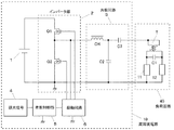
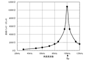
以下、本発明の第1の実施の形態の放電灯点灯装置を図1、図2、図3に基づいて説明する。図1は本実施の形態の回路図を示しており、図2はバランサTと、バランサTと各放電灯との接続経路間に接続された容量性素子C1との並列共振作用によってバランサの巻線間に生じる合成インピーダンスの周波数特性を示したものである。また図3(a)は4ftの直管蛍光灯(FHF32)を周囲温度25℃、および0℃で調光点灯した時のランプ電流とランプ電圧の実効値特性を示したものであり、図3(b)はその負性抵抗値特性、すなわち図3(a)で示したランプ電流とランプ電圧の実効値特性の傾きを示したものである。まず、図1に基づいて、放電灯点灯装置の構成を説明する。
本発明の実施の形態2を図5に基づいて説明する。図5はバランサTのインダクタンスを1.3mHとし、コンデンサC1の容量を変化させた時の、バランサTのインダクタンスとコンデンサC1の並列共振周波数foと、放電灯11、12の各々に流れる電流の電流差比率との関係を示したものである。点灯条件は、調光下限調光比=5%(インバータ発振周波数=100kHz)とし、また、低温時の放電灯特性ばらつきを考慮し、放電灯11、12は等価抵抗値が各々5kΩと10kΩの固定抵抗に置き換えた。なお、電流差比率は、放電灯11、12に流れる電流の平均値と一方の放電灯に流れる電流との差(絶対値)の前記平均電流値に対する比率を示している。
本発明の実施の形態3を図6に基づいて説明する。図6はバランサTのインダクタンスを1.3mHとし、コンデンサC1の容量を変化させた時の、バランサTのインダクタンスとコンデンサC1の並列共振周波数foと、放電灯11、12のうち、一方の放電灯が先に放電を開始した場合に他方の放電灯両端に発生する電圧との関係を示したものである。このときの等価回路を図7(a)に示す。点灯条件は、放電灯の始動時におけるインバータ発振周波数を想定し、インバータ発振周波数fstr=70kHzとした。
本発明の実施の形態4を図8に基づいて説明する。本実施の形態は、図1の直流カットコンデンサC3に代えて、図8のように2つの直流カットコンデンサC4,C5を容量を半分にして接続したものである。このような構成においても実施の形態1〜3と同様の動作及び効果を得ることができる。これはコンデンサC1の容量に対して直流カットコンデンサC4,C5の容量は充分に大きいため、バランサTを介する前に直流成分をカットしても、バランサTを介した後で直流成分をそれぞれカットしても同様の特性を表すことができるからである。
図13は本発明の放電灯点灯装置を搭載した照明器具の外観を一例として示している。図中、Rは反射板、S1,S2はランプ11のソケット、S3,S4はランプ12のソケットである。
2 インバータ部
3 共振回路
5 発振制御部
T バランサ
11 放電灯
12 放電灯
40 負荷回路
C1 コンデンサ
Claims (2)
- 直流電源に接続され、直流電圧を高周波電圧に変換するインバータ部と、このインバータ部の出力に接続され、少なくとも1つのインダクタとコンデンサを有する共振回路と、前記共振回路における共振用コンデンサの両端間にバランサを介して複数の放電灯が並列的に接続される負荷回路と、前記インバータ部の発振周波数を変化させることにより放電灯の始動、および調光制御をおこなう発振制御部を備える放電灯点灯装置において、前記バランサと各放電灯との接続経路間に容量性素子を接続し、前記バランサのインダクタンスと、前記容量性素子との共振作用によってバランサの巻線間に生じる調光下限点灯時の合成インピーダンスが全点灯時の合成インピーダンスの少なくとも7倍以上であり、
前記バランサのインダクタンスと、前記容量性素子との並列共振周波数foと、調光下限点灯時における前記インバータ部の発振周波数fdimの関係が0.8×fdim≦fo≦1.6×fdimであり、
前記並列共振周波数foと、放電灯の始動時における前記インバータ部の発振周波数fstrとの関係がfo≧1.3×fstrであり、
前記バランサは、複数の巻線を有するトランスで構成され、各巻線は単層整列巻により構成されることを特徴とする放電灯点灯装置。 - 請求項1に記載の放電灯点灯装置を備える照明器具。
Priority Applications (1)
| Application Number | Priority Date | Filing Date | Title |
|---|---|---|---|
| JP2007057470A JP5122838B2 (ja) | 2007-03-07 | 2007-03-07 | 放電灯点灯装置及び照明器具 |
Applications Claiming Priority (1)
| Application Number | Priority Date | Filing Date | Title |
|---|---|---|---|
| JP2007057470A JP5122838B2 (ja) | 2007-03-07 | 2007-03-07 | 放電灯点灯装置及び照明器具 |
Publications (2)
| Publication Number | Publication Date |
|---|---|
| JP2008218333A JP2008218333A (ja) | 2008-09-18 |
| JP5122838B2 true JP5122838B2 (ja) | 2013-01-16 |
Family
ID=39838117
Family Applications (1)
| Application Number | Title | Priority Date | Filing Date |
|---|---|---|---|
| JP2007057470A Expired - Fee Related JP5122838B2 (ja) | 2007-03-07 | 2007-03-07 | 放電灯点灯装置及び照明器具 |
Country Status (1)
| Country | Link |
|---|---|
| JP (1) | JP5122838B2 (ja) |
Families Citing this family (3)
| Publication number | Priority date | Publication date | Assignee | Title |
|---|---|---|---|---|
| JP2011233265A (ja) | 2010-04-23 | 2011-11-17 | Panasonic Electric Works Co Ltd | 放電灯点灯装置及びそれを用いた照明器具 |
| JP2011233266A (ja) | 2010-04-23 | 2011-11-17 | Panasonic Electric Works Co Ltd | 放電灯点灯装置及びそれを用いた照明器具 |
| CN104540310B (zh) * | 2015-01-15 | 2017-06-16 | 苏州市纽克斯照明有限公司 | 一种植物补光灯用镇流器的输出谐振变换器及其控制方法 |
Family Cites Families (6)
| Publication number | Priority date | Publication date | Assignee | Title |
|---|---|---|---|---|
| JPS61218099A (ja) * | 1985-03-25 | 1986-09-27 | 松下電工株式会社 | 放電灯調光装置 |
| JP3291852B2 (ja) * | 1993-07-27 | 2002-06-17 | 松下電工株式会社 | 放電灯点灯装置 |
| JPH1126174A (ja) * | 1997-07-07 | 1999-01-29 | Matsushita Electric Works Ltd | 放電灯点灯装置 |
| JP3832074B2 (ja) * | 1998-02-24 | 2006-10-11 | 松下電工株式会社 | 放電灯点灯装置 |
| JP2006040855A (ja) * | 2004-06-22 | 2006-02-09 | Matsushita Electric Works Ltd | 放電灯点灯装置、照明装置、及び照明システム |
| JP4475072B2 (ja) * | 2004-09-22 | 2010-06-09 | パナソニック電工株式会社 | 放電灯点灯装置およびそれを用いる照明器具 |
-
2007
- 2007-03-07 JP JP2007057470A patent/JP5122838B2/ja not_active Expired - Fee Related
Also Published As
| Publication number | Publication date |
|---|---|
| JP2008218333A (ja) | 2008-09-18 |
Similar Documents
| Publication | Publication Date | Title |
|---|---|---|
| US7109665B2 (en) | Three-way dimming CFL ballast | |
| US5466992A (en) | Inverter ballast circuit featuring current regulation over wide lamp load range | |
| US6069455A (en) | Ballast having a selectively resonant circuit | |
| KR20040073320A (ko) | 다등점등의 방전관용 인버터회로 및 면광원시스템 | |
| JP2006140055A (ja) | バックライトインバータ及びその駆動方法 | |
| US6919693B2 (en) | High-voltage transformer and discharge lamp driving apparatus | |
| JP3832074B2 (ja) | 放電灯点灯装置 | |
| JP5122839B2 (ja) | 放電灯点灯装置及び照明器具 | |
| JP2008218333A (ja) | 放電灯点灯装置及び照明器具 | |
| US6137234A (en) | Circuit arrangement | |
| JP2006012660A (ja) | 放電灯点灯回路 | |
| JP4966055B2 (ja) | 放電灯点灯装置及びこれを用いた照明装置、液晶表示装置 | |
| JP4645460B2 (ja) | 放電灯点灯装置及び照明器具 | |
| JP2006012659A (ja) | 放電灯点灯回路 | |
| JP2007200721A (ja) | 放電灯点灯装置及び照明器具 | |
| JP2907549B2 (ja) | 複数のガス放電ランプのためのドライバ回路 | |
| JP2010123522A (ja) | 無電極放電灯点灯装置及び照明器具 | |
| JP4140219B2 (ja) | 放電灯点灯装置 | |
| JP2002324689A (ja) | 放電灯点灯装置、及びこれを用いた照明器具 | |
| JP2006120349A (ja) | 放電灯点灯装置と照明器具及び照明システム | |
| JP2006049030A (ja) | 放電灯用点灯回路 | |
| KR20040058071A (ko) | 유전체 배리어 방전 램프 점등 장치 | |
| KR101558980B1 (ko) | 개선된 led 형광램프 및 이를 채용하는 등기구 | |
| JP2007087738A (ja) | 放電灯駆動装置 | |
| JP2009218178A (ja) | 放電灯点灯装置及び照明器具 |
Legal Events
| Date | Code | Title | Description |
|---|---|---|---|
| A621 | Written request for application examination |
Free format text: JAPANESE INTERMEDIATE CODE: A621 Effective date: 20090909 |
|
| A977 | Report on retrieval |
Free format text: JAPANESE INTERMEDIATE CODE: A971007 Effective date: 20111021 |
|
| A131 | Notification of reasons for refusal |
Free format text: JAPANESE INTERMEDIATE CODE: A131 Effective date: 20111101 |
|
| A521 | Written amendment |
Free format text: JAPANESE INTERMEDIATE CODE: A523 Effective date: 20111216 |
|
| RD04 | Notification of resignation of power of attorney |
Free format text: JAPANESE INTERMEDIATE CODE: A7424 Effective date: 20111219 |
|
| A521 | Written amendment |
Free format text: JAPANESE INTERMEDIATE CODE: A821 Effective date: 20111220 |
|
| RD02 | Notification of acceptance of power of attorney |
Free format text: JAPANESE INTERMEDIATE CODE: A7422 Effective date: 20111220 |
|
| A711 | Notification of change in applicant |
Free format text: JAPANESE INTERMEDIATE CODE: A712 Effective date: 20120112 |
|
| A02 | Decision of refusal |
Free format text: JAPANESE INTERMEDIATE CODE: A02 Effective date: 20120410 |
|
| A521 | Written amendment |
Free format text: JAPANESE INTERMEDIATE CODE: A523 Effective date: 20120710 |
|
| A911 | Transfer of reconsideration by examiner before appeal (zenchi) |
Free format text: JAPANESE INTERMEDIATE CODE: A911 Effective date: 20120717 |
|
| TRDD | Decision of grant or rejection written | ||
| A01 | Written decision to grant a patent or to grant a registration (utility model) |
Free format text: JAPANESE INTERMEDIATE CODE: A01 Effective date: 20121002 |
|
| A01 | Written decision to grant a patent or to grant a registration (utility model) |
Free format text: JAPANESE INTERMEDIATE CODE: A01 |
|
| A61 | First payment of annual fees (during grant procedure) |
Free format text: JAPANESE INTERMEDIATE CODE: A61 Effective date: 20121025 |
|
| FPAY | Renewal fee payment (event date is renewal date of database) |
Free format text: PAYMENT UNTIL: 20151102 Year of fee payment: 3 |
|
| R150 | Certificate of patent or registration of utility model |
Free format text: JAPANESE INTERMEDIATE CODE: R150 |
|
| LAPS | Cancellation because of no payment of annual fees |