JP5127326B2 - ガス活管遮断工法におけるストッパ装置 - Google Patents
ガス活管遮断工法におけるストッパ装置 Download PDFInfo
- Publication number
- JP5127326B2 JP5127326B2 JP2007177755A JP2007177755A JP5127326B2 JP 5127326 B2 JP5127326 B2 JP 5127326B2 JP 2007177755 A JP2007177755 A JP 2007177755A JP 2007177755 A JP2007177755 A JP 2007177755A JP 5127326 B2 JP5127326 B2 JP 5127326B2
- Authority
- JP
- Japan
- Prior art keywords
- stopper
- pipe
- gas
- stopper member
- support portion
- Prior art date
- Legal status (The legal status is an assumption and is not a legal conclusion. Google has not performed a legal analysis and makes no representation as to the accuracy of the status listed.)
- Expired - Fee Related
Links
Images


Landscapes
- Pipe Accessories (AREA)
Description
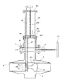
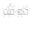
この挟持部6は、固定支持部61とスライド支持部62から構成されるが、固定支持部61はL字状であって内側のシリンダー部524の外周との間に十分な移動空間X4を形成し、この固定支持部61はシリンダー部524の外周の支持枠27側、即ち、ガス圧が加わる側に設けた突起部526に固定部材611(固定支持部61の)を固定的に設け、肉厚弾性リング部材7の片側面を挟持部材612で支持する。そして、ストッパ部材5の密着固定作業の稼働時には、スライド支持部62が肉厚弾性リング部材(肉厚ウレタンゴム)7のもう一方の片側面を押圧する方向(図中矢印)に移動させ、これらの部材により、肉厚弾性リング部材7が強力に押圧されることにより、肉厚弾性リング部材7は外周方向(図中矢印Z方向)に膨出し既設ガス管路Pの内壁に接圧するようになる。
なお、スライド支持部62を外気側にしたのは、外気側の方が管路側の通常7気圧に比べて低圧であるので、スライド支持部62の進退方向の移動がスムーズであるからである。
なお、本発明の特徴を損なうものでなければ、上記の実施例に限定させるものでないことは勿論である。
F…ゲートバルブ、F1…枠体、F2…開口部、F3…ゲート部、
F4…操作把持部、
G…継手部材、G1…上側継手部材、G2…下側継手部材、
G3,G4…開口、G5…作業開口部、G6…フランジ部材、
g1〜g4 …溶接箇所、P…既設ガス管路、Z…工事区間、
X1…シリンダー空間、X2,X3,X4…移動空間、
Y1…リング部材の平坦状態、Y2…リング部材の膨出状態
1…ストッパ装置
2…ストッパ挿入部材、21…収納部、211…下端面、212…Oリング、
22…膨出縁、23…天井部、24…支持筒、241…固定ボルト、
25a…下部ベース部、25b…上部ベース部、
26、26a,26b…油圧パイプ、27…支持枠、
271…ガイド部材、272…ストッパ部材固定ボルト、
3…クランプ、31…ボルト、
5…ストッパ部材、
51…基礎部、511a,512…配管、511b…大配管、
513…外周部、514…Oリング、515…外周スライド部、
52…進退部、521…内周スライド部、522…Oリング、523…内壁部、
524…シリンダー部、524a…外周、524b…先端部、
525…前面蓋部、525a…側端部、526…突起部、
6…挟持部、61…固定支持部、611…固定部材、612…挟持部材、
62…スライド支持部、621…スライド部材、621a…側部、622…挟持部材、
623…ボルト、624…筒状内周壁、63…導入孔
7…肉厚弾性リング部材
Claims (2)
- 既設管路の一部にストッパ部材を挿入する穿孔を設けたガス管路に用いるストッパ装置であって、
前記ストッパ装置はストッパ部材と、一端に前記ストッパ部材が取付けられ、前記ストッパ部材を前記穿孔から管路内へ挿入可能なストッパ挿入部材と、からなり、
前記ストッパ部材は、
一端が前記ストッパ挿入部材に固定された基礎部と、
前記基礎部の外周に設けられ、前記基礎部に対して管路の軸方向に摺動可能に設けられた進退部と、
管路内壁に接する肉厚弾性リング部材と、
前記進退部の外周に設けられた固定支持部及び前記進退部に対して摺動可能に設けられたスライド支持部を有し、前記固定支持部と前記スライド支持部が前記肉厚弾性リング部材を挟持する挟持部と、
滑動押圧機構と、
を備え、
該滑動押圧機構は、前記ストッパ部材が前記穿孔から挿入された状態で、前記進退部を所定の管路内壁に到達させ、前記挟持部の前記スライド支持部を、前記肉厚弾性リング部材を押圧する方向に移動させることを特徴とするガス活管遮断工法におけるストッパ装置。 - 前記進退部及び前記スライド支持部の移動のための前記滑動押圧機構は、油圧回路を用いたことを特徴とする請求項1に記載のガス活管遮断工法におけるストッパ装置。
Priority Applications (1)
| Application Number | Priority Date | Filing Date | Title |
|---|---|---|---|
| JP2007177755A JP5127326B2 (ja) | 2007-07-05 | 2007-07-05 | ガス活管遮断工法におけるストッパ装置 |
Applications Claiming Priority (1)
| Application Number | Priority Date | Filing Date | Title |
|---|---|---|---|
| JP2007177755A JP5127326B2 (ja) | 2007-07-05 | 2007-07-05 | ガス活管遮断工法におけるストッパ装置 |
Publications (2)
| Publication Number | Publication Date |
|---|---|
| JP2009014125A JP2009014125A (ja) | 2009-01-22 |
| JP5127326B2 true JP5127326B2 (ja) | 2013-01-23 |
Family
ID=40355261
Family Applications (1)
| Application Number | Title | Priority Date | Filing Date |
|---|---|---|---|
| JP2007177755A Expired - Fee Related JP5127326B2 (ja) | 2007-07-05 | 2007-07-05 | ガス活管遮断工法におけるストッパ装置 |
Country Status (1)
| Country | Link |
|---|---|
| JP (1) | JP5127326B2 (ja) |
Families Citing this family (2)
| Publication number | Priority date | Publication date | Assignee | Title |
|---|---|---|---|---|
| KR100948851B1 (ko) * | 2008-06-11 | 2010-03-19 | 경남에너지 주식회사 | 분기 차단 장치 |
| JP5769480B2 (ja) * | 2011-04-14 | 2015-08-26 | コスモ工機株式会社 | バイパス装置 |
Family Cites Families (4)
| Publication number | Priority date | Publication date | Assignee | Title |
|---|---|---|---|---|
| US4422477A (en) * | 1981-02-27 | 1983-12-27 | Hughes Tool Company | Pressure energized pipeline plug |
| JPH0488297A (ja) * | 1990-07-31 | 1992-03-23 | Osaka Gas Co Ltd | 配管の遮断方法 |
| JPH04194491A (ja) * | 1990-11-28 | 1992-07-14 | Okamoto:Kk | 不断水工法における管路の止水方法 |
| IES20020089A2 (en) * | 2002-02-08 | 2003-08-20 | Carsphairn Ltd | An improved pipeline isolation tool |
-
2007
- 2007-07-05 JP JP2007177755A patent/JP5127326B2/ja not_active Expired - Fee Related
Also Published As
| Publication number | Publication date |
|---|---|
| JP2009014125A (ja) | 2009-01-22 |
Similar Documents
| Publication | Publication Date | Title |
|---|---|---|
| CN105190145B (zh) | 分水栓形成方法及使用同方法的分水栓安装用夹具 | |
| US3799182A (en) | Add-on stopper valve for existing piping | |
| US7281543B2 (en) | Apparatus, systems and methods for plugging a high temperature pipe | |
| RU2717177C2 (ru) | Инструмент для работы на стенке трубопровода и соответствующий способ | |
| DK1700061T3 (da) | Indretning og fremgangsmåde til reparation af rør under anvendelse af hydrofile tætninger | |
| JP5127326B2 (ja) | ガス活管遮断工法におけるストッパ装置 | |
| JP2023178374A (ja) | 制流弁の開弁方法 | |
| CN113048322A (zh) | 一种非开挖的管道修复装置及其管道修复方法 | |
| JP2023024545A (ja) | 流体管の切除方法 | |
| US9052050B2 (en) | Valve device for the assembly in in-service pipelines and the assembly procedure of said device | |
| KR100964629B1 (ko) | 유체관 라인 스토핑 장치 | |
| KR102083849B1 (ko) | 배관 용접용 파이프 내부 퍼징장치 | |
| CN101193722A (zh) | 凸轮辅助的、楔件驱动的、金属对金属密封的、堵塞和排放插接工具 | |
| JP2025083510A (ja) | 制流弁 | |
| JPS6326489A (ja) | 水道管路の不断水分岐施工方法及びその装置 | |
| KR20170101348A (ko) | 부단수 차단 디스크형 헤드 | |
| KR101535458B1 (ko) | 배관용 분기티 제어장치 | |
| JP2011133075A (ja) | 分岐継手を通してガス管に穿孔後のシール方法及び装置 | |
| US7753068B2 (en) | Diversion under load conditions in distribution systems | |
| JP4642521B2 (ja) | 既設流体管の不断水制水体設置装置 | |
| JP2825951B2 (ja) | 配管の工事方法 | |
| JP4642522B2 (ja) | 既設流体管の不断水制水体設置装置 | |
| JP7658835B2 (ja) | 制流弁 | |
| JP2002031289A (ja) | 配管敷設工法 | |
| JP4519580B2 (ja) | 既設流体管の不断水流路形成装置 |
Legal Events
| Date | Code | Title | Description |
|---|---|---|---|
| A621 | Written request for application examination |
Free format text: JAPANESE INTERMEDIATE CODE: A621 Effective date: 20100630 |
|
| A131 | Notification of reasons for refusal |
Free format text: JAPANESE INTERMEDIATE CODE: A131 Effective date: 20120703 |
|
| A521 | Request for written amendment filed |
Free format text: JAPANESE INTERMEDIATE CODE: A523 Effective date: 20120829 |
|
| TRDD | Decision of grant or rejection written | ||
| A01 | Written decision to grant a patent or to grant a registration (utility model) |
Free format text: JAPANESE INTERMEDIATE CODE: A01 Effective date: 20121002 |
|
| A01 | Written decision to grant a patent or to grant a registration (utility model) |
Free format text: JAPANESE INTERMEDIATE CODE: A01 |
|
| A61 | First payment of annual fees (during grant procedure) |
Free format text: JAPANESE INTERMEDIATE CODE: A61 Effective date: 20121030 |
|
| R150 | Certificate of patent or registration of utility model |
Ref document number: 5127326 Country of ref document: JP Free format text: JAPANESE INTERMEDIATE CODE: R150 Free format text: JAPANESE INTERMEDIATE CODE: R150 |
|
| FPAY | Renewal fee payment (event date is renewal date of database) |
Free format text: PAYMENT UNTIL: 20151109 Year of fee payment: 3 |
|
| R250 | Receipt of annual fees |
Free format text: JAPANESE INTERMEDIATE CODE: R250 |
|
| R250 | Receipt of annual fees |
Free format text: JAPANESE INTERMEDIATE CODE: R250 |
|
| R250 | Receipt of annual fees |
Free format text: JAPANESE INTERMEDIATE CODE: R250 |
|
| LAPS | Cancellation because of no payment of annual fees |