JP5128032B2 - Operation method of fuel cell - Google Patents
Operation method of fuel cell Download PDFInfo
- Publication number
- JP5128032B2 JP5128032B2 JP2001203939A JP2001203939A JP5128032B2 JP 5128032 B2 JP5128032 B2 JP 5128032B2 JP 2001203939 A JP2001203939 A JP 2001203939A JP 2001203939 A JP2001203939 A JP 2001203939A JP 5128032 B2 JP5128032 B2 JP 5128032B2
- Authority
- JP
- Japan
- Prior art keywords
- fuel cell
- hydrogen
- pressure
- operating pressure
- amount
- Prior art date
- Legal status (The legal status is an assumption and is not a legal conclusion. Google has not performed a legal analysis and makes no representation as to the accuracy of the status listed.)
- Expired - Fee Related
Links
Images




Classifications
-
- H—ELECTRICITY
- H01—ELECTRIC ELEMENTS
- H01M—PROCESSES OR MEANS, e.g. BATTERIES, FOR THE DIRECT CONVERSION OF CHEMICAL ENERGY INTO ELECTRICAL ENERGY
- H01M8/00—Fuel cells; Manufacture thereof
- H01M8/04—Auxiliary arrangements, e.g. for control of pressure or for circulation of fluids
- H01M8/04298—Processes for controlling fuel cells or fuel cell systems
-
- H—ELECTRICITY
- H01—ELECTRIC ELEMENTS
- H01M—PROCESSES OR MEANS, e.g. BATTERIES, FOR THE DIRECT CONVERSION OF CHEMICAL ENERGY INTO ELECTRICAL ENERGY
- H01M8/00—Fuel cells; Manufacture thereof
- H01M8/04—Auxiliary arrangements, e.g. for control of pressure or for circulation of fluids
- H01M8/04082—Arrangements for control of reactant parameters, e.g. pressure or concentration
- H01M8/04089—Arrangements for control of reactant parameters, e.g. pressure or concentration of gaseous reactants
-
- H—ELECTRICITY
- H01—ELECTRIC ELEMENTS
- H01M—PROCESSES OR MEANS, e.g. BATTERIES, FOR THE DIRECT CONVERSION OF CHEMICAL ENERGY INTO ELECTRICAL ENERGY
- H01M8/00—Fuel cells; Manufacture thereof
- H01M8/24—Grouping of fuel cells, e.g. stacking of fuel cells
- H01M8/241—Grouping of fuel cells, e.g. stacking of fuel cells with solid or matrix-supported electrolytes
-
- H—ELECTRICITY
- H01—ELECTRIC ELEMENTS
- H01M—PROCESSES OR MEANS, e.g. BATTERIES, FOR THE DIRECT CONVERSION OF CHEMICAL ENERGY INTO ELECTRICAL ENERGY
- H01M8/00—Fuel cells; Manufacture thereof
- H01M8/24—Grouping of fuel cells, e.g. stacking of fuel cells
- H01M8/2457—Grouping of fuel cells, e.g. stacking of fuel cells with both reactants being gaseous or vaporised
-
- Y—GENERAL TAGGING OF NEW TECHNOLOGICAL DEVELOPMENTS; GENERAL TAGGING OF CROSS-SECTIONAL TECHNOLOGIES SPANNING OVER SEVERAL SECTIONS OF THE IPC; TECHNICAL SUBJECTS COVERED BY FORMER USPC CROSS-REFERENCE ART COLLECTIONS [XRACs] AND DIGESTS
- Y02—TECHNOLOGIES OR APPLICATIONS FOR MITIGATION OR ADAPTATION AGAINST CLIMATE CHANGE
- Y02E—REDUCTION OF GREENHOUSE GAS [GHG] EMISSIONS, RELATED TO ENERGY GENERATION, TRANSMISSION OR DISTRIBUTION
- Y02E60/00—Enabling technologies; Technologies with a potential or indirect contribution to GHG emissions mitigation
- Y02E60/30—Hydrogen technology
- Y02E60/50—Fuel cells
Landscapes
- Life Sciences & Earth Sciences (AREA)
- Engineering & Computer Science (AREA)
- Manufacturing & Machinery (AREA)
- Sustainable Development (AREA)
- Sustainable Energy (AREA)
- Chemical & Material Sciences (AREA)
- Chemical Kinetics & Catalysis (AREA)
- Electrochemistry (AREA)
- General Chemical & Material Sciences (AREA)
- Fuel Cell (AREA)
Description
【0001】
【発明の属する技術分野】
この発明は、水素ガスと酸化剤ガスを反応ガスとして発電する燃料電池の運転方法に関し、特に、水素漏れに対する安全管理に優れた燃料電池の運転方法に関するものである。
【0002】
【従来の技術】
燃料電池自動車等に搭載される燃料電池には、例えば固体ポリマーイオン交換膜等からなる固体高分子電解質膜をアノードとカソードとで両側から挟み込んで形成されたセルを複数積層して構成されたスタックからなり、燃料ガスとして水素ガスが供給される水素極と、酸化剤ガスとして酸素を含む空気が供給される空気極とを備えたものがある。この燃料電池においては、アノードで触媒反応により発生した水素イオンが、固体高分子電解質膜を通過してカソードまで移動して、カソードで酸素と電気化学反応を起こして発電する。
【0003】
ところで、水素ガスは可燃性ガスであるため、大気中への漏洩には十分な注意が必要であり、一般に水素を取り扱う場所では、安全管理上、水素濃度をモニターして、検出した水素濃度の大きさに応じて必要な措置を施すようにしており、水素ガスを燃料とする燃料電池も例外ではない。その一方で、水素は透過性の高い物質であるため完全に遮断するのは極めて難しく、特に、前述した固体高分子電解質膜型の燃料電池は積層構造をなすため、燃料電池から水素が漏出するのを完全に遮断するのは難しい。
【0004】
そこで、従来は、燃料電池の近傍に水素濃度を検出する水素センサを設置し、水素センサが所定水素濃度以上を検出した場合には、警報を発したり、燃料電池の運転を停止させたりしている。
また、例えば、特開平8−31436号公報に開示されているように、燃料電池を換気可能なボックスに収納し、ボックス内に水素濃度を検出する水素センサを設置してボックス内の水素濃度を常時監視し、水素センサで検出された水素濃度が所定値を越えたときには、換気ファンを運転して強制換気し、ボックス内の水素濃度を低減するようにしたものもある。
【0005】
【発明が解決しようとする課題】
しかしながら、従来のように水素センサで所定水素濃度を検知したときに警報や運転停止を行うシステムの場合には、予見性がなく緊急停止してしまうときがある。燃料電池自動車の場合に、このように燃料電池の運転が緊急停止してしまうと、修理をする場所まで移動することができなくなるという問題があった。
また、特開平8−31436号公報に開示されたように、水素センサで所定水素濃度を検知したときに換気ファンを運転してボックス内を強制換気するシステムの場合には、水素の漏洩量を抑制するわけではないので、その後も水素の漏洩量が増大し続ける虞があった。
【0006】
そこで、この発明は、燃料電池からの水素漏れ量は燃料電池の作動圧力(すなわち、反応ガスの供給圧力)と相関があり、作動圧力が高いほど水素漏れ量が多くなるという特性を利用して、燃料電池からの水素漏れ量が所定値を越えないように作動圧力を制限する燃料電池の運転方法を提供するものである。
【0007】
【課題を解決するための手段】
上記課題を解決するために、請求項1に記載した発明は、水素ガスと酸化剤ガスを反応ガスとして発電する燃料電池(例えば、後述する実施の形態における燃料電池11)を、酸化剤ガス圧力を基準として水素ガス圧力を調整し、燃料極と空気極との極間差圧を所定範囲内としつつ、要求発電状態に応じた水素ガス圧力と酸化剤ガス圧力とのうち少なくとも一方の作動圧力にて運転する燃料電池の運転方法において、前記燃料電池の周辺に水素濃度を検出して信号を出力する水素センサ(例えば、後述する実施の形態における水素センサ54)を設け、該水素センサの検出値から得られる現在の作動圧力(例えば、実施形態における作動圧力Pn)での水素漏れ量(例えば、実施形態における水素濃度Hn)と、前記燃料電池における作動圧力に対する水素漏れ量の変化率と、に基づいて、水素漏れ量が所定値(例えば、後述する実施の形態における許容水素漏れ量Hlim)を超えない作動圧力(例えば、後述する実施の形態における許容作動圧力Plim)を予測し、該作動圧力以下に作動圧力(例えば、後述する実施の形態における空気供給圧力)を制限することを特徴とする。
【0008】
燃料電池の周辺の換気量が一定のときには、燃料電池からの水素漏れ量と燃料電池周辺の水素濃度との間には相関がある。したがって、水素センサの検出値に基づいて燃料電池からの水素漏れ量を推定することができる。また、燃料電池からの水素漏れ量は燃料電池の作動圧力(すなわち、反応ガスの供給圧力)に依存し、作動圧力が高いほど水素漏れ量が多くなるという特性を有している。したがって、水素センサの検出値に基づいて、前記燃料電池からの水素漏れ量が所定値を越えないように前記作動圧力を制限して燃料電池の運転を制御することが可能となる。
また、燃料電池の周辺の換気量が一定のときには燃料電池からの水素漏れ量と燃料電池周辺の水素濃度との間には相関があり、燃料電池からの水素漏れ量は燃料電池の作動圧力(すなわち、反応ガスの供給圧力)に依存するので、水素センサで検出した現在の水素濃度と現在の燃料電池の作動圧力から、水素漏れ量が前記所定値未満となる作動圧力を予測することができ、該作動圧力以下に作動圧力を制限して燃料電池の運転を制御することが可能となる。
【0009】
請求項2に記載した発明は、請求項1に記載の発明において、前記現在の作動圧力での水素漏れ量が予め設定された最大水素漏れ量(例えば、実施形態における最大水素濃度Hmax)よりも大きい場合には、前記燃料電池を停止させることを特徴とする。
【0010】
【発明の実施の形態】
以下、この発明に係る燃料電池の運転方法の一実施の形態を図1から図7の図面を参照して説明する。なお、この実施の形態は、燃料電池自動車に搭載された燃料電池に適用した態様である。
【0011】
図1は燃料電池自動車の概略構成図である。
燃料電池自動車1は、燃料電池11と、蓄電装置、例えばキャパシタ12とから構成されたハイブリッド型の電源装置を備えており、これらの電源装置から電力が供給される走行用モータ13の駆動力は、オートマチックトランスミッション或いはマニュアルトランスミッションよりなるトランスミッションT/Mを介して駆動輪Wに伝達される。
また、車両の減速時に駆動輪W側から走行用モータ13側に駆動力が伝達されると、走行用モータ13は発電機として機能していわゆる回生制動力を発生し、車体の運動エネルギーを電気エネルギーとして回収する。
【0012】
燃料電池11は、例えば固体ポリマーイオン交換膜等からなる固体高分子電解質膜をアノードとカソードとで両側から挟み込んで形成されたセルを複数積層して構成されたスタックからなり、燃料ガスとして水素ガスが供給される水素極と、酸化剤ガスとして酸素を含む空気が供給される空気極とを備えている。そして、アノードで触媒反応により発生した水素イオンが、固体高分子電解質膜を通過してカソードまで移動して、カソードで酸素と電気化学反応を起こして発電するようになっている。
【0013】
燃料電池11の空気極には、酸化剤供給部をなすエアコンプレッサ21から空気が供給される空気供給口11aと、空気極内の空気等を外部に排出するための空気排出口11bが設けられている。一方、水素極には、燃料供給部をなす水素タンク31から水素ガスが供給される水素供給口11cと、水素極内の水素ガス等を外部に排出するための水素排出口11dが設けられている。
【0014】
エアコンプレッサ21は、例えば車両の外部から空気を取り込んで断熱圧縮して、この空気を、反応ガスとして燃料電池11の空気極側に供給すると共に、圧力信号として後述する燃料供給制御弁32およびエゼクタバイパス制御弁35に供給する。
エアコンプレッサ21にて圧縮昇温された空気は、冷却器22に供給可能とされており、例えば燃料電池11の運転状態に応じて、冷却器22にて所定温度まで冷却された空気は、カソード加湿器24および燃料供給制御弁32およびエゼクタバイパス制御弁35に供給される。
【0015】
また、エアコンプレッサ21と、カソード加湿器24および燃料供給制御弁32およびエゼクタバイパス制御弁35とを接続する流路には、冷却器22および、例えば冷却器22の下流側に設けられた冷却器バイパス制御弁23を迂回する冷却器バイパス流路22aが設けられている。
すなわち、燃料電池11の運転状態に応じて、冷却器バイパス制御弁23を閉弁することによって、エアコンプレッサ21にて圧縮昇温された空気を、冷却すること無しに燃料電池11および燃料供給制御弁32およびエゼクタバイパス制御弁35へ供給することができるようにされている。
【0016】
カソード加湿器24は、例えば中空糸膜等の水透過膜を備えて構成されており、燃料電池11の空気排出口11bから排出される排出空気を、反応ガスとして供給される空気に対する加湿ガスとして利用している。すなわち、水透過膜を介して空気と排出空気とを接触させると、排出空気に含まれる水分(特に、水蒸気)は水透過膜の膜穴を透過した後に水蒸気として空気に供給される。
そして、加湿された空気は燃料電池11に供給され、燃料電池11の固体高分子電解質膜のイオン導電性が所定の状態に確保されている。
なお、後述するように、燃料電池11の空気排出口11bから排出された排出空気は、順次、アノード加湿器37、カソード加湿器24へ加湿ガスとして供給され、カソード加湿器24から排出された排出空気は背圧制御弁25を介して車外に排出されるようになっている。
【0017】
背圧制御弁25は、燃料電池11の運転状態に応じて、ECU44によって開閉動作が制御されており、ECU44から入力される制御信号に応じた弁開度に設定されることで、燃料電池11内に反応ガスとして供給される空気の圧力(空気供給圧力)が所定の圧力となるように制御される。なお、空気供給圧力は、燃料電池11の発電電流が大きいほど大きくなるように制御される。
【0018】
燃料電池11に対する燃料としての水素ガスは、例えば高圧の水素タンク31から燃料供給制御弁32へ供給される。
燃料供給制御弁32は、例えば空気式の比例圧力制御弁をなし、エアコンプレッサ21から供給される空気の圧力を信号圧として、燃料供給制御弁32を通過した水素ガスが燃料供給制御弁32の出口で有する圧力が、信号圧に応じた所定範囲の圧力となるように制御する。
【0019】
燃料供給制御弁32を通過した水素ガスは熱交換器33に供給されている。この熱交換器33において、燃料電池11の運転状態に応じて、例えば冷却材との熱交換反応等によって所定の温度に設定された水素ガスは、順次、エゼクタ34あるいはエゼクタバイパス制御弁35、アノード加湿器36を介して水素供給口11cから燃料電池11の水素極に供給される。
【0020】
さらに、燃料電池11の水素排出口11dから排出された未反応の排出ガスは、貯溜タンク37を通じてエゼクタ34へと導入されており、熱交換器33から供給された水素ガスと、燃料電池11から排出された排出ガスとが混合されて燃料電池11に再び供給されている。
エゼクタ34は、内部を流通する高速の水素ガス流の近傍に発生する負圧によって、副流とされる燃料電池11からの排出ガスを吸い込み、この排出ガスを熱交換器33を介して供給される水素ガスと混合して燃料電池11へ再度供給することで、燃料電池11から排出された排出ガスを循環させている。
【0021】
また、熱交換器33とアノード加湿器36とを接続する流路には、エゼクタ34を迂回するエゼクタバイパス流路34aが設けられている。
ここで、エゼクタバイパス流路34aには、例えば空気式の比例圧力制御弁をなすエゼクタバイパス制御弁35がエゼクタ34に対して並列配置されており、エアコンプレッサ21から供給される空気の圧力を信号圧として、エゼクタバイパス制御弁35を通過した水素ガスがエゼクタバイパス制御弁35の出口で有する圧力つまり水素供給圧力が、信号圧に応じた所定範囲の圧力となるように制御される。
【0022】
すなわち、酸化剤ガスとしての空気の圧力を基準圧力として、燃料供給制御弁32およびエゼクタバイパス制御弁35での圧力流量制御によって、エゼクタ34を通過する水素ガスの圧力流量特性が所定の状態となるように制御され、燃料電池11の固体高分子電解質膜に対する酸化剤の圧力(空気供給圧力)と、燃料の圧力(水素供給圧力)との差、つまり燃料極と空気極との極間差圧が所定圧力差の範囲内になるように制御される。
つまり、燃料電池11に供給される空気供給圧力および水素供給圧力(すなわち、燃料電池11の作動圧力)は、燃料電池11の運転状態に応じて制御され、燃料電池11の発電電流が大きくなるほど燃料電池11の作動圧力が大きくなるように制御される。
【0023】
アノード加湿器36は、例えば中空糸膜等の水透過膜を備えて構成されており、燃料電池11の空気排出口11bから排出される排出空気を、水素ガスに対する加湿ガスとして利用している。すなわち、水透過膜を介して水素ガスと排出空気とを接触させると、排出空気に含まれる水分(特に、水蒸気)は水透過膜の膜穴を透過した後に水蒸気として水素ガスに供給される。
そして、加湿された水素ガスは燃料電池11に供給され、燃料電池11の固体高分子電解質膜のイオン導電性が所定の状態に確保されている。
【0024】
貯溜タンク37は、燃料電池11の水素排出口11dから排出された排出ガスに対して気液分離を行い、排出ガス中に含まれる液体状の水分を分離して貯溜する。
排出制御弁38は、燃料電池11の運転状態に応じて、ECU44によって開閉動作が制御されており、例えば貯溜タンク37にて分離された排出ガス中の過剰な水分(主に液体水)等を車外に排出する。
【0025】
燃料電池11から取り出される発電電流は電流制御器41に入力されており、この電流制御器41には蓄電装置をなす、例えば電気二重層コンデンサや電解コンデンサ等からなるキャパシタ12が接続されている。
そして、燃料電池11とキャパシタ12は、電流制御器41および出力制御器42を介して、電気的負荷である走行用モータ13、および、エアコンプレッサ21を駆動するモータ43等に対して並列に接続されている。
【0026】
電流制御器41は、例えばDC−DCチョッパ等を備えて構成されており、後述するように、ECU44から出力される目標発電電流IFCつまり燃料電池11に対する発電指令に基づいて、燃料電池11から取り出される発電電流の電流値を制御する。
【0027】
出力制御器42は、例えばIGBT等のスイッチング素子から構成された走行モータ用およびエアコンプレッサモータ用のPWMインバータをそれぞれ備えており、後述するように、ECU44から出力される走行用モータ13に対するトルク指令やエアコンプレッサ21に対する回転数指令等に基づき、電流制御器41を介して燃料電池11およびキャパシタ12から出力される直流電力を3相交流電力に変換して、走行用モータ13およびエアコンプレッサ21を駆動するモータ43へ供給する。
【0028】
なお、走行用モータ13およびモータ43は、例えば界磁として永久磁石を利用する永久磁石式の3相交流同期モータとされており、出力制御器42から供給される3相交流電力により駆動制御される。
ECU44は、例えば、蓄電装置をなすキャパシタ12から出力される出力電流および端子電圧および温度の信号に基づいてキャパシタ12の残容量を算出し、走行用モータ13やモータ43等の負荷への電力供給を制御する。
【0029】
さらに、ECU44は、出力制御器42に具備された前記PWMインバータの電力変換動作を制御しており、例えば走行用モータ13に対しては、運転者によるアクセルペダルの踏み込み操作量等に関するアクセル開度ACの信号に基づいて、要求されるモータ出力を算出する。そして、このモータ出力指令を出力制御器42に入力することで、モータ出力指令に応じたパルス幅変調信号が走行モータ用PWMインバータに入力され、要求されるモータ出力を発生させるための各相電流が走行用モータ13の各相へと出力される。
【0030】
また、ECU44は、燃料電池11を運転するために必要な補機類の電気負荷を算出し、この電気負荷と前記走行用モータ13に要求されるモータ出力に基づいて、電流制御器41にて燃料電池11から取り出す発電電流に対する目標発電電流IFCを算出し電流制御器41に入力する。
さらに、ECU44は、目標発電電流に基づいて、反応ガスの流量に関する要求値として、例えばエアコンプレッサ21の回転数Nを算出し、反応ガスの圧力に関する要求値として、例えば背圧制御弁25の弁開度θを算出する。そして、この回転数Nが出力制御器42に入力されることで、回転数Nに応じた各相電流がモータ43の各相へと出力される。また、算出された弁開度θが背圧制御弁25に入力されることで、背圧制御弁25の弁開度が制御される。
【0031】
そして、反応ガスの流量および圧力に対する各要求値と、実際に燃料電池11に供給される反応ガスの流量および圧力との各偏差がゼロとなるように、エアコンプレッサ21の回転数Nおよび背圧制御弁25の弁開度θのフィードバック制御を行う。
【0032】
このため、ECU44には、アクセル開度センサ14から出力される例えば運転者によるアクセルペダルの踏み込み操作量等に関するアクセル開度ACの検出信号と、例えばエアコンプレッサ21から供給される空気の流量(質量流量)を検出するガス量センサ46から出力される流量検出値QNの信号と、例えば燃料電池11の空気極側に供給される空気の圧力を検出する圧力センサ47から出力される圧力検出値PNの信号とが入力される。
なお、ガス量センサ46は、エアコンプレッサ21の空気排出口21a近傍に設けられ、圧力センサ47は、燃料電池11の空気供給口11a近傍に設けられている。
【0033】
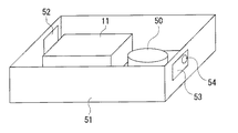
また、この燃料電池自動車1においては、図2に示すように、燃料電池11と水素供給系デバイス群50は密閉された箱(以下、FCボックスという)51に収納されている。ここで、水素供給系デバイス群50には、燃料供給制御弁32,熱交換器33,エゼクタ34,エゼクタバイパス制御弁35,アノード加湿器36,およびこれらを接続する配管類が含まれる。
【0034】
FCボックス51は、燃料電池11からの水素漏れを管理するために設けられたものであり、そのために、FCボックス51には、一定流量で換気が行われるように換気入口52と換気出口53が設けられるとともに、換気出口53の近傍に水素濃度を検出する水素センサ54が設置されていて、水素センサ54から出力される水素濃度検出値の信号はECU44に入力される。なお、水素センサ54の設置位置は換気出口53の近傍に限るものではなく、FCボックス51内に漏洩した水素ガスが流れるであろう位置に設置されていればよく、例えば燃料電池11の近傍に設置することも可能である。また、FCボックス51は容量が小さい方が水素漏れ検出精度が高くなるので好ましい。
【0035】
次に、この燃料電池自動車1において、水素漏れ管理を考慮した燃料電池11の運転制御原理について説明する。
前述したように、水素ガスを燃料とする固体高分子電解質膜型の燃料電池11においては、水素の透過性が高いことと、および積層構造という燃料電池11の構造上から、燃料電池11に供給された水素が燃料電池11の構成部材(例えば、固体高分子電解質膜やその両側に配置されるセパレータ等)を透過してきてFCボックス51内に漏れたりする。これは、固体高分子電解質膜型の燃料電池11では、欠陥が全くない新品の燃料電池11であっても避けられない現象である。
【0036】
したがって、たとえ欠陥のない新品の燃料電池11を使用している場合であっても、FCボックス51内を換気しないとFCボックス51内の水素濃度が増大していくこととなる。そのため、この実施の形態では、換気入口52からFCボックス51内に一定流量で換気を導入し、換気出口53から排出している。
このように、FCボックス51を一定流量で換気した場合、燃料電池11からの水素漏れ量とFCボックス51内の水素濃度との間には、図3に示すような一次関数的な関係が成立する。したがって、水素センサ54により検出したFCボックス51内の水素濃度に基づいて、燃料電池11からの水素漏れ量を推定することができる。
【0037】
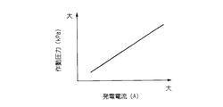
一方、燃料電池11は、前述したように、燃料電池11の要求発電状態(アクセル開度に応じた要求発電電流等)に応じて作動圧力を変えて運転している。図4は、燃料電池11の発電電流と作動圧力との関係の一例を示したものであり、発電電流が大きいほど作動圧力が大きくなるように制御している。また、作動圧力には最大作動圧力Pmaxが設定されており、作動圧力はこの最大作動圧力Pmax以下において制御されることとなる。
【0038】
また、燃料電池11からの水素の漏れ量は作動圧力に依存することが経験的にわかっている。図5は、燃料電池11の作動圧力と水素漏れ量との関係を実験的に求めた実験結果の一例を示し、図中実線は、欠陥が全くない新品の燃料電池11の平均的な水素漏れ特性を示している。すなわち、この例の場合では、作動圧力が大きくなればなるほど、水素漏れ量が一次関数的に増大していく。また、実験によれば、同一仕様の燃料電池11ではあるが、燃料電池11の固体ばらつきあるいは経時劣化により前記新品の燃料電池11の平均的な水素漏れ特性と一致しない燃料電池11の場合にも、作動圧力の増減に対する水素漏れ量の増減の割合(換言すれば、図5における水素漏れ特性線の傾き)は同じであることが判明している。
【0039】
なお、燃料電池11からの水素漏れ量は、正確に言えば燃料電池11への水素供給圧力に依存するのであるが、前述したように、この燃料電池1では、水素供給圧力は空気供給圧力を基準圧力として制御されるので、燃料電池11からの水素漏れ量は燃料電池11への空気供給圧力に依存すると言うことができる。水素供給圧力も空気供給圧力も燃料電池11の作動圧力には変わりなく、燃料電池11からの水素漏れ量は作動圧力に依存する。
ただし、この実施の形態の燃料電池11では、発電電流を制御するためのパラメータとして燃料電池11への空気供給量と空気供給圧力を用いており、これらパラメータをフィードバック制御するためにガス量センサ46で空気供給量を検出し、圧力センサ47で空気供給圧力を検出しているので、この実施の形態では水素漏れ量との関係において空気供給圧力を作動圧力として用いることとした。
【0040】
以上のことから、同一仕様の燃料電池11においては、水素センサ54で検出した現在のFCボックス51内の水素濃度Hnと、圧力センサ47で検出した現在の作動圧力Pnがわかれば、図5に示す水素漏れ特性に基づいて、この燃料電池11を最大作動圧力Pmaxで運転したときの水素漏れ量Hinfを予測することができ、また、所定の水素漏れ量Hlimとなるときの作動圧力Plimを推定することができる。ここで、前記所定の水素漏れ量(以下、許容水素漏れ量という)Hlimを最大水素漏れ量Hmaxよりも小さい値に設定し、これに対応する作動圧力(以下、許容作動圧力という)Plim以下で燃料電池11を運転するように制御すれば、燃料電池11からの水素漏れ量を許容水素漏れ量Hlim以下に抑制しながら、燃料電池11を運転することが可能になる。
【0041】
なお、水素漏れ量は水素センサ54で検出される水素濃度に基づいて推定することから、図5に示す水素漏れ特性図における縦軸の水素漏れ量は、これに対応する水素濃度に置き換えることが可能である。そこで、以下の説明の都合上、図5における縦軸に水素濃度を併記した。
【0042】
また、発電電流と作動圧力は図4に示すような関係があるので、許容作動圧力Plimに対応して発電電流(以下、許容発電電流という)Ilimを決定することができる。したがって、作動圧力を許容作動圧力Plim以下に制限して燃料電池1を運転制御する代わりに、燃料電池11からの取り出し電流を許容発電電流Ilim以下に制限して燃料電池11を運転制御してもよい。
【0043】
次に、図6のフローチャートを参照して、この実施の形態における燃料電池の運転方法を説明する。
まず、圧力センサ47で検出した現在の実作動圧力Pnを読み込み(ステップS101)、水素センサ54で検出したFCボックス51内の現在の実水素濃度Hnを読み込む(ステップS102)。
【0044】
次に、この燃料電池11の水素漏れ特性(図5参照)に基づいて、最大作動圧力Pmaxで運転したときに予想されるFCボックス51内の水素濃度(予想水素濃度)Hinfを、マップ参照あるいは計算により算出する(ステップS103)。
【0045】
次に、ステップS102で読み込んだ現在の実水素濃度Hnが最大水素濃度Hmax(例えば2%)よりも高いか否か判定する(ステップS104)。
ステップS104における判定結果が「YES」(Hn>Hmax)である場合は、ワーニングランプを点灯し(ステップS105)、システム停止モードを実行して(ステップS106)、本ルーチンの実行を一旦終了する。すなわち、この場合は、FCボックス51内の現在の水素濃度(燃料電池11からの現在の水素漏れ量)が既に最大水素濃度(最大水素漏れ量)Hmaxを越えているので、燃料電池11を直ちに緊急停止する。
【0046】
一方、ステップS104における判定結果が「NO」(Hn≦Hmax)である場合は、直ちに緊急停止する必要はないので、ステップS107に進み、ステップS103で算出した予想水素濃度Hinfが最大水素濃度Hmaxよりも高いか否か判定する。
【0047】
ステップS107における判定結果が「NO」(Hinf≦Hmax)である場合は、最大作動圧力Pmaxで運転しても水素濃度は最大水素濃度Hmax以下であると推定できるのでステップS108に進み、ステップS102で読み込んだ実水素濃度Hnが水素濃度安全域の閾値である下限水素濃度Hlow(例えば0.5%)よりも高いか否か判定する。
【0048】
ステップS108における判定結果が「NO」(Hn≦Hlow)である場合は、FCボックス51内の現在の水素濃度(燃料電池11からの現在の水素漏れ量)が充分に低く安全域にあるので、ステップS109に進んで、後述するステップS113で算出した出力制限値(許容発電電流Ilim)を初期化し、本ルーチンの実行を一旦終了する。
【0049】
ステップS108における判定結果が「YES」(Hn>Hlow)である場合は、ステップS110に進んでワーニングランプを点灯し、本ルーチンの実行を一旦終了する。これは、FCボックス51内の現在の水素濃度(燃料電池11からの現在の水素漏れ量)は最大水素濃度(最大水素漏れ量)Hmax以下ではあるが下限水素濃度(下限水素漏れ量)Hlowを越えているので、警報を発して運転者に注意を喚起するのである。
【0050】
一方、ステップS107における判定結果が「YES」(Hinf>Hmax)である場合は、現在のFCボックス51内の水素濃度(燃料電池11からの現在の水素漏れ量)は最大水素濃度(最大水素漏れ量)Hmax以下であるものの、もし最大作動圧力Pmaxで運転するとFCボックス51内の水素濃度(燃料電池11からの水素漏れ量)が最大水素濃度(最大水素漏れ量)Hmaxを越えることが予想されるので、最大作動圧力Pmaxでの運転は回避すべきである。そこで、ステップS107における判定結果が「YES」である場合は、ステップS111においてワーニングランプを点灯した後、ステップS112に進んで、許容水素濃度(許容水素漏れ量)Hlim(例えば1.9%)に対応する許容作動圧力Plimを、マップ参照あるいは計算により算出する。なお、この実施の形態では、許容水素濃度(許容水素漏れ量)Hlimは安全を見込んで最大水素濃度(最大水素漏れ量)Hmaxよりも若干低く設定するが、同数値に設定することも可能である。
【0051】
次に、許容作動圧力Plimに対応する許容発電電流Ilimをマップ参照あるいは計算により算出し(ステップS113)、この許容発電電流Ilimを出力制限値として出力制限運転モードを実行し(ステップS114)、本ルーチンの実行を一旦終了する。出力制限運転モードでは、燃料電池11からの取り出し電流を許容発電電流Ilim以下に制限して燃料電池11の運転制御を行う。
【0052】
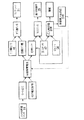
図7は、この燃料電池自動車1における燃料電池11の運転制御方法を示すブロック図である。
燃料電池自動車1では、アクセルペダルAPの踏み込み操作量がアクセル開度としてアクセル開度センサ14で検出され、検出されたアクセル開度に基づいてECU44は走行用モータ13に要求されるモータ出力を算出する。また、ECU44は、燃料電池11を運転するために必要な補機類(例えば、エアコンプレッサ21等)の電気負荷を算出する。
【0053】
次に、走行用モータ13に要求されるモータ出力と補機類の電気負荷に基づいて、電気制御器41により燃料電池11から取り出す目標発電電流IFCを算出し、この目標発電電流IFCに基づいて目標ガス量(目標空気供給量)と目標圧力(目標空気供給圧力)を算出する。
【0054】
そして、前記目標ガス量に基づいてエアコンプレッサ21の回転数Nを算出し、該回転数となるようにエアコンプレッサ21のモータ43を制御するとともに、ガス量センサ46で検出される実際のガス量(実空気供給量)と前記目標ガス量(目標空気供給量)との偏差がゼロになるように、エアコンプレッサ21の回転数のフィードバック制御を行う。
【0055】
また、これと同時に、前記目標圧力に基づいて背圧制御弁25の弁開度θを算出し、該弁開度θになるように背圧制御弁25の開度制御を行うとともに、圧力センサ47で検出される実際の空気供給圧力(実空気供給圧力)と前記目標圧力(目標空気供給圧力)との偏差がゼロになるように、背圧制御弁25の弁開度θのフィードバック制御を行う。
【0056】
また、圧力センサ47で検出された実空気供給圧力(すなわち実作動圧力)と水素センサ54で検出されたFCボックス51内の実水素濃度に基づいて、必要に応じて作動圧力制限値(許容作動圧力)を計算し、前記目標圧力を作動圧力制限値以下に制限するとともに警報を発する。あるいは、作動圧力を制限する代わりに、作動圧力制限値に対応する発電電流制限値(許容発電電流)を計算して、前記目標発電電流を発電電流制限値以下に制限する(図中破線矢印)。このように目標発電電流を制限するようにすると、現在の発電電流から現在の作動圧力を推定可能であることから、圧力センサ47が故障した場合などにも燃料電池11の前記制限運転が可能となり、また、圧力センサ47を省略することも可能となる。
【0057】
このように燃料電池11の運転制御を実行することにより、燃料電池11からの水素漏れ量がある程度増大してくるとワーニングランプの点灯により運転者に注意を喚起することができる。そして、燃料電池11からの水素漏れ量がさらに増大してきて、現運転状態では問題ないが現運転状態よりも作動圧力を増大させて運転すると水素漏れ量が最大水素漏れ量を越える虞があるときには、燃料電池11の出力を制限して運転することにより、水素漏れ量が最大水素漏れ量を越えないように確実に制限することができる。これにより、燃料電池11からの水素漏れ状態を予見しながら燃料電池自動車1を運転することができることとなり、燃料電池11が突然に緊急停止する確率を従来よりも格段に低くすることができる。そして、燃料電池11の出力制限運転を行いながら燃料電池自動車1を修理工場等の所定場所まで移動させることが可能になる。
【0058】
さらに、このように燃料電池11の出力制限運転を行っても燃料電池11からの水素漏れ量が最大水素漏れ量を越えてしまうときには、燃料電池11を緊急停止して安全を確保することができる。
尚、前述した実施の形態では、燃料電池11に供給される空気の圧力を制御対象である作動圧力としたが、制御対象である作動圧力を燃料電池11に供給される水素ガスの圧力とすることも可能である。
【0059】
【発明の効果】
以上説明するように、請求項1に記載した発明によれば、水素センサの検出値に基づいて、前記燃料電池からの水素漏れ量が所定値を越えないように前記作動圧力を制限するので、水素漏れ量を所定値以下に抑制しながら燃料電池の運転を維持することができるという優れた効果が奏される。
【0060】
請求項2に記載した発明によれば、前記効果に加えて、現在の作動圧力での水素漏れ量と前記燃料電池の特性に基づいて、水素漏れ量が前記所定値を越えない作動圧力を予測しているので、水素漏れ量が所定値を越えたことを検知してから作動圧力を制限するのではなく、予め燃料電池の発電電流が小さく、作動圧力が低い状態で運転している時から制限作動圧力を予測して制限するため、確実に水素漏れ量を所定値以下に制限することができるという優れた効果が奏される。
【図面の簡単な説明】
【図1】 この発明の一実施の形態における燃料電池自動車の概略構成図である。
【図2】 前記実施の形態におけるFCボックスの斜視図である。
【図3】 水素漏れ量と水素濃度との関係を示す図である。
【図4】 燃料電池の作動圧力と発電電流との関係を示す図である。
【図5】 燃料電池からの水素漏れ量(水素濃度)と燃料電池の作動圧力との関係を示す図である。
【図6】 燃料電池の運転制御フローチャートの一例である。
【図7】 燃料電池自動車の運転制御ブロック図の一例である。
【符号の説明】
11 燃料電池
54 水素センサ[0001]
BACKGROUND OF THE INVENTION
The present invention relates to a method of operating a fuel cell that generates power using hydrogen gas and an oxidant gas as a reaction gas, and more particularly to a method of operating a fuel cell excellent in safety management against hydrogen leakage.
[0002]
[Prior art]
A fuel cell mounted on a fuel cell vehicle or the like is a stack formed by stacking a plurality of cells formed by sandwiching a solid polymer electrolyte membrane made of, for example, a solid polymer ion exchange membrane between an anode and a cathode from both sides And a hydrogen electrode supplied with hydrogen gas as a fuel gas and an air electrode supplied with air containing oxygen as an oxidant gas. In this fuel cell, hydrogen ions generated by a catalytic reaction at the anode move to the cathode through the solid polymer electrolyte membrane, and generate electricity by causing an electrochemical reaction with oxygen at the cathode.
[0003]
By the way, since hydrogen gas is a flammable gas, sufficient caution is required for leakage into the atmosphere. Generally, in locations where hydrogen is handled, the hydrogen concentration is monitored for safety management, and the detected hydrogen concentration Necessary measures are taken according to the size, and a fuel cell using hydrogen gas as fuel is no exception. On the other hand, since hydrogen is a highly permeable substance, it is extremely difficult to completely shut it off. In particular, the above-mentioned solid polymer electrolyte membrane type fuel cell has a laminated structure, so that hydrogen leaks from the fuel cell. It is difficult to completely block this.
[0004]
Therefore, conventionally, a hydrogen sensor that detects the hydrogen concentration is installed in the vicinity of the fuel cell. When the hydrogen sensor detects a predetermined hydrogen concentration or higher, an alarm is issued or the operation of the fuel cell is stopped. Yes.
Further, for example, as disclosed in JP-A-8-31436, a fuel cell is housed in a ventilable box, and a hydrogen sensor for detecting the hydrogen concentration is installed in the box to thereby adjust the hydrogen concentration in the box. In some cases, the hydrogen concentration in the box is reduced by constantly monitoring and when the hydrogen concentration detected by the hydrogen sensor exceeds a predetermined value, the ventilation fan is operated to perform forced ventilation.
[0005]
[Problems to be solved by the invention]
However, in the case of a system that performs an alarm or stop operation when a predetermined hydrogen concentration is detected by a hydrogen sensor as in the prior art, there may be an emergency stop without predictability. In the case of a fuel cell vehicle, if the operation of the fuel cell is stopped in an emergency as described above, there is a problem that it is not possible to move to a place for repair.
Further, as disclosed in JP-A-8-31436, in the case of a system in which a ventilation fan is operated to forcibly ventilate a box when a predetermined hydrogen concentration is detected by a hydrogen sensor, the amount of hydrogen leakage is reduced. Since it was not controlled, there was a possibility that the amount of hydrogen leakage would continue to increase.
[0006]
Therefore, the present invention utilizes the characteristic that the amount of hydrogen leakage from the fuel cell is correlated with the operating pressure of the fuel cell (that is, the supply pressure of the reaction gas), and the amount of hydrogen leakage increases as the operating pressure increases. The present invention provides a method of operating a fuel cell that limits the operating pressure so that the amount of hydrogen leakage from the fuel cell does not exceed a predetermined value.
[0007]
[Means for Solving the Problems]
In order to solve the above problems, the invention described in claim 1 is directed to a fuel cell (for example, a
[0008]
When the amount of ventilation around the fuel cell is constant, there is a correlation between the amount of hydrogen leakage from the fuel cell and the hydrogen concentration around the fuel cell. Therefore, the amount of hydrogen leakage from the fuel cell can be estimated based on the detection value of the hydrogen sensor. In addition, the amount of hydrogen leakage from the fuel cell depends on the operating pressure of the fuel cell (that is, the supply pressure of the reaction gas), and the hydrogen leakage amount increases as the operating pressure increases. Therefore, based on the detection value of the hydrogen sensor, it is possible to control the operation of the fuel cell by limiting the operating pressure so that the amount of hydrogen leakage from the fuel cell does not exceed a predetermined value.
In addition, when the ventilation volume around the fuel cell is constant, there is a correlation between the hydrogen leak amount from the fuel cell and the hydrogen concentration around the fuel cell, and the hydrogen leak amount from the fuel cell is determined by the operating pressure of the fuel cell ( That is, the operating pressure at which the amount of hydrogen leakage is less than the predetermined value can be predicted from the current hydrogen concentration detected by the hydrogen sensor and the current operating pressure of the fuel cell. Thus, it becomes possible to control the operation of the fuel cell by limiting the operating pressure below the operating pressure.
[0009]
The invention described in claim 2 is the invention described in claim 1,When the hydrogen leakage amount at the current operating pressure is larger than a preset maximum hydrogen leakage amount (for example, the maximum hydrogen concentration Hmax in the embodiment), the fuel cell is stopped.Features.
[0010]
DETAILED DESCRIPTION OF THE INVENTION
Hereinafter, an embodiment of a fuel cell operating method according to the present invention will be described with reference to the drawings of FIGS. This embodiment is an aspect applied to a fuel cell mounted on a fuel cell vehicle.
[0011]
FIG. 1 is a schematic configuration diagram of a fuel cell vehicle.
The fuel cell vehicle 1 includes a hybrid power source device including a
Further, when the driving force is transmitted from the driving wheel W side to the traveling
[0012]
The
[0013]
The air electrode of the
[0014]
For example, the
The air that has been compressed and heated by the
[0015]
Further, in the flow path connecting the
That is, by closing the cooler
[0016]
The
The humidified air is supplied to the
As will be described later, the exhaust air discharged from the
[0017]
The back
[0018]
Hydrogen gas as fuel for the
The fuel
[0019]
The hydrogen gas that has passed through the fuel
[0020]
Further, the unreacted exhaust gas discharged from the hydrogen discharge port 11 d of the
The
[0021]
Further, an
Here, in the ejector
[0022]
That is, the pressure flow characteristic of the hydrogen gas passing through the
That is, the air supply pressure and the hydrogen supply pressure (that is, the operating pressure of the fuel cell 11) supplied to the
[0023]
The
The humidified hydrogen gas is supplied to the
[0024]
The
The
[0025]
The generated current taken out from the
The
[0026]
The
[0027]
The
[0028]
The traveling
For example, the
[0029]
Further, the
[0030]
Further, the
Further, the
[0031]
Then, the rotational speed N and the back pressure of the
[0032]
For this reason, the
The
[0033]
Further, in the fuel cell vehicle 1, as shown in FIG. 2, the
[0034]
The
[0035]
Next, the operation control principle of the
As described above, in the solid polymer electrolyte membrane
[0036]
Therefore, even if a
As described above, when the
[0037]
On the other hand, as described above, the
[0038]
Further, it has been empirically known that the amount of hydrogen leakage from the
[0039]
Note that the amount of hydrogen leakage from the
However, in the
[0040]
From the above, in the
[0041]
Since the hydrogen leakage amount is estimated based on the hydrogen concentration detected by the
[0042]
Further, since the generated current and the operating pressure have a relationship as shown in FIG. 4, the generated current (hereinafter referred to as the allowable generated current) Ilim can be determined corresponding to the allowable operating pressure Plim. Therefore, instead of limiting the operating pressure to the allowable operating pressure Plim and controlling the operation of the fuel cell 1, even if the extraction current from the
[0043]
Next, a method for operating the fuel cell in this embodiment will be described with reference to the flowchart of FIG.
First, the current actual operating pressure Pn detected by the
[0044]
Next, based on the hydrogen leakage characteristics of the fuel cell 11 (see FIG. 5), the hydrogen concentration (expected hydrogen concentration) Hinf in the
[0045]
Next, it is determined whether or not the current actual hydrogen concentration Hn read in step S102 is higher than a maximum hydrogen concentration Hmax (for example, 2%) (step S104).
If the determination result in step S104 is “YES” (Hn> Hmax), the warning lamp is turned on (step S105), the system stop mode is executed (step S106), and the execution of this routine is temporarily terminated. That is, in this case, since the current hydrogen concentration in the FC box 51 (current hydrogen leakage amount from the fuel cell 11) has already exceeded the maximum hydrogen concentration (maximum hydrogen leakage amount) Hmax, the
[0046]
On the other hand, if the determination result in step S104 is “NO” (Hn ≦ Hmax), there is no need to immediately stop immediately, so the process proceeds to step S107, and the predicted hydrogen concentration Hinf calculated in step S103 is greater than the maximum hydrogen concentration Hmax. It is determined whether it is too high.
[0047]
If the determination result in step S107 is “NO” (Hinf ≦ Hmax), the hydrogen concentration can be estimated to be equal to or less than the maximum hydrogen concentration Hmax even if the operation is performed at the maximum operating pressure Pmax. It is determined whether or not the read actual hydrogen concentration Hn is higher than a lower limit hydrogen concentration Hlow (for example, 0.5%) that is a threshold value of the hydrogen concentration safe range.
[0048]
If the determination result in step S108 is “NO” (Hn ≦ Hlow), the current hydrogen concentration in the FC box 51 (current hydrogen leakage from the fuel cell 11) is sufficiently low and is in a safe range. Proceeding to step S109, the output limit value (allowable power generation current Ilim) calculated at step S113 described later is initialized, and the execution of this routine is once ended.
[0049]
If the determination result in step S108 is “YES” (Hn> Hlow), the process proceeds to step S110, the warning lamp is turned on, and the execution of this routine is temporarily terminated. This is because the current hydrogen concentration in the FC box 51 (current hydrogen leakage amount from the fuel cell 11) is less than the maximum hydrogen concentration (maximum hydrogen leakage amount) Hmax, but the lower limit hydrogen concentration (lower limit hydrogen leakage amount) Hlow is reduced. Since it exceeds the limit, an alarm is issued to alert the driver.
[0050]
On the other hand, if the determination result in step S107 is “YES” (Hinf> Hmax), the current hydrogen concentration in the FC box 51 (current hydrogen leakage amount from the fuel cell 11) is the maximum hydrogen concentration (maximum hydrogen leakage). The amount of hydrogen in the FC box 51 (the amount of hydrogen leakage from the fuel cell 11) is expected to exceed the maximum amount of hydrogen (the maximum amount of hydrogen leakage) Hmax if it is operated at the maximum operating pressure Pmax. Therefore, operation at the maximum operating pressure Pmax should be avoided. Therefore, if the determination result in step S107 is “YES”, after turning on the warning lamp in step S111, the process proceeds to step S112, where the allowable hydrogen concentration (allowable hydrogen leakage amount) Hlim (eg, 1.9%) is reached. The corresponding allowable operating pressure Plim is calculated by referring to the map or by calculation. In this embodiment, the allowable hydrogen concentration (allowable hydrogen leakage amount) Hlim is set slightly lower than the maximum hydrogen concentration (maximum hydrogen leakage amount) Hmax in consideration of safety, but can be set to the same value. is there.
[0051]
Next, the allowable generated current Ilim corresponding to the allowable operating pressure Plim is calculated by referring to the map or by calculation (step S113), and the output limited operation mode is executed with the allowable generated current Ilim as an output limit value (step S114). Routine execution is temporarily terminated. In the output limited operation mode, the operation control of the
[0052]
FIG. 7 is a block diagram showing an operation control method for the
In the fuel cell vehicle 1, the depression amount of the accelerator pedal AP is detected by the
[0053]
Next, based on the motor output required for the traveling
[0054]
Then, the rotational speed N of the
[0055]
At the same time, the valve opening degree θ of the back
[0056]
Further, based on the actual air supply pressure (that is, actual operating pressure) detected by the
[0057]
By executing the operation control of the
[0058]
Further, when the amount of hydrogen leakage from the
In the above-described embodiment, the pressure of the air supplied to the
[0059]
【Effect of the invention】
As described above, according to the invention described in claim 1, the operating pressure is limited based on the detection value of the hydrogen sensor so that the amount of hydrogen leakage from the fuel cell does not exceed a predetermined value. There is an excellent effect that the operation of the fuel cell can be maintained while suppressing the hydrogen leakage amount to a predetermined value or less.
[0060]
According to the second aspect of the present invention, in addition to the above effect, the operating pressure at which the amount of hydrogen leakage does not exceed the predetermined value is predicted based on the amount of hydrogen leakage at the current operating pressure and the characteristics of the fuel cell. Therefore, instead of limiting the operating pressure after detecting that the amount of hydrogen leakage has exceeded a predetermined value, it is possible to start from when the fuel cell is operating in a state where the generated current is small and the operating pressure is low. Since the limit operating pressure is predicted and limited, an excellent effect that the amount of hydrogen leakage can be surely limited to a predetermined value or less is exhibited.
[Brief description of the drawings]
FIG. 1 is a schematic configuration diagram of a fuel cell vehicle according to an embodiment of the present invention.
FIG. 2 is a perspective view of the FC box in the embodiment.
FIG. 3 is a diagram showing the relationship between hydrogen leakage and hydrogen concentration.
FIG. 4 is a diagram showing the relationship between the operating pressure of a fuel cell and the generated current.
FIG. 5 is a graph showing the relationship between the amount of hydrogen leakage from the fuel cell (hydrogen concentration) and the operating pressure of the fuel cell.
FIG. 6 is an example of a fuel cell operation control flowchart.
FIG. 7 is an example of an operation control block diagram of a fuel cell vehicle.
[Explanation of symbols]
11 Fuel cell
54 Hydrogen sensor
Claims (2)
前記燃料電池の周辺に水素濃度を検出して信号を出力する水素センサを設け、
該水素センサの検出値から得られる現在の作動圧力での水素漏れ量と、前記燃料電池における作動圧力に対する水素漏れ量の変化率と、に基づいて、水素漏れ量が所定値を超えない作動圧力を予測し、該作動圧力以下に作動圧力を制限することを特徴とする燃料電池の運転方法。A fuel cell that generates power using hydrogen gas and oxidant gas as the reaction gas, adjusts the hydrogen gas pressure based on the oxidant gas pressure, and requires the required power generation while keeping the pressure difference between the fuel electrode and the air electrode within a specified range. In the operation method of the fuel cell that operates at the operating pressure of at least one of the hydrogen gas pressure and the oxidant gas pressure according to the state,
A hydrogen sensor that detects a hydrogen concentration and outputs a signal around the fuel cell is provided,
Based on the hydrogen leak amount at the current operating pressure obtained from the detection value of the hydrogen sensor and the rate of change of the hydrogen leak amount with respect to the operating pressure in the fuel cell, the operating pressure at which the hydrogen leak amount does not exceed a predetermined value And the operating pressure is limited to be equal to or lower than the operating pressure.
Priority Applications (4)
| Application Number | Priority Date | Filing Date | Title |
|---|---|---|---|
| JP2001203939A JP5128032B2 (en) | 2001-07-04 | 2001-07-04 | Operation method of fuel cell |
| CA002390221A CA2390221C (en) | 2001-07-04 | 2002-07-02 | Fuel cell operation method |
| US10/187,933 US7087334B2 (en) | 2001-07-04 | 2002-07-02 | Fuel cell operation method |
| DE10229644A DE10229644B4 (en) | 2001-07-04 | 2002-07-02 | Fuel cells operating procedures |
Applications Claiming Priority (1)
| Application Number | Priority Date | Filing Date | Title |
|---|---|---|---|
| JP2001203939A JP5128032B2 (en) | 2001-07-04 | 2001-07-04 | Operation method of fuel cell |
Publications (2)
| Publication Number | Publication Date |
|---|---|
| JP2003017094A JP2003017094A (en) | 2003-01-17 |
| JP5128032B2 true JP5128032B2 (en) | 2013-01-23 |
Family
ID=19040491
Family Applications (1)
| Application Number | Title | Priority Date | Filing Date |
|---|---|---|---|
| JP2001203939A Expired - Fee Related JP5128032B2 (en) | 2001-07-04 | 2001-07-04 | Operation method of fuel cell |
Country Status (4)
| Country | Link |
|---|---|
| US (1) | US7087334B2 (en) |
| JP (1) | JP5128032B2 (en) |
| CA (1) | CA2390221C (en) |
| DE (1) | DE10229644B4 (en) |
Families Citing this family (39)
| Publication number | Priority date | Publication date | Assignee | Title |
|---|---|---|---|---|
| JP3816436B2 (en) * | 2002-11-28 | 2006-08-30 | 本田技研工業株式会社 | Control device for fuel cell vehicle |
| JP4202100B2 (en) * | 2002-11-29 | 2008-12-24 | 本田技研工業株式会社 | Function maintenance method of fuel cell system |
| JP4142948B2 (en) * | 2002-12-24 | 2008-09-03 | 本田技研工業株式会社 | Hydrogen supply method |
| JP4325216B2 (en) * | 2003-02-20 | 2009-09-02 | 日産自動車株式会社 | Control device for fuel cell plant |
| JP4501351B2 (en) * | 2003-03-27 | 2010-07-14 | 日産自動車株式会社 | Fuel cell system |
| JP4876369B2 (en) * | 2003-06-19 | 2012-02-15 | トヨタ自動車株式会社 | Fuel cell system and gas leak detection method |
| JP2005062532A (en) * | 2003-08-14 | 2005-03-10 | Fuji Photo Film Co Ltd | camera |
| JP4622313B2 (en) * | 2003-08-26 | 2011-02-02 | トヨタ自動車株式会社 | Moving body |
| US7368192B2 (en) * | 2003-09-17 | 2008-05-06 | General Motors Corporation | Method and apparatus for hydrogen detection and dilution |
| US7309537B2 (en) * | 2003-09-18 | 2007-12-18 | Ballard Power Systems Inc. | Fuel cell system with fluid stream recirculation |
| CN100511799C (en) * | 2003-10-01 | 2009-07-08 | 松下电器产业株式会社 | Fuel cell power-generating system |
| DE112004002487D2 (en) * | 2003-10-13 | 2006-08-24 | P21 Power For The 21St Century | The fuel cell system |
| JP4692869B2 (en) | 2003-10-24 | 2011-06-01 | トヨタ自動車株式会社 | Abnormality detection device for fuel cell system |
| US7350604B2 (en) * | 2004-03-04 | 2008-04-01 | Ford Global Technologies, Llc | Gaseous fuel system for automotive vehicle |
| US7901815B2 (en) * | 2004-07-14 | 2011-03-08 | Honeywell International Inc. | Fuel cell power generator utilizing substantially or completely closed water supply |
| JP4889931B2 (en) * | 2004-08-30 | 2012-03-07 | 株式会社荏原製作所 | FUEL CELL UNIT AND METHOD OF OPERATING FUEL CELL UNIT |
| JP4296144B2 (en) * | 2004-09-29 | 2009-07-15 | 本田技研工業株式会社 | Fuel cell motorcycle |
| WO2006070917A1 (en) * | 2004-12-27 | 2006-07-06 | Toyota Jidosha Kabushiki Kaisha | Fuel cell failure detection device, operation device, and operation method |
| US20070196705A1 (en) * | 2004-12-28 | 2007-08-23 | Matsushita Electric Industrial Co., Ltd. | Fuel cell system |
| DE102005009674A1 (en) * | 2005-02-28 | 2006-08-31 | Robert Bosch Gmbh | Fuel cell system for use in motor vehicle, has compressor driven by high pressure of primary fuel and/or hydrogen, where primary hydrogen flows via pressure-reduction valve into compressor |
| JP4862283B2 (en) * | 2005-05-24 | 2012-01-25 | 日産自動車株式会社 | Fuel cell |
| JP5105218B2 (en) * | 2005-06-06 | 2012-12-26 | トヨタ自動車株式会社 | Abnormality judgment device |
| JP4736612B2 (en) | 2005-08-11 | 2011-07-27 | トヨタ自動車株式会社 | Moving body |
| US7855025B2 (en) * | 2005-11-21 | 2010-12-21 | Ford Global Technologies | Anode loop pressure control in PEM fuel cell system |
| KR100718116B1 (en) * | 2006-05-15 | 2007-05-15 | 삼성에스디아이 주식회사 | High Temperature PEM Fuel Cell System |
| JP5067524B2 (en) | 2006-07-26 | 2012-11-07 | トヨタ自動車株式会社 | Fuel cell system and control method thereof |
| JP4910791B2 (en) * | 2007-03-12 | 2012-04-04 | トヨタ自動車株式会社 | Fuel cell system |
| US7576660B2 (en) * | 2007-05-30 | 2009-08-18 | Ford Global Technologies, Llc | Fuel retention monitoring system for a pressurized hydrogen storage tank on a vehicle and method of use |
| KR20090007013A (en) * | 2007-07-13 | 2009-01-16 | 현대자동차주식회사 | Ventilation device of fuel cell vehicle |
| JP4353297B2 (en) * | 2007-10-17 | 2009-10-28 | トヨタ自動車株式会社 | vehicle |
| DE102008010711B4 (en) * | 2008-02-21 | 2018-04-26 | Audi Ag | Method for operating a fuel cell system and fuel cell system with a regulator assembly |
| US20110207013A1 (en) * | 2010-02-21 | 2011-08-25 | Adaptive Materials, Inc. | Multiple flow stream sensor |
| GB2507042B (en) | 2012-10-16 | 2018-07-11 | Schlumberger Holdings | Electrochemical hydrogen sensor |
| KR101481233B1 (en) * | 2012-12-07 | 2015-01-09 | 현대자동차주식회사 | Apparatus for supplying air of fuel cell vehicle |
| DE102014203259A1 (en) * | 2014-02-24 | 2015-08-27 | Bayerische Motoren Werke Aktiengesellschaft | Fuel cell system with a housing arranged in a fuel cell stack and a measure for housing ventilation |
| DE102015225600A1 (en) * | 2015-12-17 | 2017-06-22 | Robert Bosch Gmbh | Method for diagnosing a leak and fuel cell system |
| CN110752394B (en) * | 2019-09-25 | 2021-07-20 | 潍柴动力股份有限公司 | Fuel cell leak detection method and detection system |
| CN111129545B (en) * | 2019-12-28 | 2020-12-22 | 绍兴市上虞区理工高等研究院 | Vehicle fuel cell hydrogen supply circulation system and control method |
| US11913581B2 (en) * | 2021-07-20 | 2024-02-27 | FirstElement Fuel, Inc. | Control conduit for LH2 offloading |
Family Cites Families (11)
| Publication number | Priority date | Publication date | Assignee | Title |
|---|---|---|---|---|
| US3748180A (en) * | 1972-03-30 | 1973-07-24 | Us Navy | Fuel cell system for underwater vehicle |
| JPS57205971A (en) * | 1981-06-12 | 1982-12-17 | Hitachi Ltd | Operating method of fuel cell |
| JPH0773056B2 (en) * | 1985-08-30 | 1995-08-02 | 株式会社日立製作所 | Fuel cell |
| JPH03250564A (en) * | 1990-02-28 | 1991-11-08 | Toshiba Corp | Fuel cell power generating system |
| JPH0831436A (en) * | 1994-07-13 | 1996-02-02 | Toshiba Corp | Packaged fuel cell power plant |
| US5763113A (en) * | 1996-08-26 | 1998-06-09 | General Motors Corporation | PEM fuel cell monitoring system |
| JP2000274894A (en) * | 1999-03-18 | 2000-10-06 | Sanyo Electric Co Ltd | Heat pump |
| US6280869B1 (en) * | 1999-07-29 | 2001-08-28 | Nexant, Inc. | Fuel cell stack system and operating method |
| JP3504898B2 (en) * | 1999-11-16 | 2004-03-08 | 三菱重工業株式会社 | Polymer electrolyte fuel cell |
| US6461751B1 (en) * | 1999-12-06 | 2002-10-08 | Ballard Power Systems Inc. | Method and apparatus for operating a fuel cell |
| US6887606B2 (en) * | 2001-07-25 | 2005-05-03 | Ballard Power Systems Inc. | Fuel cell system method and apparatus employing oxygen sensor |
-
2001
- 2001-07-04 JP JP2001203939A patent/JP5128032B2/en not_active Expired - Fee Related
-
2002
- 2002-07-02 DE DE10229644A patent/DE10229644B4/en not_active Expired - Fee Related
- 2002-07-02 US US10/187,933 patent/US7087334B2/en not_active Expired - Fee Related
- 2002-07-02 CA CA002390221A patent/CA2390221C/en not_active Expired - Fee Related
Also Published As
| Publication number | Publication date |
|---|---|
| US7087334B2 (en) | 2006-08-08 |
| CA2390221C (en) | 2006-11-07 |
| JP2003017094A (en) | 2003-01-17 |
| DE10229644B4 (en) | 2008-08-07 |
| CA2390221A1 (en) | 2003-01-04 |
| US20030008185A1 (en) | 2003-01-09 |
| DE10229644A1 (en) | 2003-02-13 |
Similar Documents
| Publication | Publication Date | Title |
|---|---|---|
| JP5128032B2 (en) | Operation method of fuel cell | |
| JP4672183B2 (en) | Fuel cell control device and fuel cell vehicle control device | |
| KR101136497B1 (en) | Fuel cell system and its control method | |
| US8415065B2 (en) | Fuel cell system and method of controlling fuel cell system | |
| KR101000703B1 (en) | Idle stop / release control method of fuel cell hybrid vehicle | |
| CA2641201C (en) | Fuel cell system having controller controlling higher-efficiency operation and lower-efficiency operation | |
| KR101135654B1 (en) | Fuel cell system and control method of the system | |
| US9793558B2 (en) | Fuel cell system | |
| KR101151748B1 (en) | Fuel cell system and fuel cell vehicle | |
| CA2911358C (en) | Fuel cell system and operation control method for restoration to normal operation | |
| JP4789018B2 (en) | Fuel cell system | |
| US20070218328A1 (en) | Fuel cell system | |
| US8053124B2 (en) | Fuel cell system and mobile body | |
| WO2008062807A1 (en) | Fuel cell system | |
| CN112572237B (en) | Vehicle system, control method of vehicle system, and storage medium | |
| JP2014056771A (en) | External feeder controller for fuel cell vehicle | |
| CN112582712A (en) | Fuel cell system, control method of fuel cell system, and storage medium | |
| JP2002352826A (en) | Fuel cell control device | |
| EP1953857B1 (en) | Fuel cell system | |
| JP4337104B2 (en) | Fuel cell system | |
| JP2004165087A (en) | Control device for fuel cell stack | |
| JP2008282778A (en) | Fuel cell system and scavenging method for fuel cell |
Legal Events
| Date | Code | Title | Description |
|---|---|---|---|
| A621 | Written request for application examination |
Free format text: JAPANESE INTERMEDIATE CODE: A621 Effective date: 20071126 |
|
| A977 | Report on retrieval |
Free format text: JAPANESE INTERMEDIATE CODE: A971007 Effective date: 20110428 |
|
| A131 | Notification of reasons for refusal |
Free format text: JAPANESE INTERMEDIATE CODE: A131 Effective date: 20110510 |
|
| A521 | Written amendment |
Free format text: JAPANESE INTERMEDIATE CODE: A523 Effective date: 20110707 |
|
| A131 | Notification of reasons for refusal |
Free format text: JAPANESE INTERMEDIATE CODE: A131 Effective date: 20120306 |
|
| A521 | Written amendment |
Free format text: JAPANESE INTERMEDIATE CODE: A523 Effective date: 20120424 |
|
| TRDD | Decision of grant or rejection written | ||
| A01 | Written decision to grant a patent or to grant a registration (utility model) |
Free format text: JAPANESE INTERMEDIATE CODE: A01 Effective date: 20121023 |
|
| A01 | Written decision to grant a patent or to grant a registration (utility model) |
Free format text: JAPANESE INTERMEDIATE CODE: A01 |
|
| A61 | First payment of annual fees (during grant procedure) |
Free format text: JAPANESE INTERMEDIATE CODE: A61 Effective date: 20121031 |
|
| R150 | Certificate of patent or registration of utility model |
Free format text: JAPANESE INTERMEDIATE CODE: R150 |
|
| FPAY | Renewal fee payment (event date is renewal date of database) |
Free format text: PAYMENT UNTIL: 20151109 Year of fee payment: 3 |
|
| LAPS | Cancellation because of no payment of annual fees |