JP5201873B2 - Drive device - Google Patents

Drive device Download PDF

Info

Publication number
JP5201873B2
JP5201873B2 JP2007122574A JP2007122574A JP5201873B2 JP 5201873 B2 JP5201873 B2 JP 5201873B2 JP 2007122574 A JP2007122574 A JP 2007122574A JP 2007122574 A JP2007122574 A JP 2007122574A JP 5201873 B2 JP5201873 B2 JP 5201873B2
Authority
JP
Japan
Prior art keywords
driver
piezoelectric element
stage
electrode
piezoelectric
Prior art date
Legal status (The legal status is an assumption and is not a legal conclusion. Google has not performed a legal analysis and makes no representation as to the accuracy of the status listed.)
Expired - Fee Related
Application number
JP2007122574A
Other languages
Japanese (ja)
Other versions
JP2008278720A5 (en
JP2008278720A (en
Inventor
賢 東陰地
秀明 向江
祐介 足立
英一 長岡
Current Assignee (The listed assignees may be inaccurate. Google has not performed a legal analysis and makes no representation or warranty as to the accuracy of the list.)
Panasonic Corp
Panasonic Holdings Corp
Original Assignee
Panasonic Corp
Matsushita Electric Industrial Co Ltd
Priority date (The priority date is an assumption and is not a legal conclusion. Google has not performed a legal analysis and makes no representation as to the accuracy of the date listed.)
Filing date
Publication date
Application filed by Panasonic Corp, Matsushita Electric Industrial Co Ltd filed Critical Panasonic Corp
Priority to JP2007122574A priority Critical patent/JP5201873B2/en
Priority to US12/114,891 priority patent/US7679265B2/en
Publication of JP2008278720A publication Critical patent/JP2008278720A/en
Publication of JP2008278720A5 publication Critical patent/JP2008278720A5/ja
Application granted granted Critical
Publication of JP5201873B2 publication Critical patent/JP5201873B2/en
Expired - Fee Related legal-status Critical Current
Anticipated expiration legal-status Critical

Links

Images

Classifications

    • HELECTRICITY
    • H10SEMICONDUCTOR DEVICES; ELECTRIC SOLID-STATE DEVICES NOT OTHERWISE PROVIDED FOR
    • H10NELECTRIC SOLID-STATE DEVICES NOT OTHERWISE PROVIDED FOR
    • H10N30/00Piezoelectric or electrostrictive devices
    • H10N30/20Piezoelectric or electrostrictive devices with electrical input and mechanical output, e.g. functioning as actuators or vibrators
    • H10N30/202Piezoelectric or electrostrictive devices with electrical input and mechanical output, e.g. functioning as actuators or vibrators using longitudinal or thickness displacement combined with bending, shear or torsion displacement
    • GPHYSICS
    • G01MEASURING; TESTING
    • G01BMEASURING LENGTH, THICKNESS OR SIMILAR LINEAR DIMENSIONS; MEASURING ANGLES; MEASURING AREAS; MEASURING IRREGULARITIES OF SURFACES OR CONTOURS
    • G01B7/00Measuring arrangements characterised by the use of electric or magnetic techniques
    • G01B7/003Measuring arrangements characterised by the use of electric or magnetic techniques for measuring position, not involving coordinate determination
    • GPHYSICS
    • G01MEASURING; TESTING
    • G01BMEASURING LENGTH, THICKNESS OR SIMILAR LINEAR DIMENSIONS; MEASURING ANGLES; MEASURING AREAS; MEASURING IRREGULARITIES OF SURFACES OR CONTOURS
    • G01B7/00Measuring arrangements characterised by the use of electric or magnetic techniques
    • G01B7/02Measuring arrangements characterised by the use of electric or magnetic techniques for measuring length, width or thickness
    • G01B7/023Measuring arrangements characterised by the use of electric or magnetic techniques for measuring length, width or thickness for measuring distance between sensor and object
    • HELECTRICITY
    • H02GENERATION; CONVERSION OR DISTRIBUTION OF ELECTRIC POWER
    • H02NELECTRIC MACHINES NOT OTHERWISE PROVIDED FOR
    • H02N2/00Electric machines in general using piezoelectric effect, electrostriction or magnetostriction
    • H02N2/0005Electric machines in general using piezoelectric effect, electrostriction or magnetostriction producing non-specific motion; Details common to machines covered by H02N2/02 - H02N2/16
    • H02N2/001Driving devices, e.g. vibrators
    • H02N2/003Driving devices, e.g. vibrators using longitudinal or radial modes combined with bending modes
    • H02N2/004Rectangular vibrators
    • HELECTRICITY
    • H02GENERATION; CONVERSION OR DISTRIBUTION OF ELECTRIC POWER
    • H02NELECTRIC MACHINES NOT OTHERWISE PROVIDED FOR
    • H02N2/00Electric machines in general using piezoelectric effect, electrostriction or magnetostriction
    • H02N2/02Electric machines in general using piezoelectric effect, electrostriction or magnetostriction producing linear motion, e.g. actuators; Linear positioners ; Linear motors
    • H02N2/026Electric machines in general using piezoelectric effect, electrostriction or magnetostriction producing linear motion, e.g. actuators; Linear positioners ; Linear motors by pressing one or more vibrators against the driven body
    • HELECTRICITY
    • H02GENERATION; CONVERSION OR DISTRIBUTION OF ELECTRIC POWER
    • H02NELECTRIC MACHINES NOT OTHERWISE PROVIDED FOR
    • H02N2/00Electric machines in general using piezoelectric effect, electrostriction or magnetostriction
    • H02N2/02Electric machines in general using piezoelectric effect, electrostriction or magnetostriction producing linear motion, e.g. actuators; Linear positioners ; Linear motors
    • H02N2/06Drive circuits; Control arrangements or methods
    • H02N2/062Small signal circuits; Means for controlling position or derived quantities, e.g. for removing hysteresis
    • HELECTRICITY
    • H10SEMICONDUCTOR DEVICES; ELECTRIC SOLID-STATE DEVICES NOT OTHERWISE PROVIDED FOR
    • H10NELECTRIC SOLID-STATE DEVICES NOT OTHERWISE PROVIDED FOR
    • H10N30/00Piezoelectric or electrostrictive devices
    • H10N30/20Piezoelectric or electrostrictive devices with electrical input and mechanical output, e.g. functioning as actuators or vibrators
    • H10N30/202Piezoelectric or electrostrictive devices with electrical input and mechanical output, e.g. functioning as actuators or vibrators using longitudinal or thickness displacement combined with bending, shear or torsion displacement
    • H10N30/2023Piezoelectric or electrostrictive devices with electrical input and mechanical output, e.g. functioning as actuators or vibrators using longitudinal or thickness displacement combined with bending, shear or torsion displacement having polygonal or rectangular shape

Landscapes

  • Physics & Mathematics (AREA)
  • General Physics & Mathematics (AREA)
  • General Electrical Machinery Utilizing Piezoelectricity, Electrostriction Or Magnetostriction (AREA)

Description

本発明は、振動型アクチュエータによって可動体を固定体に対して相対的に移動させる駆動装置に関するものである。   The present invention relates to a drive device that moves a movable body relative to a fixed body by a vibration type actuator.

従来より、振動型アクチュエータを備えた駆動装置は知られている。例えば、超音波モータや微小ステップで移動する装置などで利用されている。   2. Description of the Related Art Conventionally, a drive device including a vibration type actuator is known. For example, it is used in an ultrasonic motor or a device that moves in micro steps.

かかる駆動装置においては、可動体を単に移動させるだけでなく、可動体の位置制御を行う必要がある。例えば、特許文献1に開示された駆動装置では、位置検出センサとしての光学式リニアエンコーダを別途備え、該光学式リニアエンコーダによって可動体の現在位置を検出すると共に、その現在位置に基づいて振動型アクチュエータへの駆動信号を制御している。
特開2002−374686号公報
In such a drive device, it is necessary not only to move the movable body but also to control the position of the movable body. For example, the drive device disclosed in Patent Document 1 is additionally provided with an optical linear encoder as a position detection sensor, detects the current position of the movable body with the optical linear encoder, and uses the vibration type based on the current position. The drive signal to the actuator is controlled.
JP 2002-374686 A

しかしながら、位置検出センサを別途設ける構成は、駆動装置のコストを増大させると共に、サイズを大きくしてしまう。例えば、可動体の移動範囲の全域に亘ってスケール等を配置することが必要な位置検出センサでは、サイズの大型化が特に問題となる。振動型アクチュエータは小形のものも多く、そのような場合にも、位置検出センサによるサイズの増大が問題となる。そのため、簡便な構成で且つコストパフォーマンスが優れた、位置を検出するための構成が要望される。   However, the configuration in which the position detection sensor is separately provided increases the cost of the driving device and increases the size. For example, in a position detection sensor that needs to arrange a scale or the like over the entire moving range of the movable body, an increase in size is particularly problematic. Many of the vibration type actuators are small, and even in such a case, an increase in size due to the position detection sensor becomes a problem. Therefore, there is a demand for a configuration for detecting a position with a simple configuration and excellent cost performance.

そこで、圧電素子への給電時間又は駆動周波数を目安に可動体の位置を算出することも考えられる。しかし、この方法では駆動子そのものの動作は推定できても、駆動子と可動体との間には滑り等が存在し、駆動子が出力する駆動力の全てが可動体に伝達するわけではないため、可動体の位置を高精度に推定することは困難である。   In view of this, it is conceivable to calculate the position of the movable body based on the power supply time or drive frequency to the piezoelectric element. However, even if the operation of the driver itself can be estimated by this method, there is a slip between the driver and the movable body, and not all the driving force output by the driver is transmitted to the movable body. Therefore, it is difficult to estimate the position of the movable body with high accuracy.

本発明は、かかる点に鑑みてなされたものであり、その目的とするところは、可動体の位置検出を簡易な構成で実現することにある。   The present invention has been made in view of such a point, and an object thereof is to realize position detection of a movable body with a simple configuration.

本発明は、固定体と、該固定体に対して相対的に移動可能な可動体と、圧電素子を用いて構成され該可動体を移動させる振動型アクチュエータと、該圧電素子に給電することによって振動型アクチュエータを制御する制御部とを備えた駆動装置が対象である。そして、前記振動型アクチュエータは、前記可動体及び前記固定体のうちの一方に接触する駆動子を有すると共に、該可動体及び固定体のうちの他方に取り付けられており、前記可動体及び固定体のうちの一方における前記駆動子が接触する面には、凹凸部が形成されており、前記制御部は、前記駆動子の接触圧力の変化に基づいて前記可動体の位置を検出するようにしたものである。   The present invention provides a fixed body, a movable body that can move relative to the fixed body, a vibration type actuator that uses a piezoelectric element to move the movable body, and supplies power to the piezoelectric element. A drive device including a control unit that controls a vibration type actuator is an object. The vibration-type actuator has a driver that contacts one of the movable body and the fixed body, and is attached to the other of the movable body and the fixed body. The movable body and the fixed body An uneven portion is formed on a surface of the driving element that contacts the driving element, and the control unit detects the position of the movable body based on a change in the contact pressure of the driving element. Is.

本発明によれば、振動型アクチュエータの駆動子が接触する、固定体及び可動体のうちの一方に凹凸部を形成することによって、駆動子が可動体を駆動する際の該駆動子の接触圧力が変化するため、該駆動子の圧力変化に基づいて可動体の位置を検出することができ、その結果、位置検出センサを別途設けることなく、簡易な構成で可動体の位置を検出することができる。   According to the present invention, the contact pressure of the driver when the driver drives the movable body by forming an uneven portion on one of the fixed body and the movable body that the driver of the vibration actuator contacts. Therefore, the position of the movable body can be detected based on the pressure change of the driver, and as a result, the position of the movable body can be detected with a simple configuration without providing a position detection sensor separately. it can.

以下、本発明の実施形態を図面に基づいて詳細に説明する。   Hereinafter, embodiments of the present invention will be described in detail with reference to the drawings.

《発明の実施形態1》
本発明の実施形態1に係る駆動装置1は、図1、2に示すように、ステージ11と、超音波アクチュエータ2と、該超音波アクチュエータ2を駆動制御する制御装置7とを備えている。
Embodiment 1 of the Invention
As shown in FIGS. 1 and 2, the drive device 1 according to Embodiment 1 of the present invention includes a stage 11, an ultrasonic actuator 2, and a control device 7 that drives and controls the ultrasonic actuator 2.

ステージ11は、互いに平行な状態で固定体としての基台(図示省略)上に固定されたガイド13,13に摺動可能に取り付けられている。つまり、ステージ11は、ガイド13,13が延びる方向に沿って移動可能に構成されている(これらガイド13,13の延びる方向がステージ11の可動方向に相当する)。このステージ11は、平面視略方形の板状部材である。そして、前記超音波アクチュエータ2は、このステージ11の裏面(ガイド13,13が設けられている側の面)に後述する駆動子49,49が接触するように配設されている。このステージ11が可動体を構成し、基台及びガイド13が固定体を構成する。   The stage 11 is slidably attached to guides 13 and 13 fixed on a base (not shown) as a fixed body in a state parallel to each other. That is, the stage 11 is configured to be movable along the direction in which the guides 13 and 13 extend (the direction in which the guides 13 and 13 extend corresponds to the movable direction of the stage 11). This stage 11 is a plate-like member having a substantially square shape in plan view. The ultrasonic actuator 2 is arranged such that driver elements 49 and 49 described later are in contact with the back surface of the stage 11 (the surface on which the guides 13 and 13 are provided). The stage 11 constitutes a movable body, and the base and the guide 13 constitute a fixed body.

前記超音波アクチュエータ2は、図3に示すように、振動を発生させるアクチュエータ本体4と、該アクチュエータ本体4の駆動力をステージ11に伝達させる駆動子49,49と、該アクチュエータ本体4を収容するケース5と、アクチュエータ本体4とケース5との間に介設されてアクチュエータ本体4を弾性的に支持する支持ゴム61,61と、アクチュエータ本体4を前記ステージ11に付勢するための付勢ゴム62とを備えている。この超音波アクチュエータ2が振動型アクチュエータを構成する。   As shown in FIG. 3, the ultrasonic actuator 2 accommodates an actuator body 4 that generates vibration, driver elements 49 and 49 that transmit a driving force of the actuator body 4 to the stage 11, and the actuator body 4. A case 5, support rubbers 61 and 61 interposed between the actuator body 4 and the case 5 to elastically support the actuator body 4, and a biasing rubber for biasing the actuator body 4 to the stage 11 62. This ultrasonic actuator 2 constitutes a vibration type actuator.

前記アクチュエータ本体4は、圧電素子ユニット40で構成されている。   The actuator body 4 is composed of a piezoelectric element unit 40.

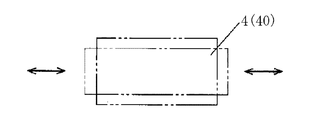
前記圧電素子ユニット40は、略長方形状の互いに対向する一対の主面と、この主面と直交して該主面の長手方向に延びる、互いに対向する一対の長辺側面と、これら主面及び長辺側面の両方と直交して該主面の短手方向に延びる、互いに対向する一対の短辺側面とを有する略直方体状をしている。   The piezoelectric element unit 40 includes a pair of substantially rectangular main surfaces facing each other, a pair of long side surfaces facing each other perpendicular to the main surface and extending in the longitudinal direction of the main surface, the main surfaces, It has a substantially rectangular parallelepiped shape having a pair of short side surfaces facing each other and extending in the short direction of the main surface perpendicular to both of the long side surfaces.

この圧電素子ユニット40は、図4に示すように、5つの圧電体層(圧電素子)41,41,…と4つの内部電極層42,44,43,44とを交互に積層して構成される。内部電極層42,44,43,44は、積層方向に圧電体層41を介して交互に配された、第1プラス側電極層42と共通マイナス側電極層44と第2プラス側電極層43と共通マイナス側電極層44とで構成される。これら第1プラス側電極層42、第2プラス側電極層43及び共通マイナス側電極層44,44のそれぞれは、各圧電体層41の主面上に印刷されている。   As shown in FIG. 4, the piezoelectric element unit 40 is configured by alternately stacking five piezoelectric layers (piezoelectric elements) 41, 41,... And four internal electrode layers 42, 44, 43, 44. The The internal electrode layers 42, 44, 43, 44 are alternately arranged in the stacking direction via the piezoelectric layers 41, the first plus electrode layer 42, the common minus electrode layer 44, and the second plus electrode layer 43. And the common negative electrode layer 44. Each of the first plus side electrode layer 42, the second plus side electrode layer 43, and the common minus side electrode layers 44, 44 is printed on the main surface of each piezoelectric layer 41.

前記各圧電体層41は、例えばチタン酸ジルコン酸鉛などのセラミック材料からなる絶縁体層であって、前記圧電素子ユニット40と同様に、一対の主面と、一対の長辺側面と、一対の短辺側面とを有する略直方体状をしている。また、各圧電体層41には、その長辺側面のうち一方の長辺側面の長手方向中央部に外部電極48aが、一方の短辺側面の短手方向中央部に外部電極46aが、他方の短辺側面の短手方向中央部に外部電極47aがそれぞれ形成されている。   Each of the piezoelectric layers 41 is an insulating layer made of a ceramic material such as lead zirconate titanate, and similarly to the piezoelectric element unit 40, a pair of main surfaces, a pair of long side surfaces, and a pair It has a substantially rectangular parallelepiped shape having a short side surface. Each piezoelectric layer 41 has an external electrode 48a at the longitudinal center of one of the long side surfaces, an external electrode 46a at the lateral center of one short side, External electrodes 47a are respectively formed in the center portion in the short direction of the short side surface.

前記各共通マイナス側電極層44は、圧電体層41の主面の略全面に亘って設けられた略長方形状をしている。また、各共通電極層44の一方の長辺部には、その長手方向中央部から圧電体層41の前記外部電極48aまで延びる引出電極44dが形成されている。   Each of the common negative electrode layers 44 has a substantially rectangular shape provided over substantially the entire main surface of the piezoelectric layer 41. In addition, on one long side portion of each common electrode layer 44, an extraction electrode 44d extending from the central portion in the longitudinal direction to the external electrode 48a of the piezoelectric layer 41 is formed.

前記第1プラス側電極層42は、図5に示すように、圧電体層41の主面をその長手方向及び短手方向にそれぞれ2等分してなる4つの領域のうち該主面の対角線方向に位置する2対の領域のうち一方の対の領域にそれぞれ形成された一対の第1電極42a,42bと、これら第1電極42a,42bを連結して導通させる導通電極42cとを有する。各第1電極42a(42b)は略矩形状の電極であり、積層方向に見て共通マイナス側電極層44と重なっている。つまり、各第1電極42a(42b)は、圧電体層41を挟んで共通マイナス側電極層44と対向している。また、第1電極42a,42bのうちの一方の第1電極42aには、圧電体層41の前記外部電極46aまで延びる引出電極42dが設けられている。   As shown in FIG. 5, the first plus-side electrode layer 42 is formed by diagonally dividing the principal surface of the piezoelectric material layer 41 into four regions obtained by dividing the principal surface of the piezoelectric layer 41 into two in the longitudinal direction and the lateral direction. A pair of first electrodes 42a and 42b formed in one of the two pairs of regions positioned in the direction, respectively, and a conductive electrode 42c that connects and connects the first electrodes 42a and 42b. Each first electrode 42a (42b) is a substantially rectangular electrode, and overlaps the common negative electrode layer 44 when viewed in the stacking direction. That is, each first electrode 42 a (42 b) is opposed to the common negative electrode layer 44 with the piezoelectric layer 41 interposed therebetween. One of the first electrodes 42 a and 42 b is provided with a lead electrode 42 d that extends to the external electrode 46 a of the piezoelectric layer 41.

一方、前記第2プラス側電極層43は、圧電体層41の主面の対角線方向に位置する前記2対の領域のうち他方の対の領域にそれぞれ形成された一対の第2電極43a,43bと、これら第2電極43a,43bを連結して導通させる導通電極43cとを有する。前記他方の対の領域のうち積層方向に見て前記第1電極42aの前記短手方向且つ前記第1電極42bの前記長手方向に隣接する領域に設けられる電極が第2電極43aであり、第1電極42aの該長手方向且つ第1電極42bの該短手方向に隣接する領域に設けられる電極が第2電極43bである。各第2電極43a(43b)は略矩形状の電極であり、積層方向に見て共通マイナス側電極層44と重なっている。つまり、各第2電極43a(43b)は、圧電体層41を挟んで共通マイナス側電極層44と対向している。また、第2電極43a,43bのうちの一方の第2電極43bには、圧電体層41の前記外部電極47aまで延びる引出電極43dが設けられている。   On the other hand, the second plus side electrode layer 43 has a pair of second electrodes 43a and 43b formed in the other pair of regions of the two pairs of regions located in the diagonal direction of the main surface of the piezoelectric layer 41, respectively. And a conductive electrode 43c that connects and connects the second electrodes 43a and 43b. Of the other pair of regions, an electrode provided in a region adjacent to the short direction of the first electrode 42a and the longitudinal direction of the first electrode 42b when viewed in the stacking direction is the second electrode 43a. An electrode provided in a region adjacent to the longitudinal direction of the first electrode 42a and the lateral direction of the first electrode 42b is the second electrode 43b. Each of the second electrodes 43a (43b) is a substantially rectangular electrode, and overlaps the common negative electrode layer 44 when viewed in the stacking direction. That is, each second electrode 43a (43b) faces the common negative electrode layer 44 with the piezoelectric layer 41 interposed therebetween. One of the second electrodes 43 a and 43 b is provided with an extraction electrode 43 d extending to the external electrode 47 a of the piezoelectric layer 41.

これら圧電体層41,41,…と内部電極層42,44,43,44とを交互に積層することで構成された圧電素子ユニット40においては、その一方の長辺側面の前記長手方向両端部に、各圧電体層41の外部電極48aが積層方向に並んで一まとまりの外部電極48が形成されている。この外部電極48には、前記共通マイナス側電極層44,44に形成された引出電極44d,44dが電気的に接続されている。同様に、圧電素子ユニット40の一方の短辺側面の前記短手方向中央部には、各圧電体層41の外部電極46aが積層方向に並んで一まとまりの外部電極46が形成されている。この外部電極46には、前記第1プラス側電極層42の引出電極42dが電気的に接続されている。また、圧電素子ユニット40の他方の短辺側面の前記短手方向中央部には、各圧電体層41の外部電極47aが積層方向に並んで一まとまりの外部電極47が形成されている。この外部電極47には、前記第2プラス側電極層43の引出電極43dが電気的に接続されている。   In the piezoelectric element unit 40 configured by alternately laminating the piezoelectric layers 41, 41,... And the internal electrode layers 42, 44, 43, 44, both end portions in the longitudinal direction on one long side surface thereof. In addition, a group of external electrodes 48 are formed by arranging the external electrodes 48a of the piezoelectric layers 41 in the stacking direction. The external electrode 48 is electrically connected to lead electrodes 44 d and 44 d formed on the common negative electrode layers 44 and 44. Similarly, a group of external electrodes 46 are formed in the central portion of the short side surface of the short side of the piezoelectric element unit 40 such that the external electrodes 46a of the piezoelectric layers 41 are arranged in the stacking direction. The external electrode 46 is electrically connected to the lead electrode 42d of the first plus electrode layer 42. In addition, at the central portion in the short side direction of the other short side surface of the piezoelectric element unit 40, a group of external electrodes 47 are formed so that the external electrodes 47 a of the piezoelectric layers 41 are arranged in the stacking direction. The external electrode 47 is electrically connected to the extraction electrode 43 d of the second positive electrode layer 43.

そして、圧電素子ユニット40の長辺側面のうち他方の長辺側面、即ち、前記外部電極48が設けられていない側の長辺側面には、前記駆動子49,49が前記長手方向に互いに間隔を空けて設けられている。駆動子49,49は、該長手方向において、該長辺側面の全長の30〜35%距離だけその長手方向両端部から内側に入った位置に配設されている。この位置は、後述する圧電素子ユニット40の屈曲振動の2次モードの腹の位置であって、振動が最も大きくなる位置である。これら駆動子49,49は、少なくともステージ11との接触部分が円周側面に形成された柱状部材(詳しくは、断面半円形状の柱状部材と断面矩形の柱状部材とを結合した形状)であって、セラミック等の硬質部材で形成されている。また、これら駆動子49,49は、その長手方向が圧電素子ユニット40の厚み方向(即ち、積層方向)を向いており、各駆動子49の長手方向中心部が圧電素子ユニット40の厚み方向中心部に一致するように配設されている。   The driver elements 49 are spaced apart from each other in the longitudinal direction on the other long side surface of the piezoelectric element unit 40, that is, on the long side surface where the external electrode 48 is not provided. Is provided. The driver elements 49 are arranged in the longitudinal direction at positions that enter the inner side from both ends in the longitudinal direction by a distance of 30 to 35% of the entire length of the long side surface. This position is an antinode position of a secondary mode of bending vibration of the piezoelectric element unit 40, which will be described later, and is a position where the vibration is greatest. These drive elements 49, 49 are columnar members (more specifically, a shape in which a columnar member having a semicircular cross section and a columnar member having a rectangular cross section are combined) formed on the circumferential side surface at least in contact with the stage 11. And formed of a hard member such as ceramic. The longitudinal directions of the driver elements 49 and 49 are oriented in the thickness direction of the piezoelectric element unit 40 (that is, the stacking direction), and the center of the longitudinal direction of each driver element 49 is the center of the piezoelectric element unit 40 in the thickness direction. It arrange | positions so that it may correspond to a part.

前記外部電極48をグランドに接続し、前記外部電極46に所定周波数の交流電圧を、前記外部電極47に該交流電圧と位相が90°ずれた交流電圧を印加することによって、圧電体層41の主面の対角線方向に位置する一方の対の第1電極42a,42bと、他方の対の第2電極43a,43bとに互いに位相が90°ずれた交流電圧が印加され、圧電素子ユニット40、即ち、アクチュエータ本体4には、その長手方向への縦振動(いわゆる、伸縮振動)とその短手方向への屈曲振動(いわゆる、横振動)とが誘起される。   The external electrode 48 is connected to the ground, an AC voltage having a predetermined frequency is applied to the external electrode 46, and an AC voltage that is 90 ° out of phase with the AC voltage is applied to the external electrode 47. An alternating voltage whose phase is shifted by 90 ° is applied to one pair of first electrodes 42a and 42b and the other pair of second electrodes 43a and 43b located in the diagonal direction of the main surface, and the piezoelectric element unit 40, That is, the actuator body 4 is induced with longitudinal vibration (so-called stretching vibration) in the longitudinal direction and bending vibration (so-called transverse vibration) in the short direction.

縦振動の共振周波数及び屈曲振動の共振周波数はそれぞれ、アクチュエータ本体4、即ち、圧電素子ユニット40の材料、形状等により決定される。さらに、両共振周波数は、アクチュエータ本体4を支持する力及び支持する部分によっても影響を受ける。これらを考慮して、両共振周波数を略一致させ、その近傍の周波数の交流電圧を位相を90°ずらした状態で外部電極46,47のそれぞれに印加する。例えば、縦振動の1次モード(図6参照)の共振周波数と屈曲振動の2次モード(図7参照)の共振周波数とが一致するように圧電素子ユニット40の形状等を設計して、該共振周波数近傍の交流電圧を前述の如く、位相を90°ずらして印加することによって、圧電素子ユニット40には、縦振動の1次モードと屈曲振動の2次モードとが調和的に誘起され、図8(a)、(b)、(c)、(d)に示す形状の変化を順番に起こす。   The resonance frequency of the longitudinal vibration and the resonance frequency of the bending vibration are respectively determined by the material, shape, and the like of the actuator body 4, that is, the piezoelectric element unit 40. Furthermore, both resonance frequencies are also affected by the force and the supporting portion that support the actuator body 4. Considering these, both resonance frequencies are substantially matched, and an alternating voltage having a frequency in the vicinity thereof is applied to each of the external electrodes 46 and 47 in a state where the phase is shifted by 90 °. For example, the shape and the like of the piezoelectric element unit 40 are designed so that the resonance frequency of the primary mode of longitudinal vibration (see FIG. 6) and the resonance frequency of the secondary mode of bending vibration (see FIG. 7) match. By applying an alternating voltage in the vicinity of the resonance frequency with the phase shifted by 90 ° as described above, the piezoelectric element unit 40 is induced harmonically in the primary mode of longitudinal vibration and the secondary mode of bending vibration, The shapes shown in FIGS. 8A, 8B, 8C, and 8D are changed in order.

その結果、圧電素子ユニット40に設けられた各駆動子49が該圧電素子ユニット40の主面と平行な平面、即ち、長手方向と短手方向とを含む平面(図8における紙面と平行な面)内で略楕円運動、即ち、周回運動を行う。   As a result, each driver 49 provided in the piezoelectric element unit 40 is a plane parallel to the main surface of the piezoelectric element unit 40, that is, a plane including the longitudinal direction and the lateral direction (a plane parallel to the paper surface in FIG. 8). ), An approximately elliptical motion, that is, a circular motion is performed.

前記ケース5は、樹脂製であって、前記圧電素子ユニット40に対応した略直方体状の概略箱形状をしている。このケース5は、前記圧電素子ユニット40の主面と平行で且つ略長方形状の主壁部51と、該主壁部51の前記長手方向の一側(図3における左側)に位置する短辺部に設けられた第1短辺壁部52と、該主壁部51の該長手方向の他側(図3における右側)に位置する短辺部に設けられた第2短辺壁部53と、該主壁部51の前記短手方向の一側(図3における下側)に位置する長辺部に設けられた長辺壁部54とを有している。つまり、ケース5は、主壁部51に対向する側及び該主壁部51の該短手方向の他側(図3における上側)に位置する長辺部(圧電素子ユニット40の駆動子49,49が設けられた長辺側面に対応する部分)には壁部が設けられておらず、圧電素子ユニット40の厚み方向(主壁部51の法線方向)の一側及び該短手方向の他側に開口した形状となっている。   The case 5 is made of resin and has a substantially rectangular parallelepiped box shape corresponding to the piezoelectric element unit 40. The case 5 includes a main wall 51 that is parallel to the main surface of the piezoelectric element unit 40 and has a substantially rectangular shape, and a short side that is located on one side of the main wall 51 in the longitudinal direction (left side in FIG. 3). A first short side wall portion 52 provided on the portion, and a second short side wall portion 53 provided on the short side portion located on the other side in the longitudinal direction of the main wall portion 51 (the right side in FIG. 3), And a long side wall 54 provided on a long side located on one side (lower side in FIG. 3) of the main wall 51 in the short direction. That is, the case 5 has a long side portion (the driver 49 of the piezoelectric element unit 40, which is located on the side facing the main wall portion 51 and on the other side in the short direction of the main wall portion 51 (the upper side in FIG. 3). 49 is not provided with a wall portion on the side corresponding to the long side surface provided with 49, and is located on one side in the thickness direction of the piezoelectric element unit 40 (normal direction of the main wall portion 51) and in the short side direction. The shape is open to the other side.

このように構成されたケース5内に前記アクチュエータ本体4が収容されている。アクチュエータ本体4は、圧電素子ユニット40の一方の主面が主壁部51と対向し且つ圧電素子ユニット40の一方の長辺側面(前記外部電極48が設けられている側の長辺側面)が長辺壁部54と対向するようにしてケース5内に収容されている。このとき、駆動子49,49はケース5から前記短手方向の他側に突出している。また、圧電素子ユニット40の一方の短辺側面とケース5の第1短辺壁部52との間および圧電素子ユニット40の他方の短辺側面とケース5の第2短辺壁部53との間にはそれぞれ支持ゴム61,61が介設されている。この圧電素子ユニット40の両短辺側面は縦振動の腹の部分であるが、支持ゴム61,61は弾性体であるため、圧電素子ユニット40の縦振動を阻害することなく、該圧電素子ユニット40を支持することができる。これら支持ゴム61,61は、アクチュエータ本体4並びに第1及び第2短辺壁部52,53だけでなく、主壁部51の内側表面とも当接している。また、圧電素子ユニット40の一方の長辺側面とケース5の長辺壁部54との間には付勢ゴム62が介設されている。この付勢ゴム62は、アクチュエータ本体4及び長辺壁部54だけでなく、主壁部51の内側表面とも当接している。   The actuator body 4 is accommodated in the case 5 configured as described above. The actuator body 4 has one main surface of the piezoelectric element unit 40 facing the main wall 51 and one long side surface (the long side surface on the side where the external electrode 48 is provided) of the piezoelectric element unit 40. It is accommodated in the case 5 so as to face the long side wall portion 54. At this time, the driver elements 49 protrude from the case 5 to the other side in the short direction. Further, between one short side surface of the piezoelectric element unit 40 and the first short side wall portion 52 of the case 5 and between the other short side surface of the piezoelectric element unit 40 and the second short side wall portion 53 of the case 5. Support rubbers 61, 61 are interposed between them. Although both short side surfaces of the piezoelectric element unit 40 are antinodes of longitudinal vibration, since the support rubbers 61 and 61 are elastic bodies, the piezoelectric element unit 40 is not obstructed without obstructing the longitudinal vibration of the piezoelectric element unit 40. 40 can be supported. These support rubbers 61, 61 are in contact with not only the actuator body 4 and the first and second short side wall portions 52, 53 but also the inner surface of the main wall portion 51. An urging rubber 62 is interposed between one long side surface of the piezoelectric element unit 40 and the long side wall portion 54 of the case 5. The urging rubber 62 is in contact with not only the actuator body 4 and the long side wall portion 54 but also the inner surface of the main wall portion 51.

そして、主壁部51の内側表面における、前記支持ゴム61,61及び付勢ゴム62が当接する部分には電極51a(付勢ゴム62と当接する電極のみ図示)が設けられているこれらの電極は、主壁部51の外側表面に設けられた端子電極(図示省略)にそれぞれ導通している。   These electrodes are provided with electrodes 51a (only electrodes that are in contact with the urging rubber 62 are shown) on the inner surface of the main wall 51 where the support rubbers 61 and 61 and the urging rubber 62 are in contact. Are electrically connected to terminal electrodes (not shown) provided on the outer surface of the main wall 51.

前記各支持ゴム61は、シリコーンゴムに金属粒子を混入した導電性ゴムで構成され、略直方体状をしている。これら支持ゴム61,61は、アクチュエータ本体4をその長手方向に付勢した状態で弾性的に支持する。それと共に、支持ゴム61,61は、圧電素子ユニット40の外部電極46,47と主壁部51の内側表面の短辺部に設けられ且つ前記端子電極と導通する電極とを導通させている。   Each of the support rubbers 61 is made of conductive rubber in which metal particles are mixed into silicone rubber, and has a substantially rectangular parallelepiped shape. These support rubbers 61 and 61 elastically support the actuator body 4 in a state of being biased in the longitudinal direction. At the same time, the support rubbers 61 and 61 are provided between the external electrodes 46 and 47 of the piezoelectric element unit 40 and the electrodes that are provided on the short side portion of the inner surface of the main wall 51 and are electrically connected to the terminal electrode.

また、前記付勢ゴム62も、支持ゴム61と同様に、シリコーンゴムに金属粒子を混入した導電性ゴムで構成され、略直方体状をしている。この付勢ゴム62は、アクチュエータ本体4をその短手方向(即ち、短手方向が付勢方向に相当する)に付勢するためのものである。それと共に、付勢ゴム62は、圧電素子ユニット40の外部電極48と主壁部51の電極51aとを導通させている。   The urging rubber 62 is also made of conductive rubber obtained by mixing metal particles into silicone rubber, and has a substantially rectangular parallelepiped shape, like the support rubber 61. The urging rubber 62 is for urging the actuator body 4 in the short direction (that is, the short direction corresponds to the urging direction). At the same time, the urging rubber 62 makes the external electrode 48 of the piezoelectric element unit 40 and the electrode 51a of the main wall portion 51 conductive.

つまり、ケース5の外側表面に設けられた前記端子電極に給電することによって、圧電素子ユニット40に給電することができる。   That is, power can be supplied to the piezoelectric element unit 40 by supplying power to the terminal electrode provided on the outer surface of the case 5.

このように構成された超音波アクチュエータ2は、駆動子49,49がステージ11の下面と当接するように配設されると共に、ケース5が基台(図示省略)に固定される。詳しくは、超音波アクチュエータ2は、圧電素子ユニット40の短手方向がステージ11の下面に直交すると共に、圧電素子ユニット40の長手方向がステージ11の下面と平行で且つガイド13,13と平行になるように配置される。さらに換言すれば、超音波アクチュエータ2は、圧電素子ユニット40の屈曲振動の方向がステージ11の下面と直交すると共に、圧電素子ユニット40の縦振動の方向がガイド13,13と平行な方向を向くように配置される。   The ultrasonic actuator 2 configured as described above is arranged so that the driver elements 49 are in contact with the lower surface of the stage 11 and the case 5 is fixed to a base (not shown). Specifically, in the ultrasonic actuator 2, the short direction of the piezoelectric element unit 40 is orthogonal to the lower surface of the stage 11, and the longitudinal direction of the piezoelectric element unit 40 is parallel to the lower surface of the stage 11 and parallel to the guides 13 and 13. It is arranged to become. In other words, in the ultrasonic actuator 2, the direction of the bending vibration of the piezoelectric element unit 40 is orthogonal to the lower surface of the stage 11, and the direction of the longitudinal vibration of the piezoelectric element unit 40 is parallel to the guides 13 and 13. Are arranged as follows.

このとき、前記付勢ゴム62が圧縮変形しており、この付勢ゴム62の弾性力によって駆動子49,49がステージ11に付勢されている。超音波アクチュエータ2のステージ11への付勢力は、付勢ゴム62の弾性力によって決まる。   At this time, the urging rubber 62 is compressed and deformed, and the driving elements 49 and 49 are urged to the stage 11 by the elastic force of the urging rubber 62. The urging force of the ultrasonic actuator 2 to the stage 11 is determined by the elastic force of the urging rubber 62.

ここで、ステージ11の裏面、即ち、駆動子49,49との接触面(本実施形態では下面)には、凹凸部12が形成されている。凹凸部12は、ステージ11の可動方向に沿って所定の間隔で交互に形成されている凹部12aと凸部12bとで構成されている。凹部12a及び凸部12bの各幅は、同じ幅であって、駆動子49,49の間隔よりも広くなっている。つまり、駆動子49,49の両方が同じ凹部12a又は凸部12bに同時に当接することができる。   Here, the uneven portion 12 is formed on the back surface of the stage 11, that is, on the contact surface with the driver elements 49, 49 (lower surface in the present embodiment). The concavo-convex portion 12 is composed of concave portions 12 a and convex portions 12 b that are alternately formed at predetermined intervals along the movable direction of the stage 11. The widths of the concave portion 12a and the convex portion 12b are the same width and wider than the interval between the driver elements 49 and 49. That is, both the driver elements 49 and 49 can simultaneously abut on the same concave portion 12a or convex portion 12b.

前記制御装置7は、図9に示すように、超音波アクチュエータ2を駆動する駆動部71とアクチュエータ本体4に流れる通電電流の変化を検出する電流変化検出部72とを有し、外部からの動作指令を受けて、その動作指令に応じた周波数の交流電圧を動作指令に応じた位相差で外部電極46,47に印加する。この制御装置7が制御部を構成する。   As shown in FIG. 9, the control device 7 includes a drive unit 71 that drives the ultrasonic actuator 2 and a current change detection unit 72 that detects a change in energization current flowing in the actuator body 4, and operates from the outside. In response to the command, an AC voltage having a frequency corresponding to the operation command is applied to the external electrodes 46 and 47 with a phase difference corresponding to the operation command. The control device 7 constitutes a control unit.

前記制御装置7は、CPUや駆動回路等で構成されていて、動作指令に応じて、所定の周波数の2相の電気信号を位相差をもたせた状態で出力する。この2相の電気信号はそれぞれ、定電圧源でドライブされるアンプ71a,71aに入力される。これらアンプ71a,71aにより所定の電圧値まで増幅された2相の交流電圧はそれぞれ、圧電素子ユニット40の外部電極46,47を介して第1及び第2プラス側電極層42,43に印可される。このとき、交流電圧の周波数は、圧電素子ユニット40の異常発熱を防止すべく、圧電素子ユニット40の縦振動と屈曲振動との共通の共振周波数よりも少し高い反共振周波数に設定されている。   The control device 7 is constituted by a CPU, a drive circuit, and the like, and outputs a two-phase electric signal having a predetermined frequency with a phase difference in accordance with an operation command. These two-phase electric signals are respectively input to amplifiers 71a and 71a driven by a constant voltage source. The two-phase AC voltages amplified to a predetermined voltage value by the amplifiers 71a and 71a are applied to the first and second plus side electrode layers 42 and 43 via the external electrodes 46 and 47 of the piezoelectric element unit 40, respectively. The At this time, the frequency of the alternating voltage is set to an anti-resonance frequency that is slightly higher than the resonance frequency common to the longitudinal vibration and the bending vibration of the piezoelectric element unit 40 in order to prevent abnormal heat generation of the piezoelectric element unit 40.

こうして2相の交流電圧が印可されると、アクチュエータ本体4、即ち、圧電素子ユニット40には縦振動と屈曲振動とが調和的に発生し、駆動子49,49は圧電素子ユニット40の長手方向と短手方向とを含む平面内において略楕円運動を行う。その結果、駆動子49,49は、ステージ11との当接及び離間を周期的に繰り返しながら、ステージ11に対して摩擦力を介して圧電素子ユニット40の長手方向へ駆動力を付与し、ステージ11がガイド13,13に沿って移動する。この圧電素子ユニット40の長手方向(ガイド13,13が延びる方向と一致する)が、駆動子49,49が駆動力を出力する方向である駆動方向に相当する。   When the two-phase AC voltage is applied in this way, longitudinal vibration and flexural vibration are generated in the actuator body 4, that is, the piezoelectric element unit 40 in a harmonic manner, and the drive elements 49, 49 are in the longitudinal direction of the piezoelectric element unit 40. And substantially elliptical motion in a plane including the short direction. As a result, the driving elements 49 and 49 apply a driving force in the longitudinal direction of the piezoelectric element unit 40 to the stage 11 via the frictional force while periodically abutting and separating from the stage 11, and the stage 11 11 moves along the guides 13 and 13. The longitudinal direction of the piezoelectric element unit 40 (which coincides with the direction in which the guides 13 and 13 extend) corresponds to the driving direction in which the driving elements 49 and 49 output driving force.

詳しくは、圧電素子ユニット40が長手方向(縦振動の振動方向)に伸張するとき、一方(例えば、図10の左側)の駆動子49は、図10(b)に示すように、短手方向(屈曲振動の振動方向)においてステージ11側の領域を変位するため、ステージ11との間の摩擦力が増大し、この摩擦力によってステージ11を該長手方向における該一方の駆動子49が変位する側(図10の左側)へ移動させる。このとき、他方(図10の右側)の駆動子49は、該長手方向において一方の駆動子49とは逆向きに変位するが、該短手方向において反ステージ11側(ステージ11から離れる側)の領域を変位するため、ステージ11との摩擦力が減少した状態か又はステージ11から離れて摩擦力が作用しない状態であるため、ステージ11の移動にはほとんど影響を与えない。   Specifically, when the piezoelectric element unit 40 extends in the longitudinal direction (vibration direction of longitudinal vibration), the driver element 49 on one side (for example, the left side in FIG. 10) has a short direction as shown in FIG. Since the region on the stage 11 side is displaced in (vibration direction of bending vibration), the frictional force with the stage 11 increases, and the one driving element 49 in the longitudinal direction of the stage 11 is displaced by this frictional force. To the side (left side in FIG. 10). At this time, the drive element 49 on the other side (the right side in FIG. 10) is displaced in the opposite direction to the one drive element 49 in the longitudinal direction, but on the side opposite to the stage 11 (the side away from the stage 11) in the short direction. Since the frictional force with the stage 11 is reduced or the frictional force is not applied away from the stage 11, the movement of the stage 11 is hardly affected.

一方、圧電素子ユニット40が長手方向に収縮するときは、他方(図10の右側)の駆動子49は、図10(c)に示すように、短手方向においてステージ11側の領域を変位するため、ステージ11との間の摩擦力が増大し、この摩擦力によってステージ11を該長手方向における該他方の駆動子49が変位する側(図10の左側)へ移動させる。このとき、一方(図10の左側)の駆動子49は、該長手方向において他方の駆動子49とは逆向きに変位するが、該短手方向において反ステージ11側の領域を変位するため、ステージ11との摩擦力が減少した状態か又はステージ11から離れて摩擦力が作用しない状態であるため、ステージ11の移動にはほとんど影響を与えない。この移動方向は、前述した、圧電素子ユニット40の伸張時における一方の駆動子49によるステージ11の移動方向と同じである。   On the other hand, when the piezoelectric element unit 40 contracts in the longitudinal direction, the other driver 49 (the right side in FIG. 10) displaces the region on the stage 11 side in the short direction, as shown in FIG. Therefore, the frictional force with the stage 11 is increased, and the stage 11 is moved to the side where the other driver element 49 is displaced in the longitudinal direction (the left side in FIG. 10). At this time, one driver element 49 (left side in FIG. 10) is displaced in the opposite direction to the other driver element 49 in the longitudinal direction, but in order to displace the region on the side opposite to the stage 11 in the short direction, Since the frictional force with the stage 11 is reduced or the frictional force is not applied away from the stage 11, the movement of the stage 11 is hardly affected. This moving direction is the same as the moving direction of the stage 11 by the one driver 49 when the piezoelectric element unit 40 is extended as described above.

こうして、2つの駆動子49,49は、位相が180°ずれた状態で交互にステージ11を所定の一方向へ移動させる。尚、前記交流電圧を位相を−90°ずらした状態で外部電極46,47に印加することによって、駆動子49,49が出力する駆動力を逆向きにすることができ、ステージ11を他方向へ移動させることができる。   Thus, the two driver elements 49 and 49 alternately move the stage 11 in a predetermined direction in a state where the phases are shifted by 180 °. By applying the AC voltage to the external electrodes 46 and 47 with the phase shifted by −90 °, the driving force output by the driver elements 49 and 49 can be reversed, and the stage 11 is moved in the other direction. Can be moved to.

尚、ステージ11の移動量、移動速度及び移動加速度は、外部電極46,47に給電する交流電圧の電圧値、周波数及び給電時間の少なくとも1つを調整する、又は外部電極46と外部電極47とに給電する各交流電圧の位相のずれを変更する等によって調整することができる。   The moving amount, moving speed, and moving acceleration of the stage 11 are adjusted by adjusting at least one of the voltage value, frequency, and feeding time of the AC voltage supplied to the external electrodes 46, 47, or between the external electrode 46 and the external electrode 47. It can be adjusted by changing the phase shift of each AC voltage supplied to the power source.

そして、制御装置7は、前記電流変化検出部72で圧電素子ユニット40の通電電流の変化を検出することによって、ステージ11の移動量を推定して、該ステージ11の位置を検出している。そして、制御装置7は、検出したステージ11の位置に基づいてステージ11の移動量、即ち、位置をフィードバック制御している。   Then, the control device 7 detects a change in the energization current of the piezoelectric element unit 40 by the current change detection unit 72, thereby estimating the amount of movement of the stage 11 and detecting the position of the stage 11. Then, the control device 7 performs feedback control of the movement amount of the stage 11, that is, the position based on the detected position of the stage 11.

詳しくは、ステージ11を駆動する超音波アクチュエータ2の圧電素子ユニット40は、付勢ゴム62によってステージ11に対して付勢されており、駆動子49,49には接触圧力が作用している。そして、ステージ11には前記凹凸部12が形成されているため、駆動子49,49が周回運動を行ってステージ11との当接及び離間を繰り返しながら該ステージ11を移動させるときには、駆動子49,49に作用する接触圧力も変化する。すなわち、駆動子49がステージ11の凹部12aと当接しているときには該駆動子49の接触圧力が相対的に小さくなる一方、ステージ11の凸部12bと当接しているときには該駆動子49の接触圧力が相対的に大きくなる。   Specifically, the piezoelectric element unit 40 of the ultrasonic actuator 2 that drives the stage 11 is urged against the stage 11 by the urging rubber 62, and contact pressure acts on the drivers 49 and 49. And since the said uneven | corrugated | grooved part 12 is formed in the stage 11, when moving the stage 11, the driving elements 49 and 49 make a circular motion and repeat contact | abutting and separation | spacing with the stage 11, the driving element 49 , 49 also changes the contact pressure. That is, when the driving element 49 is in contact with the concave portion 12a of the stage 11, the contact pressure of the driving element 49 is relatively small, while when the driving element 49 is in contact with the convex portion 12b of the stage 11, the contact of the driving element 49 is reduced. The pressure becomes relatively large.

このように駆動子49に接触圧力が作用すると、該駆動子49が配設されている圧電素子ユニット40は与圧される。つまり、該駆動子49の接触圧力が変化すると、圧電素子ユニット40の与圧も変化する。その結果、図11に示すように、該圧電素子ユニット40のインピーダンスも、与圧の大小に応じて変化する。例えば、本実施形態においては、前述の如く、反共振周波数近傍の交流電圧によって超音波アクチュエータ2を作動させているが、反共振周波数における圧電素子ユニット40のインピーダンスは、与圧が小さいほど大きく、与圧が大きくなるほど小さくなる。このような与圧とインピーダンスとの関係を予め求めておくことによって、圧電素子ユニット40のインピーダンス変化から与圧の変化、ひいては、駆動子49の接触圧力の変化を求めることができる。   When the contact pressure acts on the driver element 49 in this way, the piezoelectric element unit 40 provided with the driver element 49 is pressurized. That is, when the contact pressure of the driver 49 changes, the pressurization of the piezoelectric element unit 40 also changes. As a result, as shown in FIG. 11, the impedance of the piezoelectric element unit 40 also changes according to the magnitude of the applied pressure. For example, in the present embodiment, as described above, the ultrasonic actuator 2 is operated by an AC voltage in the vicinity of the antiresonance frequency, but the impedance of the piezoelectric element unit 40 at the antiresonance frequency is larger as the applied pressure is smaller. The smaller the pressurization, the smaller. By obtaining such a relationship between the pressure and the impedance in advance, it is possible to obtain a change in the pressure and hence a change in the contact pressure of the driver 49 from the impedance change of the piezoelectric element unit 40.

そこで、制御装置7は、圧電素子ユニット40を前述の如く定電圧駆動回路で駆動すると共に、そのときの圧電素子ユニット40の共通マイナス側電極層44に直列に接続された検出抵抗Rに流れる通電電流の変化を前記電流変化検出部72で検出することによって、該圧電素子ユニット40のインピーダンスの変化を求め、該インピーダンスの変化から駆動子49,49の接触圧力の変化、ひいては、ステージ11の移動量を推定して、その位置を検出している。   Therefore, the control device 7 drives the piezoelectric element unit 40 with the constant voltage drive circuit as described above, and supplies current to the detection resistor R connected in series to the common negative electrode layer 44 of the piezoelectric element unit 40 at that time. A change in current is detected by the current change detection unit 72 to obtain a change in impedance of the piezoelectric element unit 40. From the change in impedance, a change in contact pressure of the driving elements 49, 49, and a movement of the stage 11 are obtained. The amount is estimated and its position is detected.

前記電流変化検出部72は、共通マイナス側電極層44,44の外部電極48に直列に接続された検出抵抗Rの検出抵抗電圧の直流成分を検波器72aにより取り出し、その直流成分と基準電圧Vrefとの差をアンプ72bで増幅することで、検出抵抗Rを流れる通電電流の変化を検出している。   The current change detection unit 72 takes out the DC component of the detection resistance voltage of the detection resistor R connected in series to the external electrode 48 of the common negative electrode layers 44, 44 by the detector 72a, and the DC component and the reference voltage Vref. Is amplified by the amplifier 72b, and the change in the energization current flowing through the detection resistor R is detected.

こうして電流変化検出部72によって検出される通電電流は、図12に示すように、ステージ11の凹凸部12の周期に応じて変化する。つまり、駆動子49,49がステージ11の凹部12aに当接するときには、圧電素子ユニット40への与圧が小さくなるため、インピーダンスが大きくなって通電電流が小さくなる。一方、駆動子49,49がステージ11の凸部12bに当接するときには、圧電素子ユニット40への与圧が大きくなるため、インピーダンスが小さくなって通電電流が大きくなる。尚、一方の駆動子49が凹部12aに、他方の駆動子49が凸部12bに当接するときには、通電電流は駆動子49,49の両方が凹部12a又は凸部12bに当接しているときの間の値となる。このように、電流変化検出部72によって検出される通電電流は、凹凸部12の周期と同様に変化するため、この通電電流の変化から駆動子49,49が凹凸部12の凹部12aに当接しているのか、凸部12bに当接しているのか、又は凹部12a及び凸部12bの両方に当接しているのかを推定することができ、その結果、ステージ11の移動量を推定することができる。こうして、ステージ11の移動量を推定することができると、ステージ11の移動開始位置とその移動量とからステージ11の位置を検出することができる。   The energization current detected by the current change detection unit 72 in this way changes according to the period of the concavo-convex part 12 of the stage 11 as shown in FIG. That is, when the driver elements 49 are in contact with the concave portion 12a of the stage 11, the pressure applied to the piezoelectric element unit 40 is reduced, so that the impedance is increased and the conduction current is reduced. On the other hand, when the driver elements 49 are in contact with the convex portion 12b of the stage 11, the pressure applied to the piezoelectric element unit 40 is increased, so that the impedance is reduced and the energization current is increased. When one driver 49 is in contact with the recess 12a and the other driver 49 is in contact with the projection 12b, the energization current is the current when both the drivers 49 and 49 are in contact with the recess 12a or the projection 12b. It becomes the value between. Thus, since the energization current detected by the current change detection unit 72 changes in the same manner as the period of the uneven portion 12, the driver elements 49, 49 come into contact with the recess 12 a of the uneven portion 12 from the change in the energized current. Whether it is in contact with the convex portion 12b or both the concave portion 12a and the convex portion 12b, and as a result, the amount of movement of the stage 11 can be estimated. . Thus, if the movement amount of the stage 11 can be estimated, the position of the stage 11 can be detected from the movement start position of the stage 11 and the movement amount thereof.

また、圧電素子ユニット40の与圧が正弦波状に変化するため、通電電流も正弦波状に変化し、そのサイクル数または正弦波変化を補完推定することによって、凹凸部12の周期以上の精度で移動量を推定することができる。   In addition, since the pressure applied to the piezoelectric element unit 40 changes in a sine wave shape, the energization current also changes in a sine wave shape, and moves with accuracy higher than the cycle of the concavo-convex portion 12 by complementarily estimating the cycle number or sine wave change. The amount can be estimated.

尚、本実施形態の制御装置7は、駆動子49,49の接触圧力の変化を圧電素子ユニット40のインピーダンスの変化として捉え、該インピーダンスと相関がある検出抵抗Rの通電電流(直流成分)の変化を検出することによって駆動子49,49の接触圧力を変化を推定しているが、これに限られるものではない。例えば、検出抵抗Rに流れる通電電流のピーク値や該通電電流の電圧に対する位相差等も圧電素子ユニット40の与圧によって変化するため、該通電電流のピーク値や該通電電流の電圧に対する位相差等によっても駆動子49,49の接触圧力の変化を推定することができる。   Note that the control device 7 of the present embodiment regards the change in the contact pressure of the driver elements 49 as a change in the impedance of the piezoelectric element unit 40, and the current flowing through the detection resistor R (DC component) correlated with the impedance. Although the change of the contact pressure of the drive elements 49 is estimated by detecting the change, the present invention is not limited to this. For example, the peak value of the energizing current flowing through the detection resistor R and the phase difference with respect to the voltage of the energizing current also change depending on the pressure applied by the piezoelectric element unit 40. It is possible to estimate the change in the contact pressure of the drive elements 49 and 49 also by the above.

したがって、前記実施形態1によれば、検出抵抗Rに流れる通電電流を検出することによって、圧電素子ユニット40のインピーダンスの変化、ひいては、駆動子49,49の接触圧力の変化を求めることができる。そして、その駆動子49,49の接触圧力の変化からステージ11の移動量を推定し、位置を検出することができる。その結果、ステージ11の位置センサを別途設けることなく、圧電素子ユニット40の電気的信号を検出することでステージ11の位置を検出することができ、ステージ11の位置検出を簡易な構成で実現することができる。   Therefore, according to the first embodiment, by detecting the energization current flowing through the detection resistor R, it is possible to obtain a change in impedance of the piezoelectric element unit 40 and, in turn, a change in contact pressure of the driver elements 49 and 49. The amount of movement of the stage 11 can be estimated from the change in the contact pressure of the driver elements 49, 49, and the position can be detected. As a result, the position of the stage 11 can be detected by detecting the electrical signal of the piezoelectric element unit 40 without providing a position sensor for the stage 11 separately, and the position of the stage 11 can be detected with a simple configuration. be able to.

また、凹凸部12の周期を2つの駆動子49,49の間隔よりも広くすることによって、2つの駆動子49,49が同時に凹部12a又は凸部12bに当接する状態が起こるため、駆動子49,49の接触圧力の変化が検出抵抗Rの通電電流の変化として明確に現れるようになり、ステージ11の位置を精度良く検出することができる。   In addition, since the period of the concavo-convex portion 12 is made wider than the interval between the two driver elements 49, 49, the two driver elements 49, 49 are brought into contact with the concave portion 12a or the convex portion 12b at the same time. 49, the change in the contact pressure clearly appears as the change in the current flowing through the detection resistor R, and the position of the stage 11 can be detected with high accuracy.

さらに、駆動子49の、少なくともステージ11との接触部を曲面に形成することによって、駆動子49とステージ11とが線接触状態(駆動子49が球状の場合は点接触状態)となり、ステージ11の位置を精度良く検出することができる。   Further, by forming at least the contact portion of the driver 49 with the stage 11 in a curved surface, the driver 49 and the stage 11 are in a line contact state (a point contact state when the driver 49 is spherical), and the stage 11 Can be detected with high accuracy.

《発明の実施形態2》
続いて、本発明の実施形態2に係る駆動装置201について説明する。
<< Embodiment 2 of the Invention >>
Next, the driving device 201 according to the second embodiment of the present invention will be described.

実施形態2に係る駆動装置201は、ステージ211に形成されて凹凸部212が実施形態1と異なる。そこで、実施形態1と同様の構成には同様の符号を付し、説明を省略する。   The driving device 201 according to the second embodiment is different from the first embodiment in that the uneven portion 212 is formed on the stage 211. Therefore, the same components as those in the first embodiment are denoted by the same reference numerals, and description thereof is omitted.

詳しくは、駆動装置201のステージ211の裏面には、図13に示すような凹凸部212が形成されている。この凹凸部212は、ステージ211の可動方向に沿って所定の間隔で交互に形成されている凹部212aと凸部212bとで構成されている。凹部212a及び凸部212bの各幅は、同じ幅であって、2つの駆動子49,49の間隔よりも狭く且つ各駆動子49の幅よりは広くなっている。つまり、駆動子49,49の両方が同じ凹部12a又は凸部12bに同時に位置することはない。   Specifically, an uneven portion 212 as shown in FIG. 13 is formed on the back surface of the stage 211 of the driving device 201. The concavo-convex portion 212 includes concave portions 212 a and convex portions 212 b that are alternately formed at predetermined intervals along the movable direction of the stage 211. The widths of the concave portion 212a and the convex portion 212b are the same, which is narrower than the interval between the two driver elements 49, 49 and wider than the width of each driver element 49. That is, both the driver elements 49 and 49 are not simultaneously located in the same concave portion 12a or convex portion 12b.

このように凹部212a及び凸部212bの各幅が2つの駆動子49,49の間の間隔よりも狭い場合であっても、駆動子49,49がステージ211を移動させるときに、該駆動子49,49は凹部212a又は凸部212bと当接して、該駆動子49,49に作用する接触圧力が変化する。その結果、圧電素子ユニット40のインピーダンスも変化し、検出抵抗Rの通電電流は、図12中に破線で示すように、周期的に変化する。この通電電流の変化の周期は、ステージ211の凹凸部212の周期に対応している。   As described above, even when the widths of the concave portion 212a and the convex portion 212b are narrower than the distance between the two driver elements 49, 49, the driver elements 49, 49 are moved when the stage 211 is moved. 49 and 49 abut against the concave portion 212a or the convex portion 212b, and the contact pressure acting on the driver elements 49 and 49 changes. As a result, the impedance of the piezoelectric element unit 40 also changes, and the energization current of the detection resistor R changes periodically as shown by a broken line in FIG. The period of change of the energization current corresponds to the period of the uneven portion 212 of the stage 211.

したがって、実施形態2によっても、検出抵抗Rの通電電流の変化から駆動子49,49の接触圧力の変化が求められ、さらには、ステージ211の移動量及び位置を推定することができる。   Therefore, also in the second embodiment, the change in the contact pressure of the drive elements 49, 49 is obtained from the change in the energization current of the detection resistor R, and further, the moving amount and position of the stage 211 can be estimated.

《発明の実施形態3》
次に、本発明の実施形態3に係る駆動装置301について説明する。
<< Embodiment 3 of the Invention >>
Next, a drive device 301 according to Embodiment 3 of the present invention will be described.

実施形態3に係る駆動装置301は、ステージ311に形成されている凹凸部312が実施形態1と異なる。そこで、実施形態1と同様の構成には同様の符号を付し、説明を省略する。   The driving device 301 according to the third embodiment is different from the first embodiment in the uneven portion 312 formed on the stage 311. Therefore, the same components as those in the first embodiment are denoted by the same reference numerals, and description thereof is omitted.

詳しくは、駆動装置301のステージ311の裏面には、図14に示すような凹凸部312が形成されている。この凹凸部312は、ステージ311の可動方向における特定の位置において特定の態様で形成されている。   Specifically, an uneven portion 312 as shown in FIG. 14 is formed on the back surface of the stage 311 of the driving device 301. The uneven portion 312 is formed in a specific manner at a specific position in the movable direction of the stage 311.

つまり、ステージ311の可動方向における特定の第1の位置には第1凹凸部312Aが、特定の第2の位置には第2凹凸部312Bが、特定の第3の位置には第3凹凸部312Cが形成されている。   That is, the first uneven portion 312A is at a specific first position in the movable direction of the stage 311, the second uneven portion 312B is at a specific second position, and the third uneven portion is at a specific third position. 312C is formed.

前記第1凹凸部312Aは、1つの凹部312aで構成されている。また、前記第2凹凸部312Bは、交互に配列された2つの凹部312a,312aと1つの凸部312bとで構成されている。さらに、前記第3凹凸部312Cは、交互に配列された3つの凹部312a,312a,312aと2つの凸部312b,312bとで構成されている。   The first concavo-convex portion 312A is composed of one concave portion 312a. The second uneven portion 312B includes two concave portions 312a and 312a and one convex portion 312b that are alternately arranged. Further, the third uneven portion 312C includes three recessed portions 312a, 312a, 312a and two protruded portions 312b, 312b arranged alternately.

つまり、第1、第2及び第3の位置のそれぞれで、凹凸部312のパターンが異なる。そのため、検出抵抗Rの通電電流の変化を見れば、駆動子49,49が当接している凹凸部312のパターンがわかり、第1,第2及び第3の位置のうち何れの位置に駆動子49,49が位置するのかを推定することができる。すなわち、第1、第2及び第3凹凸部312A,312B,312Cそれぞれが、第1、第2及び第3の位置に応じた位置情報を有している。   That is, the pattern of the uneven portion 312 is different at each of the first, second, and third positions. Therefore, by looking at the change in the energization current of the detection resistor R, the pattern of the concavo-convex portion 312 with which the driver elements 49 abut is found, and the driver element is located at any of the first, second, and third positions. It can be estimated whether 49 and 49 are located. That is, each of the first, second, and third uneven portions 312A, 312B, and 312C has position information corresponding to the first, second, and third positions.

したがって、実施形態3によれば、検出抵抗Rの通電電流の変化から駆動子49,49の接触圧力の変化が求められ、さらには、ステージ311の位置を推定することができる。   Therefore, according to the third embodiment, the change in the contact pressure of the driving elements 49 and 49 is obtained from the change in the energization current of the detection resistor R, and further, the position of the stage 311 can be estimated.

尚、各凹部312aと各凸部312bとはそれぞれ同じ幅で等間隔に配列されているが、これに限られるものではない。また、第1、第2及び第3凹凸部312A,312B,312Cについても等間隔(即ち、周期的)である必要はなく、所望の特定の位置に形成すればよい。また、特定の位置であることがわかる、すなわち、位置情報を有する態様であれば、凹凸部312のパターンは、本実施形態3に限られるものではない。   In addition, although each recessed part 312a and each convex part 312b are respectively arrange | positioned at equal intervals with the same width | variety, it is not restricted to this. Further, the first, second, and third uneven portions 312A, 312B, and 312C do not need to be equally spaced (that is, periodically), and may be formed at desired specific positions. In addition, the pattern of the uneven portion 312 is not limited to the third embodiment as long as it is known that the position is a specific position, that is, the position information is included.

《発明の実施形態4》
続いて、本発明の実施形態4に係る駆動装置401について説明する。
<< Embodiment 4 of the Invention >>
Next, the drive device 401 according to Embodiment 4 of the present invention will be described.

実施形態4に係る駆動装置401は、圧電素子ユニット440の内部電極層の構成及び、該圧電素子ユニット440のインピーダンス変化の検出方法が実施形態1と異なる。そこで、実施形態1と同様の構成については同様の符号を付し、説明を省略する。   The driving device 401 according to the fourth embodiment is different from the first embodiment in the configuration of the internal electrode layers of the piezoelectric element unit 440 and the method for detecting the impedance change of the piezoelectric element unit 440. Therefore, the same components as those of the first embodiment are denoted by the same reference numerals, and description thereof is omitted.

実施形態4に係る圧電素子ユニット440は、図15,16に示すように、マイナス側電極層が電気的に遮断された2つの第1マイナス側電極層44と第2マイナス側電極層45とに分割されている。   As shown in FIGS. 15 and 16, the piezoelectric element unit 440 according to the fourth embodiment includes two first negative electrode layers 44 and a second negative electrode layer 45 in which the negative electrode layer is electrically cut off. It is divided.

詳しくは、圧電素子ユニット440は、5つの圧電体層(圧電素子)41,41,…と4つの内部電極層42,44,43,45とを交互に積層して構成される。内部電極層42,44,43,45は、積層方向に圧電体層41を介して交互に配された、第1プラス側電極層42と第1マイナス側電極層44と第2プラス側電極層43と第2マイナス側電極層45とで構成される。これら第1プラス側電極層42、第1マイナス側電極層44、第2プラス側電極層43及び第2マイナス側電極層45のそれぞれは、各圧電体層41の主面上に印刷されている。   Specifically, the piezoelectric element unit 440 is configured by alternately stacking five piezoelectric layers (piezoelectric elements) 41, 41,... And four internal electrode layers 42, 44, 43, 45. The internal electrode layers 42, 44, 43, 45 are alternately arranged in the stacking direction via the piezoelectric layers 41, the first plus side electrode layer 42, the first minus side electrode layer 44, and the second plus side electrode layer. 43 and the second negative electrode layer 45. Each of the first plus side electrode layer 42, the first minus side electrode layer 44, the second plus side electrode layer 43, and the second minus side electrode layer 45 is printed on the main surface of each piezoelectric layer 41. .

前記各圧電体層41には、その長辺側面のうち一方の長辺側面の長手方向両端部に外部電極48a,48bが、一方の短辺側面の短手方向中央部に外部電極46aが、他方の短辺側面の短手方向中央部に外部電極47aがそれぞれ形成されている。   Each of the piezoelectric layers 41 has external electrodes 48a and 48b at both ends in the longitudinal direction of one of the long side surfaces, and an external electrode 46a at the center in the short direction of one of the short side surfaces. External electrodes 47a are respectively formed in the center in the short direction of the other short side surface.

前記第1プラス側電極層42は、圧電体層41の主面をその長手方向及び短手方向にそれぞれ2等分してなる4つの領域のうち該主面の対角線方向に位置する2対の領域のうち一方の対の領域にそれぞれ形成された一対の第1電極42a,42bと、これら第1電極42a,42bを連結して導通させる導通電極42cとを有する。各第1電極42a(42b)は略矩形状の電極である。また、一方の第1電極42aには、圧電体層41の前記外部電極46aまで延びる引出電極42dが設けられている。   The first plus-side electrode layer 42 includes two pairs of two regions positioned in the diagonal direction of the main surface of the four regions obtained by dividing the main surface of the piezoelectric layer 41 into two in the longitudinal direction and the short direction. It has a pair of first electrodes 42a and 42b formed in one pair of regions of the region, and a conductive electrode 42c that connects the first electrodes 42a and 42b to make them conductive. Each first electrode 42a (42b) is a substantially rectangular electrode. One of the first electrodes 42 a is provided with an extraction electrode 42 d that extends to the external electrode 46 a of the piezoelectric layer 41.

また、前記第1マイナス側電極層44は、第1プラス側電極層42と同様に、圧電体層41の主面をその長手方向及び短手方向にそれぞれ2等分してなる4つの領域のうち該主面の対角線方向に位置する2対の領域のうち一方の対の領域にそれぞれ形成された一対の第1電極44a,44bと、これら第1電極44a,44bを連結して導通させる導通電極44cとを有する。第1電極44a,44bはそれぞれ略矩形状の電極である。また、一方の第1電極44aには、圧電体層41の前記外部電極48aまで延びる引出電極44dが設けられている。   Similarly to the first plus side electrode layer 42, the first minus side electrode layer 44 has four regions obtained by dividing the main surface of the piezoelectric layer 41 into two equal parts in the longitudinal direction and the short side direction, respectively. Of these, a pair of first electrodes 44a and 44b respectively formed in one of the two pairs of regions located in the diagonal direction of the main surface, and conduction for connecting and connecting the first electrodes 44a and 44b. And an electrode 44c. Each of the first electrodes 44a and 44b is a substantially rectangular electrode. One of the first electrodes 44 a is provided with an extraction electrode 44 d extending to the external electrode 48 a of the piezoelectric layer 41.

つまり、第1プラス側電極層42と第1マイナス側電極層44は、引出電極42d,44dを除いて、同じ形状をしており、積層方向に見て圧電体層41を挟んで互いに重なっている(対向している)。   That is, the first plus-side electrode layer 42 and the first minus-side electrode layer 44 have the same shape except for the extraction electrodes 42d and 44d, and overlap each other with the piezoelectric layer 41 sandwiched when viewed in the stacking direction. Yes (opposite)

一方、前記第2プラス側電極層43は、圧電体層41の主面の対角線方向に位置する前記2対の領域のうち他方の対の領域にそれぞれ形成された一対の第2電極43a,43bと、これら第2電極43a,43bを連結して導通させる導通電極43cとを有する。前記他方の対の領域のうち積層方向に見て前記第1電極42aの前記短手方向且つ前記第1電極42bの前記長手方向に隣接する領域に設けられる電極が第2電極43aであり、第1電極42aの該長手方向且つ第1電極42bの該短手方向に隣接する領域に設けられる電極が第2電極43bである。各第2電極43a(43b)は略矩形状の電極である。また、一方の第2電極43bには、圧電体層41の前記外部電極47aまで延びる引出電極43dが設けられている。   On the other hand, the second plus side electrode layer 43 has a pair of second electrodes 43a and 43b formed in the other pair of regions of the two pairs of regions located in the diagonal direction of the main surface of the piezoelectric layer 41, respectively. And a conductive electrode 43c that connects and connects the second electrodes 43a and 43b. Of the other pair of regions, an electrode provided in a region adjacent to the short direction of the first electrode 42a and the longitudinal direction of the first electrode 42b when viewed in the stacking direction is the second electrode 43a. An electrode provided in a region adjacent to the longitudinal direction of the first electrode 42a and the lateral direction of the first electrode 42b is the second electrode 43b. Each second electrode 43a (43b) is a substantially rectangular electrode. One second electrode 43b is provided with an extraction electrode 43d extending to the external electrode 47a of the piezoelectric layer 41.

また、前記第2マイナス側電極層45は、第2プラス側電極層43と同様に、圧電体層41の主面の対角線方向に位置する前記2対の領域のうち他方の対の領域にそれぞれ形成された一対の第2電極45a,45bと、これら第2電極45a,45bを連結して導通させる導通電極45cとを有する。第2電極45a,45bはそれぞれ略矩形状の電極である。また、一方の第2電極45aには、圧電体層41の前記外部電極48bまで延びる引出電極45dが設けられている。   Similarly to the second plus side electrode layer 43, the second minus side electrode layer 45 is disposed on the other pair of regions of the two pairs of regions located in the diagonal direction of the main surface of the piezoelectric layer 41, respectively. It has a pair of formed second electrodes 45a and 45b, and a conductive electrode 45c that connects and connects these second electrodes 45a and 45b. Each of the second electrodes 45a and 45b is a substantially rectangular electrode. One second electrode 45 a is provided with an extraction electrode 45 d extending to the external electrode 48 b of the piezoelectric layer 41.

つまり、第2プラス側電極層43と第2マイナス側電極層45は、引出電極43d,45dを除いて、同じ形状をしており、積層方向に見て圧電体層41を挟んで互いに重なっている(対向している)。   That is, the second plus side electrode layer 43 and the second minus side electrode layer 45 have the same shape except for the extraction electrodes 43d and 45d, and overlap each other with the piezoelectric layer 41 interposed therebetween when viewed in the stacking direction. Yes (opposite)

これら圧電体層41,41,…と内部電極層42,44,43,45とを交互に積層することで構成された圧電素子ユニット440においては、その一方の長辺側面の前記長手方向両端部に、各圧電体層41の外部電極48a,48bが積層方向に並んで一まとまりの外部電極48A,48B(図示省略)が形成されている。この外部電極48A,48Bにはそれぞれ、前記第1及び第2マイナス側電極層44,45に形成された引出電極44d,45dが電気的に接続されている。同様に、圧電素子ユニット440の一方の短辺側面の前記短手方向中央部には、各圧電体層41の外部電極46aが積層方向に並んで一まとまりの外部電極46が形成されている。この外部電極46には、前記第1プラス側電極層42の引出電極42dが電気的に接続されている。また、圧電素子ユニット440の他方の短辺側面の前記短手方向中央部には、各圧電体層41の外部電極47aが積層方向に並んで一まとまりの外部電極47が形成されている。この外部電極47には、前記第2プラス側電極層43の引出電極43dが電気的に接続されている。   In the piezoelectric element unit 440 configured by alternately laminating the piezoelectric layers 41, 41,... And the internal electrode layers 42, 44, 43, 45, both end portions in the longitudinal direction on one long side surface thereof. In addition, a group of external electrodes 48A and 48B (not shown) are formed such that the external electrodes 48a and 48b of each piezoelectric layer 41 are aligned in the stacking direction. The external electrodes 48A and 48B are electrically connected to lead electrodes 44d and 45d formed on the first and second negative electrode layers 44 and 45, respectively. Similarly, a group of external electrodes 46 are formed in the central portion of the short side surface of one short side of the piezoelectric element unit 440 along with the external electrodes 46a of the piezoelectric layers 41 in the stacking direction. The external electrode 46 is electrically connected to the lead electrode 42d of the first plus electrode layer 42. In addition, at the central portion in the short direction of the other short side surface of the piezoelectric element unit 440, the external electrodes 47a of the respective piezoelectric layers 41 are formed in a bundle in the stacking direction. The external electrode 47 is electrically connected to the extraction electrode 43 d of the second positive electrode layer 43.

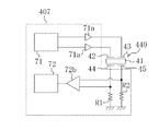
そして、制御装置407は、第1及び第2マイナス側電極層44,45にそれぞれ直列に接続された第1及び第2検出抵抗R1,R2の検出抵抗電圧の差をアンプ72bで増幅して検出することで、第1及び第2検出抵抗R1,R2に流れる通電電流の差の変化を検出している。   Then, the control device 407 detects the difference between the detection resistance voltages of the first and second detection resistors R1 and R2 connected in series to the first and second negative electrode layers 44 and 45 by the amplifier 72b. By doing so, a change in the difference between the energization currents flowing through the first and second detection resistors R1, R2 is detected.

ここで、第1プラス側及び第1マイナス側電極層42,44と第2プラス側及び第2マイナス側電極層43,45とは、図3に示すように、圧電体層41の主面の異なる対角線方向に位置するため、一方の駆動子49(図3の左側)の接触圧力の変化の影響は、第1電極42a,44aを有する第1プラス側及び第1マイナス側電極層42,44で挟持された部分の圧電体層41が受け易く、他方の駆動子49(図3の右側)の接触圧力の変化の影響は、第2電極43b,45bを有する第2プラス側及び第2マイナス側電極層43,45で挟持された部分の圧電体層41が受け易い。そのため、第1プラス側及び第1マイナス側電極層42,44と第2プラス側及び第2マイナス側電極層43,45とで影響を受け易い駆動子49が異なっており、第1及び第2検出抵抗R1,R2に流れる通電電流の差を検出することによって、一方の駆動子49と他方の駆動子49とに作用する接触圧力の微妙な差も検出することができる。その結果、ステージ11の位置をより詳細に推定することができる。   Here, the first plus side and first minus side electrode layers 42 and 44 and the second plus side and second minus side electrode layers 43 and 45 are formed on the main surface of the piezoelectric layer 41 as shown in FIG. Since they are located in different diagonal directions, the influence of the change in the contact pressure of one driver 49 (left side in FIG. 3) is that the first plus side electrode layers 42, 44 having the first electrodes 42a, 44a are affected. The piezoelectric layer 41 in the portion sandwiched between the two is easily received, and the influence of the change in the contact pressure of the other driver 49 (right side in FIG. 3) is caused by the second plus side and the second minus side having the second electrodes 43b and 45b. A portion of the piezoelectric layer 41 sandwiched between the side electrode layers 43 and 45 is easily received. Therefore, the first positive side and first negative side electrode layers 42 and 44 and the second positive side and second negative side electrode layers 43 and 45 have different driver elements 49, which are different from each other. By detecting the difference between the energization currents flowing through the detection resistors R1 and R2, it is possible to detect a subtle difference in contact pressure acting on one driver 49 and the other driver 49. As a result, the position of the stage 11 can be estimated in more detail.

《その他の実施形態》
本発明は、前記実施形態1〜4について、以下のような構成としてもよい。
<< Other Embodiments >>
This invention is good also as following structures about the said Embodiment 1-4.

すなわち、前記実施形態では、超音波アクチュエータ2を、アクチュエータ本体4に長手方向への縦振動の1次モードと屈曲振動の2次モードとを調和的に発生させるように構成したが、これに限られるものではない。これ以外の振動又はモードを発生させるものであってもよく、アクチュエータ本体4を振動させて駆動子49,49とステージ11との間の摩擦力を介して駆動力を出力する振動型アクチュエータであれば任意の構成を採用することができる。   That is, in the above-described embodiment, the ultrasonic actuator 2 is configured to generate the longitudinal mode of the longitudinal vibration and the secondary mode of the bending vibration in the actuator body 4 in a harmonic manner. It is not something that can be done. Other vibrations or modes may be generated, and any vibration type actuator that vibrates the actuator body 4 and outputs a driving force via a frictional force between the driving elements 49 and 49 and the stage 11 may be used. Any configuration can be adopted.

また、超音波アクチュエータ2は、前記の構成に限られるものではない。例えば、前記支持ゴム61,61及び付勢ゴム62を介して圧電素子ユニット40に給電する構成ではなく、リード線を圧電素子ユニット40に接続して給電する構成でもよい。また、圧電素子ユニット40の振動のノード部(節の部分)を非弾性部材で支持する構成であってもよい。さらには、図17に示すように、圧電素子ユニット40の一方の短辺側面に1つの駆動子49が設けられた超音波アクチュエータ502を採用してもよい。かかる構成であっても、圧電素子ユニット40が長手方向への縦振動の1次モードと屈曲振動の2次モードとの合成振動を行うことによって駆動子49が周回運動を行い、ステージ11との間の摩擦力を介して、該ステージ11を所定の可動方向(短手方向と平行な方向)へ移動させることができる。さらにまた、アクチュエータ本体4は圧電素子ユニット40で構成されているが、金属などの基板に圧電素子を貼り付けた構成や、金属などで共振器を形成し、圧電素子を挟み込んだ構成であってもよい。この場合、圧電素子を含んで構成された共振器がアクチュエータ本体を構成する。   Further, the ultrasonic actuator 2 is not limited to the above configuration. For example, a configuration in which power is supplied to the piezoelectric element unit 40 via the support rubbers 61 and 61 and the urging rubber 62 may be used instead of supplying power to the piezoelectric element unit 40. Moreover, the structure which supports the node part (node part) of the vibration of the piezoelectric element unit 40 with an inelastic member may be sufficient. Furthermore, as shown in FIG. 17, an ultrasonic actuator 502 in which one driver element 49 is provided on one short side surface of the piezoelectric element unit 40 may be employed. Even in such a configuration, the piezoelectric element unit 40 performs the combined vibration of the primary mode of the longitudinal vibration in the longitudinal direction and the secondary mode of the bending vibration, so that the driving element 49 performs the circular motion, and the stage 11 The stage 11 can be moved in a predetermined movable direction (a direction parallel to the short side direction) via the frictional force therebetween. Furthermore, the actuator body 4 is composed of the piezoelectric element unit 40. The actuator body 4 has a structure in which a piezoelectric element is attached to a substrate such as a metal, or a structure in which a resonator is formed with a metal or the like and the piezoelectric element is sandwiched between them. Also good. In this case, the resonator including the piezoelectric element constitutes the actuator body.

さらに、前記実施形態では、超音波アクチュエータ2を基台に固定すると共に、駆動子49,49を移動可能なステージ11に当接させて、該超音波アクチュエータ2を作動させることで該ステージ11を駆動させているが、図18に示すように、超音波アクチュエータ2をステージに固定する構成としてもよい。詳しくは、駆動装置601は、互いに平行な状態で基台に固定されたガイド13,13と、該ガイド13,13に摺動自在に取り付けられたステージ14と、超音波アクチュエータ2とを備えている。該ガイド13,13のうちの一方のガイド13には、該ガイド13に固定された当接部材13aが設けられている。一方、ステージ14には、アクチュエータ取付部14aが設けられている。そして、超音波アクチュエータ2は、駆動子49,49が該ガイド13の当接部材13aに当接する状態で、該ステージ14のアクチュエータ取付部14aにケース5が取り付けられている。この状態で、超音波アクチュエータ2を作動させると、駆動子49,49は当接部材13aに対して駆動力を出力するが、該当接部材13aは固定されているため、超音波アクチュエータ2自体が当接部材13aに対して相対的にガイド13,13の長手方向に振動する。その結果、アクチュエータ取付部14aを介してケース5と連結されたステージ14がガイド13,13の長手方向に駆動される。このとき、当接部材13aにおける、駆動子49,49が接触する面には凹凸部15が形成されている。この凹凸部15は、ステージ14の可動方向に沿って周期的に配列された凹部15aと凸部15bとで構成されている。この凹凸部15は、図18においては、実施形態1と同様に形成されているが、実施形態2又は3の凹凸部と同様に形成されてもよい。   Further, in the above-described embodiment, the ultrasonic actuator 2 is fixed to the base, and the driver elements 49 and 49 are brought into contact with the movable stage 11 so that the ultrasonic actuator 2 is operated. Although driven, the ultrasonic actuator 2 may be fixed to the stage as shown in FIG. Specifically, the drive device 601 includes guides 13 and 13 fixed to a base in a parallel state, a stage 14 slidably attached to the guides 13 and 13, and the ultrasonic actuator 2. Yes. One guide 13 of the guides 13 and 13 is provided with a contact member 13 a fixed to the guide 13. On the other hand, the stage 14 is provided with an actuator mounting portion 14a. In the ultrasonic actuator 2, the case 5 is attached to the actuator attachment portion 14 a of the stage 14 in a state where the driver elements 49 are in contact with the contact member 13 a of the guide 13. When the ultrasonic actuator 2 is operated in this state, the driver elements 49 and 49 output a driving force to the contact member 13a. However, since the corresponding contact member 13a is fixed, the ultrasonic actuator 2 itself The guides 13 and 13 vibrate in the longitudinal direction relative to the contact member 13a. As a result, the stage 14 connected to the case 5 via the actuator mounting portion 14a is driven in the longitudinal direction of the guides 13 and 13. At this time, the concavo-convex portion 15 is formed on the surface of the contact member 13a on which the driver elements 49 come into contact. The concavo-convex portion 15 includes a concave portion 15 a and a convex portion 15 b that are periodically arranged along the movable direction of the stage 14. In FIG. 18, the uneven portion 15 is formed in the same manner as in the first embodiment, but may be formed in the same manner as the uneven portion in the second or third embodiment.

さらにまた、前記実施形態では、ステージの位置検出の全てを、ステージの凹凸部に起因する駆動子49,49の接触圧力の変化に基づいて行っているが、これに限られるものではない。すなわち、前記実施形態におけるステージの凹凸部に起因する駆動子49,49の接触圧力の変化に基づくステージの位置検出と、別途設けた位置検出センサによるステージの位置検出とを組み合わせてもよい。例えば、実施形態3に係る凹凸部312のように位置情報を有する凹凸部を特定の位置に形成し、凹凸部と凹凸部との間の位置検出は別途設けた位置検出センサで行う構成としてもよい。こうすることで、ステージの位置検出の全てを別途も受けた位置検出センサで行う構成と比べて、別付けの位置検出センサを可及的に省略することができ、駆動装置の大型化を防止しつつ、簡易な構成でステージの位置検出を実現することができる。   Furthermore, in the above-described embodiment, all the position detection of the stage is performed based on the change in the contact pressure of the driver elements 49 due to the uneven portion of the stage, but this is not restrictive. That is, the position detection of the stage based on the change in the contact pressure of the driving elements 49 and 49 caused by the uneven portions of the stage in the embodiment may be combined with the position detection of the stage by a separately provided position detection sensor. For example, an uneven part having position information such as the uneven part 312 according to the third embodiment is formed at a specific position, and the position detection between the uneven part and the uneven part is performed by a separately provided position detection sensor. Good. In this way, a separate position detection sensor can be omitted as much as possible, compared to a configuration in which a position detection sensor that receives all of the stage position detection separately is used, thereby preventing an increase in the size of the drive device. However, the position of the stage can be detected with a simple configuration.

また、前記実施形態では、圧電素子ユニット40の反共振周波数近傍の交流電圧によって超音波アクチュエータ2を作動させているが、これに限られるものではない。すなわち、それ以外の周波数の交流電圧によって超音波アクチュエータ2を作動させる場合であっても、その周波数における圧電素子ユニット40のインピーダンスと与圧との関係を予め求めておけば、圧電素子ユニット40のインピーダンスの変化(あるいは、検出抵抗Rの通電電流)から駆動子49の接触圧力を求めることができ、ステージの位置を検出することができる。   Moreover, in the said embodiment, although the ultrasonic actuator 2 is operated with the alternating voltage near the antiresonance frequency of the piezoelectric element unit 40, it is not restricted to this. That is, even when the ultrasonic actuator 2 is operated by an AC voltage of other frequency, if the relationship between the impedance of the piezoelectric element unit 40 and the pressurization at that frequency is obtained in advance, the piezoelectric element unit 40 The contact pressure of the driver 49 can be obtained from the change in impedance (or the energization current of the detection resistor R), and the position of the stage can be detected.

さらに、圧電素子ユニット40のインピーダンスの変化は、検出抵抗Rの通電電流の変化に基づいてのみ求められるものではない。例えば、定電流駆動回路で圧電素子ユニット40を作動させると共に、検出抵抗Rの電圧の変化に基づいて圧電素子ユニと40のインピーダンスを求めることも可能である。その他、圧電素子ユニット40のインピーダンスの変化を求めることができる構成であれば、任意の構成を採用することができる。   Furthermore, the change in the impedance of the piezoelectric element unit 40 is not obtained only based on the change in the energization current of the detection resistor R. For example, it is possible to operate the piezoelectric element unit 40 with a constant current drive circuit and obtain the impedance of the piezoelectric element uni and 40 based on a change in the voltage of the detection resistor R. In addition, any configuration can be adopted as long as the change in impedance of the piezoelectric element unit 40 can be obtained.

尚、以上の実施形態は、本質的に好ましい例示であって、本発明、その適用物、あるいはその用途の範囲を制限することを意図するものではない。   In addition, the above embodiment is an essentially preferable illustration, Comprising: It does not intend restrict | limiting the range of this invention, its application thing, or its use.

以上説明したように、本発明は、振動型アクチュエータによって可動体を固定体に対して相対的に移動させる駆動装置について有用である。   As described above, the present invention is useful for a drive device that moves a movable body relative to a fixed body by a vibration type actuator.

本発明の実施形態1に係る駆動装置の概略正面図である。It is a schematic front view of the drive device concerning Embodiment 1 of the present invention. 駆動装置の斜視図である。It is a perspective view of a drive device. 超音波アクチュエータの斜視図である。It is a perspective view of an ultrasonic actuator. 圧電素子ユニットの分解斜視図である。It is a disassembled perspective view of a piezoelectric element unit. アクチュエータ本体の概略構成を示す概略正面図である。It is a schematic front view which shows schematic structure of an actuator main body. アクチュエータ本体の長手方向への縦振動の1次モードによる変位を示す概念図である。It is a conceptual diagram which shows the displacement by the primary mode of the longitudinal vibration to the longitudinal direction of an actuator main body. アクチュエータ本体の屈曲振動の2次モードによる変位を示す概念図である。It is a conceptual diagram which shows the displacement by the secondary mode of the bending vibration of an actuator main body. アクチュエータ本体の動作を示す概念図である。It is a conceptual diagram which shows operation | movement of an actuator main body. 制御装置の構成を示すブロック図である。It is a block diagram which shows the structure of a control apparatus. 超音波アクチュエータによるステージの駆動を説明するための概念図であって、(a)は駆動前の状態、(b)はアクチュエータ本体が長手方向に伸張することで一方の駆動子によってステージを駆動する状態、(c)はアクチュエータ本体が長手方向に収縮することで他方の駆動子によってステージを駆動する状態を示す。It is a conceptual diagram for demonstrating the drive of the stage by an ultrasonic actuator, Comprising: (a) is the state before a drive, (b) drives a stage by one driver, when an actuator main body expand | extends to a longitudinal direction. State (c) shows a state in which the stage is driven by the other driver as the actuator body contracts in the longitudinal direction. 圧電素子ユニットの駆動周波数とインピーダンスとの関係を示すグラフである。It is a graph which shows the relationship between the drive frequency and impedance of a piezoelectric element unit. ステージの移動距離と電流検出部によって検出された電流値との関係を示すグラフである。It is a graph which shows the relationship between the moving distance of a stage, and the electric current value detected by the electric current detection part. 実施形態2に係る駆動装置の概略正面図である。FIG. 5 is a schematic front view of a drive device according to a second embodiment. 実施形態3に係る駆動装置の概略正面図である。FIG. 6 is a schematic front view of a drive device according to a third embodiment. 実施形態4に係る制御装置の構成を示すブロック図である。It is a block diagram which shows the structure of the control apparatus which concerns on Embodiment 4. 圧電素子ユニットの分解斜視図である。It is a disassembled perspective view of a piezoelectric element unit. その他の実施形態に係る超音波アクチュエータの斜視図である。It is a perspective view of the ultrasonic actuator concerning other embodiments. その他の実施形態に係る駆動装置の斜視図である。It is a perspective view of the drive device concerning other embodiments.

符号の説明Explanation of symbols

1 駆動装置
11 ステージ(可動体)
12 凹凸部
13 ガイド(固定体)
14 ステージ(可動体)
2 超音波アクチュエータ(振動型アクチュエータ)
49 駆動子
7 制御装置(制御部)
1 Driving device 11 Stage (movable body)
12 Concavity and convexity 13 Guide (fixed body)
14 stage (movable body)
2 Ultrasonic actuator (vibration actuator)
49 Driver 7 Controller (Control Unit)

Claims (4)

固定体と、該固定体に対して相対的に移動可能な可動体と、圧電素子を用いて構成され該可動体を移動させる振動型アクチュエータと、該圧電素子に給電することによって振動型アクチュエータを制御する制御部とを備えた駆動装置であって、
前記振動型アクチュエータは、前記可動体の移動方向に間隔を空けて2つ設けられ且つ前記可動体及び前記固定体のうちの一方に接触する駆動子を有すると共に、該可動体及び固定体のうちの他方に取り付けられており、
前記可動体及び固定体のうちの一方における前記駆動子が接触する面には、凹凸部が形成されており、
前記圧電素子は、少なくとも1つの圧電体と、該圧電体層を挟持するように設けられた第1及び第2電極とを有し、
前記第1電極は、前記2つの駆動子のうちの一方の駆動子に近接して設けられ、
前記第2電極は、前記2つの駆動子のうちの他方の駆動子に近接して設けられ、
前記制御部は、前記第1及び第2電極に流れる電流に基づいて、前記一方の駆動子の接触圧力と前記他方の駆動子の接触圧力との差を検出し、前記駆動子の接触圧力の変化に基づいて前記可動体の位置を検出する駆動装置。
A fixed body, a movable body movable relative to the fixed body, a vibration type actuator configured to move the movable body using a piezoelectric element, and a vibration type actuator by supplying power to the piezoelectric element A drive device comprising a control unit for controlling,
The vibration-type actuator has two drive elements spaced apart in the moving direction of the movable body and has a driver that contacts one of the movable body and the fixed body. Attached to the other of
An uneven portion is formed on the surface of the movable body and the fixed body on which the driver element contacts,
The piezoelectric element has at least one piezoelectric body, and first and second electrodes provided so as to sandwich the piezoelectric layer,
The first electrode is provided in proximity to one of the two driver elements,
The second electrode is provided close to the other driver of the two drivers,
The control unit detects a difference between the contact pressure of the one driver element and the contact pressure of the other driver element based on the current flowing through the first and second electrodes, and determines the contact pressure of the driver element. A drive device that detects the position of the movable body based on a change.
前記凹凸部の周期は、前記駆動子の間隔よりも長い請求項1に記載の駆動装置。   The driving device according to claim 1, wherein a period of the uneven portion is longer than an interval between the driving elements. 前記凹凸部の幅は、前記駆動子の間隔よりも狭い請求項1に記載の駆動装置。   The driving device according to claim 1, wherein a width of the uneven portion is narrower than an interval between the driving elements. 固定体と、該固定体に対して相対的に移動可能な可動体と、圧電素子を用いて構成され該可動体を移動させる振動型アクチュエータと、該圧電素子に給電することによって振動型アクチュエータを制御する制御部とを備えた駆動装置であって、
前記振動型アクチュエータは、前記可動体及び前記固定体のうち一方に接触する駆動子を有すると共に、該可動体及び固定体のうち他方に取り付けられており、
前記可動体及び固定体のうちの一方における前記駆動子が接触する面には、凹凸部が形成されており、
前記凹凸部の配置又は形状は、該凹凸部が形成された面に沿った位置に応じて変化しており、
前記圧電素子は、少なくとも1つの圧電体と、該圧電体層を挟持するように設けられた第1及び第2電極とを有し、
前記第1電極は、前記2つの駆動子のうちの一方の駆動子に近接して設けられ、
前記第2電極は、前記2つの駆動子のうちの他方の駆動子に近接して設けられ、
前記制御部は、前記第1及び第2電極に流れる電流に基づいて、前記一方の駆動子の接触圧力と前記他方の駆動子の接触圧力との差を検出し、前記駆動子の接触圧力の変化に基づいて前記可動体の位置を検出する駆動装置。
A fixed body, a movable body movable relative to the fixed body, a vibration type actuator configured to move the movable body using a piezoelectric element, and a vibration type actuator by supplying power to the piezoelectric element A drive device comprising a control unit for controlling,
The vibration type actuator has a driver that contacts one of the movable body and the fixed body, and is attached to the other of the movable body and the fixed body,
An uneven portion is formed on the surface of the movable body and the fixed body on which the driver element contacts,
The arrangement or shape of the concavo-convex portion is changed according to the position along the surface on which the concavo-convex portion is formed,
The piezoelectric element has at least one piezoelectric body, and first and second electrodes provided so as to sandwich the piezoelectric layer,
The first electrode is provided in proximity to one of the two driver elements,
The second electrode is provided close to the other driver of the two drivers,
The control unit detects a difference between the contact pressure of the one driver element and the contact pressure of the other driver element based on the current flowing through the first and second electrodes, and determines the contact pressure of the driver element. A drive device that detects the position of the movable body based on a change.
JP2007122574A 2007-05-07 2007-05-07 Drive device Expired - Fee Related JP5201873B2 (en)

Priority Applications (2)

Application Number Priority Date Filing Date Title
JP2007122574A JP5201873B2 (en) 2007-05-07 2007-05-07 Drive device
US12/114,891 US7679265B2 (en) 2007-05-07 2008-05-05 Drive unit

Applications Claiming Priority (1)

Application Number Priority Date Filing Date Title
JP2007122574A JP5201873B2 (en) 2007-05-07 2007-05-07 Drive device

Publications (3)

Publication Number Publication Date
JP2008278720A JP2008278720A (en) 2008-11-13
JP2008278720A5 JP2008278720A5 (en) 2010-06-24
JP5201873B2 true JP5201873B2 (en) 2013-06-05

Family

ID=39968888

Family Applications (1)

Application Number Title Priority Date Filing Date
JP2007122574A Expired - Fee Related JP5201873B2 (en) 2007-05-07 2007-05-07 Drive device

Country Status (2)

Country Link
US (1) US7679265B2 (en)
JP (1) JP5201873B2 (en)

Families Citing this family (10)

* Cited by examiner, † Cited by third party
Publication number Priority date Publication date Assignee Title
JP5184811B2 (en) * 2007-05-07 2013-04-17 パナソニック株式会社 Vibration type actuator
JP4977202B2 (en) * 2007-07-12 2012-07-18 パナソニック株式会社 Vibrating actuator and drive device including the same
JP2009117559A (en) * 2007-11-05 2009-05-28 Olympus Corp Multilayer piezoelectric element and ultrasonic motor
DE102008053646A1 (en) * 2008-10-29 2010-05-06 Minebea Co., Ltd. Linear drive with shock compensation
JP2010130889A (en) * 2008-12-01 2010-06-10 Olympus Corp Linear driving type ultrasonic motor
JP5142974B2 (en) * 2008-12-19 2013-02-13 オリンパス株式会社 Switching mechanism by ultrasonic transducer
JP2011015552A (en) * 2009-07-02 2011-01-20 Panasonic Corp Drive device
US11533011B2 (en) * 2020-03-04 2022-12-20 Qualcomm Incorporated Actuator driver circuit with self-resonance tracking
CN113675328B (en) * 2020-05-14 2024-03-15 中芯集成电路(宁波)有限公司 Piezoelectric driver, manufacturing method thereof and imaging module
CN120324805A (en) * 2025-06-23 2025-07-18 上海爱申科技发展股份有限公司 Transrectal ultrasound therapy system for prostatitis

Family Cites Families (10)

* Cited by examiner, † Cited by third party
Publication number Priority date Publication date Assignee Title
DE69109164T2 (en) * 1990-03-23 1996-01-04 Rockwell International Corp Piezoelectric motor.
JP2966590B2 (en) 1991-07-25 1999-10-25 松下電工株式会社 Linear drive type piezoelectric motor
JP4476409B2 (en) * 2000-01-26 2010-06-09 セイコーインスツル株式会社 Electronics
JP2002374686A (en) 2001-06-14 2002-12-26 Nikon Corp Vibration actuator control device
US6664711B2 (en) * 2001-08-23 2003-12-16 Delphi Technologies, Inc. Harmonic motor
US6897598B2 (en) * 2002-03-15 2005-05-24 Kyocera Corporation Ultrasonic motor and guide apparatus having the same as driving source of movable body
US6798117B2 (en) * 2002-07-10 2004-09-28 Piezomotor Uppsala Ab Fine control of electromechanical motors
US7161278B2 (en) * 2003-10-31 2007-01-09 Piezomotor Uppsala Ab Peristaltic electromechanical actuator
JP4576214B2 (en) * 2004-11-26 2010-11-04 オリンパスイメージング株式会社 Ultrasonic motor and lens barrel
JP4586754B2 (en) * 2005-06-29 2010-11-24 セイコーエプソン株式会社 Piezoelectric actuator drive amount detection device and electronic device

Also Published As

Publication number Publication date
US20080278037A1 (en) 2008-11-13
JP2008278720A (en) 2008-11-13
US7679265B2 (en) 2010-03-16

Similar Documents

Publication Publication Date Title
JP5201873B2 (en) Drive device
JP5264273B2 (en) Drive device
JP4209464B2 (en) Ultrasonic actuator device
CN102270941B (en) Control device of vibration type actuator and control method of vibration type actuator
JP5127293B2 (en) Drive device
JP4794897B2 (en) Ultrasonic motor
JP5277010B2 (en) Drive device
JP4209465B2 (en) Drive device
JP2006503529A5 (en)
JP2006503529A (en) High resolution piezoelectric motor
JP4679938B2 (en) Ultrasonic motor
JP4795162B2 (en) Ultrasonic motor and vibration detection method of ultrasonic motor
JP4814948B2 (en) Control device for vibration actuator
JP2006094591A (en) Ultrasonic motor and its operation method
JP4795158B2 (en) Ultrasonic motor
JP2008236820A (en) Driving device
JP5315434B2 (en) Drive device
JP5733966B2 (en) Vibration type driving device
JP2015144557A (en) Ultrasonic motor drive control method and ultrasonic motor drive control apparatus
JP5486256B2 (en) Ultrasonic motor
JP2005102368A (en) Drive device
JP2006246660A (en) Ultrasonic motor and ultrasonic motor system
JP2010004625A (en) Piezoelectric vibrator and method of driving the same
JP2006304425A (en) Operation method of ultrasonic motor
JP2010279152A (en) Ultrasonic motor drive device

Legal Events

Date Code Title Description
A521 Request for written amendment filed

Free format text: JAPANESE INTERMEDIATE CODE: A523

Effective date: 20100506

A621 Written request for application examination

Free format text: JAPANESE INTERMEDIATE CODE: A621

Effective date: 20100506

RD02 Notification of acceptance of power of attorney

Free format text: JAPANESE INTERMEDIATE CODE: A7422

Effective date: 20120124

A977 Report on retrieval

Free format text: JAPANESE INTERMEDIATE CODE: A971007

Effective date: 20120330

A131 Notification of reasons for refusal

Free format text: JAPANESE INTERMEDIATE CODE: A131

Effective date: 20120403

A521 Request for written amendment filed

Free format text: JAPANESE INTERMEDIATE CODE: A523

Effective date: 20120601

TRDD Decision of grant or rejection written
A01 Written decision to grant a patent or to grant a registration (utility model)

Free format text: JAPANESE INTERMEDIATE CODE: A01

Effective date: 20130129

A61 First payment of annual fees (during grant procedure)

Free format text: JAPANESE INTERMEDIATE CODE: A61

Effective date: 20130212

R150 Certificate of patent or registration of utility model

Ref document number: 5201873

Country of ref document: JP

Free format text: JAPANESE INTERMEDIATE CODE: R150

Free format text: JAPANESE INTERMEDIATE CODE: R150

FPAY Renewal fee payment (event date is renewal date of database)

Free format text: PAYMENT UNTIL: 20160222

Year of fee payment: 3

LAPS Cancellation because of no payment of annual fees