JP5240177B2 - Disconnector - Google Patents
Disconnector Download PDFInfo
- Publication number
- JP5240177B2 JP5240177B2 JP2009273569A JP2009273569A JP5240177B2 JP 5240177 B2 JP5240177 B2 JP 5240177B2 JP 2009273569 A JP2009273569 A JP 2009273569A JP 2009273569 A JP2009273569 A JP 2009273569A JP 5240177 B2 JP5240177 B2 JP 5240177B2
- Authority
- JP
- Japan
- Prior art keywords
- contact
- electrode
- movable
- resistor
- disconnector
- Prior art date
- Legal status (The legal status is an assumption and is not a legal conclusion. Google has not performed a legal analysis and makes no representation as to the accuracy of the status listed.)
- Active
Links
Images


Landscapes
- Arc-Extinguishing Devices That Are Switches (AREA)
Description
この発明は、小電流の遮断を行う機能を有する断路器に関する。 The present invention relates to a disconnector having a function of cutting off a small current.
従来の断路器においては、可動電極を、軸方向に、金属部分、抵抗体および別の金属部分の三部分の棒状の連続体で構成し、可動電極に電流を導入する接触子を別の金属部に摺動接触させ、開極時に再点弧が発生する場合には、可動電極の先端側の金属部分にアークを点弧させて抵抗体を通じて電流が流れるようにしたので、再点弧により発生するサージを抑制することができる。また、可動電極の投入状態では、短絡電極にて金属部分と別の金属部分を電気的に接続することで抵抗体を短絡し、抵抗体が回路に挿入されないようにしている(例えば、特許文献1参照)。 In the conventional disconnector, the movable electrode is constituted by a three-part rod-shaped continuous body of a metal part, a resistor and another metal part in the axial direction, and a contact for introducing a current into the movable electrode is made of another metal. When a re-ignition occurs at the time of opening, the arc is ignited at the tip of the movable electrode so that the current flows through the resistor. The generated surge can be suppressed. In addition, in a state where the movable electrode is put in, the resistor is short-circuited by electrically connecting the metal portion and another metal portion with a short-circuit electrode so that the resistor is not inserted into the circuit (for example, Patent Documents). 1).
従来の断路器では、可動電極が軸方向に、金属部分、抵抗体および別の金属部分の三部分の棒状の連続体で構成され、上記連続体の外周部のそれぞれ異なる部分と摺動接触する接触子と短絡電極とが設けられていた。そのため、可動電極が長くなると共に、短絡電極を構成する部品とそれを収納する空間分だけ寸法が大きくなっていた。また、開閉極動作において、接触子に加えて短絡電極を可動電極と摺動させる必要があったため、摺動にともなう摩擦抵抗が高くなり、開閉操作力を大きくする必要があった。つまり、従来の断路器では、抵抗体にてサージを抑制するために装置が大形化するという問題があった。 In the conventional disconnector, the movable electrode is composed of a rod-like continuous body of three parts, a metal part, a resistor, and another metal part in the axial direction, and is in sliding contact with different parts of the outer peripheral part of the continuous body. A contact and a short-circuit electrode were provided. Therefore, the length of the movable electrode is increased, and the size of the component constituting the short-circuit electrode and the space for storing the component are increased. In addition, in the opening / closing pole operation, since it is necessary to slide the short-circuit electrode with the movable electrode in addition to the contact, the frictional resistance accompanying sliding increases, and the opening / closing operation force must be increased. That is, in the conventional disconnector, there is a problem that the device is increased in size in order to suppress the surge by the resistor.
この発明は、上記のような問題点を解決するためになされたものであり、開閉極動作時のサージを抑制できる小形の断路器を得ることを目的としている。 The present invention has been made to solve the above-described problems, and an object of the present invention is to obtain a small disconnector that can suppress a surge during switching pole operation.
この発明に係る断路器は、固定された接触子との摺動接触により電流が導入される可動電極を、固定電極に接離させることで電力回路を開閉路する断路器であって、上記可動電極は、開閉極動作の方向に中心軸を有して先端部で上記固定電極と接離する棒状の可動導体と、上記可動導体の側部の一部外周面を覆う筒状の抵抗体とを有している。上記筒状の抵抗体は、上記開閉極動作により、少なくとも上記可動電極が、上記可動電極と上記固定電極の間に印加されている電圧に対して絶縁が維持される位置から、上記固定電極に接触を開始する位置まで移動する間、上記接触子の摺動接触部と上記可動導体との間に挿入される。さらに、上記抵抗体は、上記可動電極が上記接触を開始する位置よりさらに上記固定電極側に移動した閉路状態では、上記摺動接触部と上記可動導体との間に挿入されないように配置されたものである。 The disconnector according to the present invention is a disconnector that opens and closes a power circuit by moving a movable electrode into which a current is introduced by sliding contact with a fixed contact to and from a fixed electrode. The electrode includes a rod-shaped movable conductor having a central axis in the direction of the opening / closing pole operation and contacting and separating from the fixed electrode at the tip, and a cylindrical resistor covering a part of the outer peripheral surface of the side of the movable conductor have. The cylindrical resistor is formed on the fixed electrode from a position where at least the movable electrode is insulated from the voltage applied between the movable electrode and the fixed electrode by the switching pole operation. While moving to the position to start contact, the contact is inserted between the sliding contact portion of the contact and the movable conductor. Further, the resistor is disposed so as not to be inserted between the sliding contact portion and the movable conductor in a closed state where the movable electrode is further moved to the fixed electrode side from a position where the movable electrode starts the contact. Is.
この発明によれば、開閉極動作時のサージを抑制できる小形の断路器を得ることができる。 According to the present invention, it is possible to obtain a small disconnector that can suppress a surge during switching pole operation.
実施の形態1.
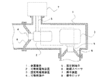
図1は、この発明の実施の形態1による断路器の金属筐体1などの断面を取って内部構造を示す図である。金属筐体1の内部には、可動側電極装置2および固定側電極装置3が、それぞれ可動側端子4および固定側端子5を介して絶縁スペーサ6に固定されている。金属筐体1の外部に固定された操作装置7の操作力は、操作ロッド8にて可動側電極装置2へと伝達される。金属筐体1の内部は、絶縁ガス、例えば空気、SF6ガス、および窒素などが満たされている。図2は、図1の一点差線で囲まれた消弧室の主要部を示す断面図であり、開路状態となっている。また、図3は、閉路状態の上記主要部を示している。
Embodiment 1 FIG.
FIG. 1 is a view showing an internal structure by taking a cross section of a metal casing 1 and the like of a disconnector according to Embodiment 1 of the present invention. Inside the metal housing 1, a
可動電極9は、開閉極動作方向に中心軸を有する棒状をしており、操作装置7による操作ロッド8の回転動作を、ラック・アンド・オピニオンなどにより直線運動に変換させることによって、閉極動作時は図2の右方向に、開極動作時は図3の左方向に駆動される。閉路状態においては、可動電極9の先端部は、固定電極9を構成する固定アーク電極11と固定主電極12との両方に接触している。固定側シールド13は、固定アーク電極11と固定主電極12を取り囲むように配置され、固定電極9側の電界集中を緩和する役割をもつ。電流は、棒状の可動電極9の側部にて摺動可能に接触している接触子14から、可動電極9に導入される。この接触子14は、図には示されていない断路器本体構造に固定されている。可動側シールド15は、可動電極9と接触子14を取り囲むように配置され、可動電極9側の電界集中を緩和する役割をもつ。
The
図4に、可動電極9の断面図を示す。可動電極9は、開閉極動作方向に中心軸を有する棒状の可動導体16と、可動導体16の側部の一部外周面を覆うように固着された中空円筒形状の抵抗体17とを有しており、さらに抵抗体17の外周面、つまり接触子14の側の面に金属板18が取り付けられている。抵抗体17は、例えば、銅ニッケル合金、銅マンガン合金、およびニッケルクロム合金などの金属合金系の抵抗体、又はセラミクスと金属との焼結系の抵抗体などが用いられる。金属板18の固定電極10と反対側の端面は絶縁体19に接し、金属板18の固定電極10側の端面は抵抗体17に接しており、可動導体16と金属板18が直接接触しないように構成されている。金属板18の接触子14との摺動面は、抵抗体17よりも摺動時の抗力が小さくなるように材料および表面粗さ設定されている。また、絶縁体19も、抵抗体17よりも摺動時の抗力が小さくなるように材料および表面粗さ設定されていると共に、絶縁体19の上記中心軸方向の長さは接触子14の摺動接触部14a(接触面)の上記中心軸方向の長さよりも短くしてある。
FIG. 4 shows a cross-sectional view of the
抵抗体17の上記中心軸の方向の位置は、図3に示すように、閉路状態で接触子14が抵抗体17に接触しないように配置されており、接触子14は、直接、可動導体16と接触する。従って、閉路状態においては、通電電流は、図3中に矢印で示すように、抵抗値が高い抵抗体17を避けて接触子14から可動導体16の中心軸付近を固定主電極12の方へ流れていく。また、開閉極動作の途中においては、金属板18が接触子14と直接的に接触し摺動するので、電流は、接触子14から金属板18を介して抵抗体17へ流れ、さらに抵抗体17から可動導体16へと流れる。
As shown in FIG. 3, the position of the
次に、この発明の断路器の閉極動作について説明する。開路状態である図2の状態から、操作装置7によって可動電極9が図2の右方向に動作を開始し、接触子14と抵抗体17が接触するようになる。固定アーク電極11と可動電極9の両極間の距離が、閉極動作が進むにつれて短くなることにより両極間に印加されている電圧に対して極間の絶縁が耐えることができなくなり、図5に示すように、可動電極9の先端部と固定電極9の固定アーク電極11に間でアークが発弧する。さらに、アークの発弧に起因して、閉極動作時のサージ(以下、投入サージ)が断路器を接続している回路において発生する。断路器の開閉極動作時のサージは商用周波数の幾サイクルにわたって継続して発生する。投入サージは電力回路においては過電圧となり、サージ抑制手段を有しない断路器では極めて大きな過電圧が発生する場合があり、この過電圧により電力機器に絶縁上の問題が発生することがある(「電気協同研究第57巻第3号」電気協同研究会編、平成14年発刊、第2章、2―2項、参照)。この発明の断路器では、図5に示すように、アークが発弧する可動電極9の位置において、接触子14の摺動接触部14aと可動導体16との間に金属板18が固着した抵抗体17が挿入されるので、サージの電流が抵抗体17を通して流れて減衰し、過電圧を抑制することができる。
Next, the closing operation of the disconnector of the present invention will be described. From the state shown in FIG. 2, which is an open circuit state, the
閉極動作が進み、図6に示すように、可動導体16の先端部が固定アーク電極11と接触するようになると、もはやアークは発生しなくなるため投入サージも発生しない。可動導体16の先端部の接触後、さらに閉極動作が進み、図7の状態になったときに、接触子14が金属板18から離れ始める。前述のように絶縁体19の上記中心軸の方向の長さは接触子14の接触面の上記中心軸方向の長さより短くなっているので、接触子14は金属板18と可動導体16とに同時に接触できるので、電気的に絶縁状態になることはない。
When the closing operation proceeds and the tip of the
さらに閉極動作が進み、可動電極9が固定主電極12に接触するようになったとき、あるいは、可動電極9が固定主電極12に接触する直前に、抵抗体17と接触子14とが離れ、接触子14が、直接、可動導体16に接触するようになり、図3に示すような閉路状態に到る。
When the closing operation further proceeds and the
このように、この実施の形態で示した断路器では、閉極動作の途中のアークが発生する可動電極9の位置において、抵抗体17を回路に挿入できるので、投入サージを抑制することができる。尚、上記の説明では閉極動作時を取り上げて説明したが、開極動作時においても印加される電圧が交流の場合や、進み小電流遮断時のように変動する電圧が印加されるなどして、開極初期にはアークが発生せず、開極途中で発弧する場合や、開極途中で消弧した後に再発弧する場合においては、同様にサージを抑制することができる。
Thus, in the disconnector shown in this embodiment, the
また、抵抗体17を可動電極9の外周面を覆う筒状としたので、可動電極9を、上記中心軸の方向に、金属部分、抵抗体および別の金属部分の三部分の棒状の連続体で構成する必要が無く、抵抗体17を設けることに伴う可動電極9の上記中心軸の方向の寸法が大形化することが無い。
In addition, since the
さらに、閉路状態において抵抗体17を短絡する短絡電極を別途設ける必要が無いので、小形で簡素な構造で抵抗体17によるサージ抑制が可能となる。さらに、短絡電極と可動電極9との摺動接触を設ける必要がないので、上記摺動接触にともなう摩擦抵抗の増加に対応した操作装置7の開閉操作力の強化が不要となる。
Further, since it is not necessary to separately provide a short-circuit electrode for short-circuiting the
以上より、開閉極動作時のサージを抑制できる小形の断路器を得られる効果がある。 From the above, there is an effect of obtaining a small disconnector that can suppress a surge during the switching pole operation.
また、抵抗体17の接触子14の側の面に金属板18を固着させて、開閉極動作の途中では接触子14と金属板18とが摺動接触するようにしたので、接触子14の摺動摩擦力(抗力)を小さくでき、開閉極動作を行う操作装置7の駆動力を小さく設定することができ、操作装置7を小形化できる。
Further, the
さらに、絶縁体19を設けることでも同様に、摺動摩擦を小さくできる。接触子14と絶縁体19が摺動する可動電極9の位置では、可動導体16の先端部が固定アーク電極11および固定主電極12とも同時に摺動しており、特に、大きな開閉極動作力を必要とする。従って、絶縁体19は、金属板18と可動導体16との直接的な接触を防止すると共に、操作装置7に求められる最大の駆動力を小さく設定でき、操作装置7を小形化できる。
Furthermore, the sliding friction can be similarly reduced by providing the
また、閉路状態では、従来の断路器ように短絡電極にて抵抗体17を短絡させる必要が無いので、接触子14から可動導体16を介して固定電極9へと、最小の接触点で電流を通電でき、サージ抑制のための抵抗体17の設置に起因した放熱特性の低下が生じない。
Further, in the closed state, it is not necessary to short-circuit the
尚、この実施の形態では、図2に示すように、開路状態において接触子14は抵抗体17と離れて可動導体16と接触するように構成したが、開極状態においても接触子14と抵抗体17が接触するように抵抗体17の長さを固定電極10側に長くしても良い。
In this embodiment, as shown in FIG. 2, the
また、この実施の形態では、接触子14の摺動による抗力を軽減するため、金属板18および絶縁体19を用いたが、例えば、金属合金系の抵抗体17を用い、抵抗体の外周面側の表面に十分な仕上げ処理を施して、接触子14との摺動による抗力を小さくできる場合は、図8に示すように、金属板18および絶縁体19を設けなくてもよい。
In this embodiment, the
実施の形態2.
図9に、実施の形態2の可動電極9の断面図を示す。この実施の形態では、実施の形態1で示した抵抗体17および金属板18の円筒部分に、可動電極9の中心軸の方向に延びるスリット孔20を設けている。その他の構成は実施の形態1と同様であるので、以下においては実施の形態1と異なる点について説明をおこなう。
FIG. 9 is a sectional view of the
閉路状態において、通電電流は、抵抗体17をよけて可動導体16に集中して流れる。従って、可動導体16の抵抗体17に覆われている細い部分の断面積に比べて通電電流が大きな断路器では、上記細い部分の温度が上昇することがある。さらに抵抗体17は導体に比べて熱伝導率が低いので、上記細い部分の発熱を抵抗体17の表面から十分に放熱できない可能性がある。そこで、この実施の形態では、スリット孔20を抵抗体17および金属板18に設けることにより、可動導体16の表面が直接、周囲ガスに接触するように構成することで、周囲ガスへの放熱を促進している。この放熱の促進により、大きな通電容量を、より細い可動電極9にて実現できるので、断路器の径方向の寸法を小形することが可能となる。
In the closed state, the energized current flows concentratedly on the
尚、このような可動電極9を用いた断路器においても、実施の形態1と同様の作用効果が得られる。
In the disconnector using the
実施の形態3.
図10に、実施の形態3の可動電極9の断面図示す。この実施の形態では、実施の形態1で示した可動導体16の中心軸に沿って放熱穴21を設けており、この放熱穴21の部分は周辺ガスに満たされている。その他の構成は実施の形態1と同様であるので、以下においては実施の形態1と異なる点について説明をおこなう。
Embodiment 3 FIG.
FIG. 10 is a cross-sectional view of the
閉路状態において、通電電流は、抵抗体17をよけて可動導体16に集中して流れる。従って、可動導体16の抵抗体17に覆われている細い部分の断面積に比べて通電電流が大きな断路器では、上記細い部分の温度が上昇することがある。さらに抵抗体17は導体に比べて熱伝導率が低いので、上記細い部分の発熱を抵抗体17の表面から十分に放熱できない可能性がある。そこで、この実施の形態では、放熱穴21の表面から周辺ガスへ放熱することにより、可動導体16の抵抗体17に覆われている細い部分の温度上昇を抑制できる。
In the closed state, the energized current flows concentratedly on the
尚、このような可動電極9を用いた断路器においても、実施の形態1と同様の作用効果が得られる。
In the disconnector using the
また、実施の形態2で示した可動電極9に、放熱穴21を設けても、上述と同様に可動導体16の抵抗体17に覆われている細い部分の温度上昇を抑制できる。
Further, even if the
実施の形態4.
実施の形態4では、実施の形態1で示した抵抗体17の抵抗値の大きさを、この発明の断路器が適用される電力回路のもつ特性インピーダンスZ0(別名、サージインピーダンス)と円周率πの積以上の値としている。その他の構成は実施の形態1と同様であるので、以下においては実施の形態1と異なる点について説明をおこなう。
Embodiment 4 FIG.
In the fourth embodiment, the magnitude of the resistance value of the
上記電力回路の例としては、例えば、ガス絶縁開閉装置などの同軸状の母線部分、もしくは同軸ケーブルを接続しているような回路などが挙げられる。さらに、これら回路以外においても等価な特性インピーダンスが求められる場合においては、同様に扱える。 Examples of the power circuit include, for example, a coaxial bus part such as a gas insulated switchgear or a circuit in which a coaxial cable is connected. Further, when equivalent characteristic impedance is required in other circuits, the same can be handled.
一般にサージの減衰時定数τはサージの周波数fに対して1/fが下限になっており、この1/f以下の減衰時定数であれば十分な減衰が行われていると考えて良い(「電気エネルギー工学」コロナ社、初版第5刷、平成16年12月10日発行、145項、参照)。一方、サージの発生する回路は概略LRC直列共振回路に近似できると考えて良いので、そこから導かれる減衰時定数τはインダクタンスLと抵抗値Rを用いて Generally, 1 / f is the lower limit of the surge decay time constant τ with respect to the surge frequency f, and if the decay time constant is less than 1 / f, it can be considered that sufficient attenuation is performed ( “Electrical Energy Engineering” Corona, first edition, 5th edition, issued December 10, 2004, paragraph 145). On the other hand, since it can be considered that the circuit in which the surge is generated can be approximated to an LRC series resonance circuit, the decay time constant τ derived therefrom is obtained by using the inductance L and the resistance value R.

また、サージの周波数fは、上記インダクタンスLとキャパシタンスCを用いて
The frequency f of the surge is calculated using the inductance L and capacitance C.
ここで、πは円周率である。τ≦1/fであるには
Here, π is the circumference ratio. To satisfy τ ≦ 1 / f
ここで、特性インピーダンスZ0は
Here, the characteristic impedance Z 0 is
以上のように抵抗体17の抵抗値を決めることにより、サージを電力機器に害を与えない十分な程度まで減衰させる効果を得ることができる。
By determining the resistance value of the
尚、実施の形態2または3で示した抵抗体17の抵抗値を、電力回路のもつ特性インピーダンスZ0と円周率πの積以上の値としても、サージを電力機器に害を与えない十分な程度まで減衰させることができる。
Even if the resistance value of the
1 金属筐体、2 可動側電極装置、3 固定側電極装置、4 可動側端子、5 固定側端子、6 絶縁スペーサ、7 操作装置、8 操作ロッド、9 可動電極、10 固定電極、11 固定アーク電極、12 固定主電極、13 固定側シールド、14 接触子、14a 摺動接触部、15 可動側シールド、16 可動導体、17 抵抗体、18 金属板、19 絶縁体、20 スリット孔、21 放熱穴。 DESCRIPTION OF SYMBOLS 1 Metal housing, 2 Movable side electrode apparatus, 3 Fixed side electrode apparatus, 4 Movable side terminal, 5 Fixed side terminal, 6 Insulating spacer, 7 Operation apparatus, 8 Operation rod, 9 Movable electrode, 10 Fixed electrode, 11 Fixed arc Electrode, 12 Fixed main electrode, 13 Fixed shield, 14 Contact, 14a Sliding contact part, 15 Movable shield, 16 Movable conductor, 17 Resistor, 18 Metal plate, 19 Insulator, 20 Slit hole, 21 Heat dissipation hole .
Claims (5)
上記可動電極は、
開閉極動作の方向に中心軸を有して先端部で上記固定電極と接離する棒状の可動導体と、上記可動導体の側部の一部外周面を覆う筒状の抵抗体とを有しており、
上記筒状の抵抗体は、
上記開閉極動作により、少なくとも上記可動電極が、上記可動電極と上記固定電極との間に印加されている電圧に対して絶縁が維持される位置から、上記固定電極に接触を開始する位置まで移動する間、上記接触子の摺動接触部と上記可動導体との間に挿入され、
且つ、上記可動電極が上記接触を開始する位置よりさらに上記固定電極側に移動した閉路状態では、上記摺動接触部と上記可動導体との間に挿入されないように配置されたこと特徴とする断路器。 In a disconnector that opens and closes a power circuit by moving a movable electrode into which a current is introduced by sliding contact with a fixed contact to and from a fixed electrode,
The movable electrode is
A rod-shaped movable conductor having a central axis in the direction of the switching pole operation and contacting and separating from the fixed electrode at the tip, and a cylindrical resistor covering a part of the outer peripheral surface of the side of the movable conductor And
The cylindrical resistor is
By the opening / closing pole operation, at least the movable electrode moves from a position where insulation is maintained with respect to a voltage applied between the movable electrode and the fixed electrode to a position where contact with the fixed electrode is started. Is inserted between the sliding contact portion of the contact and the movable conductor,
In addition, in the closed state in which the movable electrode is further moved to the fixed electrode side from the position where the contact is started, the disconnection is arranged so as not to be inserted between the sliding contact portion and the movable conductor. vessel.
Priority Applications (1)
| Application Number | Priority Date | Filing Date | Title |
|---|---|---|---|
| JP2009273569A JP5240177B2 (en) | 2009-12-01 | 2009-12-01 | Disconnector |
Applications Claiming Priority (1)
| Application Number | Priority Date | Filing Date | Title |
|---|---|---|---|
| JP2009273569A JP5240177B2 (en) | 2009-12-01 | 2009-12-01 | Disconnector |
Publications (2)
| Publication Number | Publication Date |
|---|---|
| JP2011119067A JP2011119067A (en) | 2011-06-16 |
| JP5240177B2 true JP5240177B2 (en) | 2013-07-17 |
Family
ID=44284188
Family Applications (1)
| Application Number | Title | Priority Date | Filing Date |
|---|---|---|---|
| JP2009273569A Active JP5240177B2 (en) | 2009-12-01 | 2009-12-01 | Disconnector |
Country Status (1)
| Country | Link |
|---|---|
| JP (1) | JP5240177B2 (en) |
Families Citing this family (3)
| Publication number | Priority date | Publication date | Assignee | Title |
|---|---|---|---|---|
| JP2016012388A (en) * | 2012-09-12 | 2016-01-21 | 株式会社日立製作所 | Gas insulated switchgear |
| JP5961564B2 (en) * | 2013-01-28 | 2016-08-02 | 株式会社日立製作所 | Gas insulated switch |
| JP6201681B2 (en) * | 2013-11-22 | 2017-09-27 | 三菱電機株式会社 | Switch |
Family Cites Families (4)
| Publication number | Priority date | Publication date | Assignee | Title |
|---|---|---|---|---|
| JPS5338031B2 (en) * | 1973-11-12 | 1978-10-13 | ||
| JPS60183516U (en) * | 1984-05-14 | 1985-12-05 | 株式会社明電舎 | Miniature earthing switchgear |
| JPH02165526A (en) * | 1988-12-19 | 1990-06-26 | Toshiba Corp | Disconnecting switch |
| JPH05344616A (en) * | 1992-06-09 | 1993-12-24 | Hitachi Ltd | Gas insulated switchgear |
-
2009
- 2009-12-01 JP JP2009273569A patent/JP5240177B2/en active Active
Also Published As
| Publication number | Publication date |
|---|---|
| JP2011119067A (en) | 2011-06-16 |
Similar Documents
| Publication | Publication Date | Title |
|---|---|---|
| JPH03192622A (en) | Hybrid intermediate voltage breaker | |
| CN103201810B (en) | For the vacuum interrupter of release unit | |
| US10218161B2 (en) | Integrated compact bushing structure combining the functionality of primary contact with a current transformer primary conductor and a post insulator | |
| CN101847836B (en) | High-voltage device | |
| KR101255697B1 (en) | Switching device | |
| JP5240177B2 (en) | Disconnector | |
| CN1901124B (en) | gas insulated switch | |
| CN111161964A (en) | Static contacts and high voltage switches | |
| KR101621138B1 (en) | Circuit breaker of gas insulation switchgear | |
| JPH0381920A (en) | Disconnector | |
| CN101233593A (en) | Electrical switching device and method of operating an electrical switching device | |
| JP4131926B2 (en) | Gas circuit breaker | |
| CN117716460A (en) | Gas-insulated switchgear | |
| EP4664696A1 (en) | Gas-insulated apparatus | |
| CN100576401C (en) | electrical switchgear | |
| JP2765432B2 (en) | Disconnector | |
| RU2316842C1 (en) | High-speed circuit breaker contact system | |
| JPH02168524A (en) | Gas circuit breaker | |
| CN121866640A (en) | Circuit breaker | |
| JPH05344616A (en) | Gas insulated switchgear | |
| JP2017046465A (en) | Gas-insulation switchgear | |
| KR101621765B1 (en) | Switch-gear | |
| JPH11176301A (en) | Puffer type gas circuit breaker | |
| JP2012138223A (en) | Cubicle-type gas insulated switchgear | |
| JPH05342959A (en) | Gas circuit breaker |
Legal Events
| Date | Code | Title | Description |
|---|---|---|---|
| A621 | Written request for application examination |
Free format text: JAPANESE INTERMEDIATE CODE: A621 Effective date: 20111017 |
|
| A977 | Report on retrieval |
Free format text: JAPANESE INTERMEDIATE CODE: A971007 Effective date: 20130221 |
|
| TRDD | Decision of grant or rejection written | ||
| A01 | Written decision to grant a patent or to grant a registration (utility model) |
Free format text: JAPANESE INTERMEDIATE CODE: A01 Effective date: 20130305 |
|
| A61 | First payment of annual fees (during grant procedure) |
Free format text: JAPANESE INTERMEDIATE CODE: A61 Effective date: 20130318 |
|
| FPAY | Renewal fee payment (event date is renewal date of database) |
Free format text: PAYMENT UNTIL: 20160412 Year of fee payment: 3 |
|
| R151 | Written notification of patent or utility model registration |
Ref document number: 5240177 Country of ref document: JP Free format text: JAPANESE INTERMEDIATE CODE: R151 |
|
| FPAY | Renewal fee payment (event date is renewal date of database) |
Free format text: PAYMENT UNTIL: 20160412 Year of fee payment: 3 |
|
| R250 | Receipt of annual fees |
Free format text: JAPANESE INTERMEDIATE CODE: R250 |
|
| R250 | Receipt of annual fees |
Free format text: JAPANESE INTERMEDIATE CODE: R250 |
|
| R250 | Receipt of annual fees |
Free format text: JAPANESE INTERMEDIATE CODE: R250 |
|
| R250 | Receipt of annual fees |
Free format text: JAPANESE INTERMEDIATE CODE: R250 |
|
| R250 | Receipt of annual fees |
Free format text: JAPANESE INTERMEDIATE CODE: R250 |
|
| R250 | Receipt of annual fees |
Free format text: JAPANESE INTERMEDIATE CODE: R250 |
|
| R250 | Receipt of annual fees |
Free format text: JAPANESE INTERMEDIATE CODE: R250 |
|
| R250 | Receipt of annual fees |
Free format text: JAPANESE INTERMEDIATE CODE: R250 |
|
| R250 | Receipt of annual fees |
Free format text: JAPANESE INTERMEDIATE CODE: R250 |
|
| R250 | Receipt of annual fees |
Free format text: JAPANESE INTERMEDIATE CODE: R250 |