JP5437233B2 - Visualization entry trocar with moving blade - Google Patents
Visualization entry trocar with moving blade Download PDFInfo
- Publication number
- JP5437233B2 JP5437233B2 JP2010503129A JP2010503129A JP5437233B2 JP 5437233 B2 JP5437233 B2 JP 5437233B2 JP 2010503129 A JP2010503129 A JP 2010503129A JP 2010503129 A JP2010503129 A JP 2010503129A JP 5437233 B2 JP5437233 B2 JP 5437233B2
- Authority
- JP
- Japan
- Prior art keywords
- blade
- obturator
- optical
- obturator according
- tissue
- Prior art date
- Legal status (The legal status is an assumption and is not a legal conclusion. Google has not performed a legal analysis and makes no representation as to the accuracy of the status listed.)
- Expired - Fee Related
Links
Images





Classifications
-
- A—HUMAN NECESSITIES
- A61—MEDICAL OR VETERINARY SCIENCE; HYGIENE
- A61B—DIAGNOSIS; SURGERY; IDENTIFICATION
- A61B17/00—Surgical instruments, devices or methods
- A61B17/34—Trocars; Puncturing needles
- A61B17/3476—Powered trocars, e.g. electrosurgical cutting, lasers, powered knives
-
- A—HUMAN NECESSITIES
- A61—MEDICAL OR VETERINARY SCIENCE; HYGIENE
- A61B—DIAGNOSIS; SURGERY; IDENTIFICATION
- A61B17/00—Surgical instruments, devices or methods
- A61B17/34—Trocars; Puncturing needles
- A61B17/3417—Details of tips or shafts, e.g. grooves, expandable, bendable; Multiple coaxial sliding cannulas, e.g. for dilating
-
- A—HUMAN NECESSITIES
- A61—MEDICAL OR VETERINARY SCIENCE; HYGIENE
- A61B—DIAGNOSIS; SURGERY; IDENTIFICATION
- A61B17/00—Surgical instruments, devices or methods
- A61B17/34—Trocars; Puncturing needles
- A61B17/3494—Trocars; Puncturing needles with safety means for protection against accidental cutting or pricking, e.g. limiting insertion depth, pressure sensors
- A61B17/3496—Protecting sleeves or inner probes; Retractable tips
-
- A—HUMAN NECESSITIES
- A61—MEDICAL OR VETERINARY SCIENCE; HYGIENE
- A61B—DIAGNOSIS; SURGERY; IDENTIFICATION
- A61B17/00—Surgical instruments, devices or methods
- A61B17/32—Surgical cutting instruments
- A61B2017/32006—Surgical cutting instruments with a cutting strip, band or chain, e.g. like a chainsaw
-
- A—HUMAN NECESSITIES
- A61—MEDICAL OR VETERINARY SCIENCE; HYGIENE
- A61B—DIAGNOSIS; SURGERY; IDENTIFICATION
- A61B17/00—Surgical instruments, devices or methods
- A61B17/34—Trocars; Puncturing needles
- A61B17/3417—Details of tips or shafts, e.g. grooves, expandable, bendable; Multiple coaxial sliding cannulas, e.g. for dilating
- A61B2017/3454—Details of tips
Landscapes
- Health & Medical Sciences (AREA)
- Surgery (AREA)
- Life Sciences & Earth Sciences (AREA)
- Medical Informatics (AREA)
- Nuclear Medicine, Radiotherapy & Molecular Imaging (AREA)
- Engineering & Computer Science (AREA)
- Biomedical Technology (AREA)
- Heart & Thoracic Surgery (AREA)
- Pathology (AREA)
- Molecular Biology (AREA)
- Animal Behavior & Ethology (AREA)
- General Health & Medical Sciences (AREA)
- Public Health (AREA)
- Veterinary Medicine (AREA)
- Surgical Instruments (AREA)
- Endoscopes (AREA)
Description
(関連出願の相互参照)
本願は、米国仮特許出願第60/922,841号(2007年4月11日出願)の優先権の利益を主張し、この出願の全開示は、本明細書に参考として援用される。
(Cross-reference of related applications)
This application claims the benefit of priority of US Provisional Patent Application No. 60 / 922,841 (filed Apr. 11, 2007), the entire disclosure of which is incorporated herein by reference.
(技術分野)
本開示は、身体組織を貫通するため、および身体組織の貫通を観察するための装置に関し、より具体的には、直接観察下で腹膜または他の身体組織の貫通を促進する、往復および側方の平行移動切断ブレードを有する、光学トロカールアセンブリに関する。
(Technical field)
The present disclosure relates to an apparatus for penetrating body tissue and for observing penetration of body tissue, and more particularly, reciprocating and laterally facilitating penetration of peritoneum or other body tissue under direct observation The present invention relates to an optical trocar assembly having a plurality of translation cutting blades.
(関連技術の背景)
内視鏡手術手技、つまり、管状スリーブまたはカニューレを通して行われる手術手技が長年利用されてきた。当初、内視鏡手術手技は基本的には主に診断用であった。より最近では、内視鏡技術が進歩するにつれて、外科医は、ますます複雑で革新的な内視鏡手術手技を行っている。内視鏡手技では、手術は、小型切開を通して、または皮膚の小型の入口創を通して挿入される狭い内視鏡管(カニューレ)を介して、身体の任意の中空臓器において行われる。腹腔鏡手技では、手術は腹部の内部で行われる。
(Background of related technology)
Endoscopic surgical procedures, ie surgical procedures performed through a tubular sleeve or cannula, have been used for many years. Initially, endoscopic surgical procedures were basically diagnostic. More recently, as endoscopic technology has advanced, surgeons are performing increasingly complex and innovative endoscopic surgical procedures. In endoscopic procedures, surgery is performed in any hollow organ of the body through a small incision or through a narrow endoscopic tube (cannula) inserted through a small entrance wound in the skin. In laparoscopic procedures, surgery is performed inside the abdomen.
腹腔鏡手技は、概して、ガスが腹腔鏡または内視鏡切開を通って身体に進入または身体から退出することを妨ぐために、内部密封される器具を利用する。これは特に、手術領域が吹送される手術手技に当てはまる。さらに、腹腔鏡および内視鏡手技はしばしば、外科医が切開から遠く離れた器官、組織、および血管に作用することを必要とし、それにより、そのような手技で使用されるあらゆる器具が、遠隔操作を可能にするのに十分なサイズおよび長さであることを必要とする。典型的には、手術領域が吹送された後に、体腔を穿刺し、内視鏡手技中に使用するために適所に残留するカニューレを含むために、トロカールが使用される。概して、そのような手技中に使用されるトロカールは、保護管内に同軸的に配置される、体腔を貫通するための鋭い先端を有するスタイレットまたは栓塞子を含み、それにより、先端との不注意な接触から患者または外科医を保護する。既知のトロカールの一例は、その内容全体が参照することによって本明細書に組み込まれる、Urbanらに対する同一出願人による特許文献1において説明されている。 Laparoscopic procedures generally utilize an internally sealed instrument to prevent gas from entering or leaving the body through a laparoscope or endoscopic incision. This is especially true for surgical procedures where the surgical area is blown. In addition, laparoscopic and endoscopic procedures often require the surgeon to act on organs, tissues, and blood vessels far from the incision so that any instrument used in such procedures can be remotely controlled. You need to be of sufficient size and length to make it possible. Typically, a trocar is used to puncture a body cavity and include a cannula that remains in place for use during an endoscopic procedure after the surgical area has been insufflated. In general, trocars used during such procedures include a stylet or obturator having a sharp tip for penetrating a body cavity, coaxially disposed within a protective tube, thereby being inadvertent with the tip Protect patients or surgeons from unwanted contact. An example of a known trocar is described in commonly assigned US Pat. No. 5,637,097 to Urban et al., The entire contents of which are hereby incorporated by reference.
腹膜または他の身体部分の貫通を観察するためのトロカールアセンブリを提供することが有利であろう。本明細書で説明されるトロカールアセンブリは、そのそれぞれが身体組織の貫通を促進する、切断ブレードを選択的に往復運動させるためのトリガ機構、および切断ブレードを選択的に平行移動させるための平行移動機構を組み込む、栓塞子を含む。 It would be advantageous to provide a trocar assembly for observing penetration of the peritoneum or other body parts. The trocar assembly described herein includes a trigger mechanism for selectively reciprocating the cutting blade, each of which facilitates penetration of body tissue, and translation for selectively translating the cutting blade. Includes an obturator that incorporates the mechanism.
したがって、組織を貫通するための栓塞子は、縦方向軸を画定し、近位端および遠位端を有する外側部材と、外側部材の遠位端に隣接して配置され、組織接触外面を有する先頭部材と、先頭部材に隣接して載置されるブレードとを含む。ブレードは、少なくとも縦方向軸に対する横断運動に適合され、それにより、先頭部材の外面を横断して、組織内での先頭部材の前進中に組織の貫通を促進する。先頭部材は、臨床医による検出のために、それを通る光の通過を可能にするように適合される光学窓を含んでもよい。 Accordingly, an obturator for penetrating tissue defines a longitudinal axis and has an outer member having a proximal end and a distal end and a tissue contacting outer surface disposed adjacent to the distal end of the outer member. A leading member and a blade mounted adjacent to the leading member. The blade is adapted for transverse movement relative to at least the longitudinal axis, thereby facilitating tissue penetration during advancement of the leading member within the tissue across the outer surface of the leading member. The leading member may include an optical window adapted to allow passage of light therethrough for detection by the clinician.
外側部材は、内視鏡の受容に適合される縦方向開口部をさらに含んでもよい。代替として、栓塞子は、外側部材と関連する撮像装置を含んでもよい。撮像装置は、光学窓を通して受像される画像を伝送するように適合される。一実施形態では、ブレードは、先頭部材の外面に沿った往復運動に適合される。先頭部材の外面は、ブレードを少なくとも部分的に受容するためのチャネルを含んでもよい。ブレードは、チャネル内で移動可能であってもよい。外側部材は、ブレードを少なくとも部分的に受容するために、先頭部材のチャネルと略一直線上にある外溝をさらに含んでもよい。ブレードは、外溝内で移動可能であってもよい。外側部材はまた、一対の対向する外溝を含んでもよい。さらなる代替案として、ブレードは、初期位置と前進位置との間で移動するように、先頭部材に対する縦方向運動に適合される。 The outer member may further include a longitudinal opening adapted to receive the endoscope. Alternatively, the obturator may include an imaging device associated with the outer member. The imaging device is adapted to transmit an image received through the optical window. In one embodiment, the blade is adapted for reciprocation along the outer surface of the leading member. The outer surface of the leading member may include a channel for at least partially receiving the blade. The blade may be movable in the channel. The outer member may further include an outer groove that is substantially in line with the channel of the leading member to at least partially receive the blade. The blade may be movable within the outer groove. The outer member may also include a pair of opposing outer grooves. As a further alternative, the blade is adapted for longitudinal movement relative to the leading member to move between an initial position and an advanced position.
栓塞子は、外側部材の近位端に接続される筐体をさらに含んでもよい。手動アクチュエータは、筐体に載置され、ブレードに動作可能に接続される。手動アクチュエータは、少なくともブレードの横断運動を引き起こすように、臨床医による操作のために寸法決定されてもよい。別の実施形態では、手動前進器は、筐体に載置され、ブレードに動作可能に接続される。手動前進器は、初期位置と前進位置との間でブレードを縦方向に移動させるように、臨床医による操作のために寸法決定される。 The obturator may further include a housing connected to the proximal end of the outer member. The manual actuator is mounted on the housing and is operably connected to the blade. The manual actuator may be sized for manipulation by a clinician so as to cause at least a transverse movement of the blade. In another embodiment, the manual advancer is mounted on the housing and is operably connected to the blade. The manual advancer is sized for manipulation by the clinician to move the blade longitudinally between an initial position and an advanced position.
代替実施形態では、光学栓塞子は、縦方向軸を画定し、内視鏡の受容のための縦方向開口部を有する、外側スリーブ部材と、外側スリーブ部材の遠位端に隣接して配置され、組織接触外面を有し、内視鏡による検出のために、物体の画像を転送するように適合される、光学部材と、光学部材に隣接して載置されるブレードとを含む。ブレードは、少なくとも縦方向軸に対する側方横断運動に適合され、それにより、先頭部材の外面を横断して、組織内での光学部材の視覚化された前進中に組織の貫通を促進する。光学部材は、略半球形構成を画定してもよい。組織接触面は、ブレードの少なくとも部分的な受容のための外側チャネルを含んでもよい。ブレードは、その側方横断運動中にチャネル内で摺動するように適合される。ブレードは、初期位置と前進位置との間の縦方向運動にさらに適合されてもよく、ブレードは、光学部材を越えて少なくとも部分的に延在する。手動前進器は、初期位置と前進位置との間でブレードの対応する運動を引き起こすように、ブレードに動作可能に接続されてもよい。
本発明は、例えば、以下の項目を提供する。
(項目1)
縦方向軸を画定し、近位端および遠位端を有する外側部材と、
該外側部材の該遠位端に隣接して配置され、組織接触外面を有する先頭部材と、
該先頭部材に隣接して載置されるブレードであって、該ブレードは、少なくとも該縦方向軸に対する横断運動に適合され、それにより、該先頭部材の該外面を横断して、該組織内での該先頭部材の前進中に該組織の貫通を促進する、ブレードと
を備える、組織を貫通するための栓塞子。
(項目2)
前記先頭部材は、臨床医による検出のために、それを通る光の通過を可能にするように適合される、光学窓を含む、項目1に記載の栓塞子。
(項目3)
前記外側部材は、内視鏡の受容に適合される縦方向開口部を含む、項目2に記載の栓塞子。
(項目4)
前記外側部材と関連する撮像装置であって、前記光学窓を通して受像される画像を伝送するように適合される、撮像装置を含む、項目2に記載の栓塞子。
(項目5)
前記ブレードは、前記先頭部材の前記外面に沿った往復運動に適合される、項目1に記載の栓塞子。
(項目6)
前記先頭部材の前記外面は、前記ブレードの少なくとも部分的な受容のためのチャネルを含み、該ブレードは、該チャネル内で移動可能である、項目1に記載の栓塞子。
(項目7)
前記外側部材は、前記ブレードの少なくとも部分的な受容のために、前記先頭部材の前記チャネルと略整列している外溝を含み、該ブレードは該外溝内で移動可能である、項目1に記載の栓塞子。
(項目8)
前記外側部材は、一対の対向する外溝を含む、項目7に記載の栓塞子。
(項目9)
前記ブレードは、初期位置と前進位置との間で移動するように、前記先頭部材に対する縦方向運動にさらに適合される、項目1に記載の栓塞子。
(項目10)
前記外側部材の前記近位端に接続される筐体を含む、項目1に記載の栓塞子。
(項目11)
前記筐体に載置され、前記ブレードに動作可能に接続される手動アクチュエータであって、少なくとも該ブレードの横断運動を引き起こすように、臨床医による操作のために寸法決定される、手動アクチュエータを含む、項目10に記載の栓塞子。
(項目12)
前記ブレードは、初期位置と前進位置との間で移動するように、前記先頭部材に対する縦方向運動に適合され、前記筐体に載置され、該ブレードに動作可能に接続される、手動前進器であって、該手動前進器は、該初期位置と該前進位置との間で該ブレードを移動させるように、前記臨床医による操作のために寸法決定される、手動前進器をさらに含む、項目11に記載の栓塞子。
(項目13)
縦方向軸を画定し、近位端および遠位端を有する外側スリーブ部材であって、内視鏡の受容のための縦方向開口部を含む、外側スリーブ部材と、
該外側スリーブ部材の該遠位端に隣接して配置され、組織接触外面を有する光学部材であって、該内視鏡による検出のために物体の画像を転送するように適合される、光学部材と、
該光学部材に隣接して載置されるブレードであって、該ブレードは、少なくとも該縦方向軸に対する側方横断運動に適合され、それにより、先頭部材の外面を横断して、組織内での該光学部材の視覚化された前進中に該組織の貫通を促進する、ブレードと
を備える、光学栓塞子。
(項目14)
前記光学部材は、略半球形状の構成を画定する、項目13に記載の光学栓塞子。
(項目15)
前記組織接触面は、前記ブレードの少なくとも部分的な受容のための外側チャネルを含み、該ブレードは、その前記側方横断運動中に前記チャネル内で摺動するように適合される、項目13に記載の光学栓塞子。
(項目16)
前記ブレードは、初期位置と前進位置との間の縦方向運動にさらに適合され、該ブレードは、前記光学部材を越えて少なくとも部分的に延在する、項目14に記載の光学栓塞子。
(項目17)
前記ブレードに動作可能に接続される手動前進器であって、該手動前進器は、前記初期位置と前記前進位置との間で該ブレードの対応する運動を引き起こすように手動で操作可能である、手動前進器をさらに含む、項目16に記載の光学栓塞子。
In an alternative embodiment, the optical obturator is disposed adjacent to the outer sleeve member and the distal end of the outer sleeve member defining a longitudinal axis and having a longitudinal opening for receipt of the endoscope. An optical member having a tissue contacting outer surface and adapted to transfer an image of an object for detection by an endoscope, and a blade mounted adjacent to the optical member. The blade is adapted for at least a lateral transverse movement relative to the longitudinal axis, thereby facilitating tissue penetration during the visual advancement of the optical member within the tissue across the outer surface of the leading member. The optical member may define a generally hemispherical configuration. The tissue contacting surface may include an outer channel for at least partial reception of the blade. The blade is adapted to slide within the channel during its lateral transverse movement. The blade may be further adapted for longitudinal movement between an initial position and an advanced position, the blade extending at least partially beyond the optical member. The manual advancer may be operably connected to the blade to cause a corresponding movement of the blade between the initial position and the advanced position.
For example, the present invention provides the following items.
(Item 1)
An outer member defining a longitudinal axis and having a proximal end and a distal end;
A leading member disposed adjacent to the distal end of the outer member and having a tissue contacting outer surface;
A blade mounted adjacent to the leading member, the blade adapted to at least a transverse motion relative to the longitudinal axis, thereby traversing the outer surface of the leading member within the tissue A blade that facilitates penetration of the tissue during advancement of the leading member of the blade
An obturator for penetrating tissue comprising:
(Item 2)
The obturator according to item 1, wherein the leading member includes an optical window adapted to allow passage of light therethrough for detection by a clinician.
(Item 3)
Item 3. The obturator according to
(Item 4)
An obturator according to
(Item 5)
The obturator according to claim 1, wherein the blade is adapted for reciprocal movement along the outer surface of the leading member.
(Item 6)
The obturator according to item 1, wherein the outer surface of the leading member includes a channel for at least partial reception of the blade, the blade being movable within the channel.
(Item 7)
Item 1. The outer member includes an outer groove that is generally aligned with the channel of the leading member for at least partial reception of the blade, the blade being movable within the outer groove. The obturator described.
(Item 8)
8. The obturator according to item 7, wherein the outer member includes a pair of opposed outer grooves.
(Item 9)
The obturator according to claim 1, wherein the blade is further adapted for longitudinal movement relative to the leading member to move between an initial position and an advanced position.
(Item 10)
The obturator according to item 1, comprising a housing connected to the proximal end of the outer member.
(Item 11)
A manual actuator mounted on the housing and operably connected to the blade, the manual actuator being dimensioned for manipulation by a clinician to cause at least a transverse movement of the blade The obturator according to
(Item 12)
A manual advancer adapted to longitudinal movement relative to the leading member, mounted on the housing and operably connected to the blade such that the blade moves between an initial position and an advanced position The manual advancer further includes a manual advancer dimensioned for manipulation by the clinician to move the blade between the initial position and the advanced position. The obturator according to 11.
(Item 13)
An outer sleeve member defining a longitudinal axis and having a proximal end and a distal end, the outer sleeve member including a longitudinal opening for receipt of an endoscope;
An optical member disposed adjacent to the distal end of the outer sleeve member and having a tissue contacting outer surface, the optical member adapted to transfer an image of an object for detection by the endoscope When,
A blade mounted adjacent to the optical member, the blade adapted for lateral transverse movement relative to at least the longitudinal axis, thereby traversing the outer surface of the leading member within the tissue A blade that facilitates penetration of the tissue during the visualized advancement of the optical member; and
An optical obturator comprising:
(Item 14)
14. The optical obturator according to item 13, wherein the optical member defines a generally hemispherical configuration.
(Item 15)
Item 13 wherein the tissue contacting surface includes an outer channel for at least partial reception of the blade, the blade being adapted to slide within the channel during its lateral transverse movement. The optical obturator as described.
(Item 16)
15. The optical obturator according to item 14, wherein the blade is further adapted for longitudinal movement between an initial position and an advanced position, the blade extending at least partially beyond the optical member.
(Item 17)
A manual advancer operably connected to the blade, the manual advancer being manually operable to cause a corresponding movement of the blade between the initial position and the advanced position; The optical obturator according to
先述の概要、ならびに以下の発明を実施するための形態は、添付図と合わせて読むと、より良く理解されるであろう。本開示を図示する目的で、好ましい実施形態を示す。しかしながら、本開示は示される正確な配設および手段に限定されないことを理解されたい。
図面を参照して、本開示の光学トロカールアセンブリの実施形態を詳細に説明するが、図中、類似参照数字は、いくつかの図のそれぞれにおける同一の、または対応する要素を指定する。本明細書で使用されるような、「遠位」という用語は、ユーザからより遠い、器具またはその構成要素の部分を指す一方で、「近位」という用語は、ユーザにより近い、器具またはその構成要素の点を指す。 Embodiments of the optical trocar assembly of the present disclosure will be described in detail with reference to the drawings, wherein like reference numerals designate identical or corresponding elements in each of the several views. As used herein, the term “distal” refers to the part of the instrument or component thereof that is further from the user, while the term “proximal” refers to the instrument or part thereof that is closer to the user. Refers to a component point.
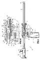
身体組織、例えば、腹壁を貫通するために、かつ貫通されている身体組織の同時的な前方視野を提供するために装置が提供される。図1に示される、好ましい実施形態において、装置は、栓塞子アセンブリ12、カニューレアセンブリ14、および内視鏡16等の撮像部材を有するトロカールアセンブリ10を含む。内視鏡16は、貫通されている身体組織の観察を提供するために、栓塞子アセンブリ12内に配置される。本明細書で使用されるような栓塞子アセンブリという用語は、トロカールアセンブリ10の組織貫通アセンブリを指す。
An apparatus is provided for penetrating body tissue, eg, the abdominal wall, and for providing a simultaneous forward view of the body tissue being penetrated. In the preferred embodiment shown in FIG. 1, the apparatus includes a
図1および2を参照すると、栓塞子アセンブリ12は、筐体18と、縦方向に延在する栓塞子スリーブ20とを含む。栓塞子筐体18は、バレル部分19と、ハンドグリップ21とを含む。栓塞子筐体18には、ブレード平行移動レバー160が回転可能に載置される。栓塞子スリーブ20の近位端は、栓塞子スリーブ20が栓塞子筐体18から外向きに延在するように、バレル部分19のチャネル22内に固定される。ハンドグリップ21は、手術部位の周囲において操作を容易にするように、臨床医による手による把持のために提供される。
With reference to FIGS. 1 and 2, obturator assembly 12 includes a
栓塞子スリーブ20は、栓塞子スリーブ20の近位端と遠位端との間に延在する、縦方向孔24を有する。縦方向孔24は、図1に示されるように、内視鏡16の内視鏡部分26を受容するように構成および寸法決定される。栓塞子アセンブリ12の筐体18は、溶接、接着剤、または同等物によって共に接合される、2つの半断面で構成される。板バネ103は、図2に示されるように、筐体18のバレル部分19の近位端においてチャネル105内に配置される。板バネ103は、内視鏡16の内視鏡部分26に係合して、栓塞子スリーブ20に対して縦方向に固定された関係で内視鏡を摩擦によって保持するように提供される。
The
図2および3を参照すると、画像送出部材28は、栓塞子スリーブ20の遠位端に固定され、栓塞子スリーブ20内へ画像を誘導することを可能にするために、および/または栓塞子スリーブ20から身体組織への照明光の通過を可能にするために提供される。画像送出部材28は、ポリスチレン、ポリメチルメタクリレート(PMMA)、ポリウレタン、透明エポキシおよび/またはガラス、または他の透明材料等の、種々の材料から加工される、透明な光学窓または光学レンズであってもよい。この好ましい実施形態に示される光学窓は半球形、すなわち、ドーム形であり、光学像がそれを通って栓塞子スリーブ20の縦方向孔24の中に入り、内視鏡16の遠位端に衝突することを可能にすることができる。
With reference to FIGS. 2 and 3, the
対物光学部材もまた、ドーム形部材である。しかしながら、この構成では、対物光学部材28のドーム形表面に衝突する光学像は、内視鏡16の遠位端に衝突するように、栓塞子スリーブ20の縦方向孔24の中へ方向付けられる。対物光学部材ならびに光学窓は、好ましくは、ほぼ完全な前方視野角を可能にするように構成される。
The objective optical member is also a dome-shaped member. However, in this configuration, the optical image impinging on the dome-shaped surface of the objective
図2を参照すると、栓塞子アセンブリ12は、作動アセンブリ36に動作可能に接続される切断ブレード34を含む。切断ブレード34は、好ましくは、ドーム形画像送出部材28の外面に一致することが可能であるワイヤ、バンド、または同等物である。切断ブレード34、またはその少なくとも一部分は、組織の貫通を補助するために尖状または鋸歯状34a(図3)であってもよい。切断ブレード34の尖状または鋸歯状部分は、切断ブレード34が経験する側方平行移動の量に対応するように変更されてもよい。切断ブレード34は、非配備位置にある時には、ドーム形画像送出部材28の弓状陥凹内に組み合わされる。切断ブレード34は、好ましくは、示されるように、画像送出部材の外面に対して中央にある。したがって、視覚化されると、切断ブレードは、中央を通る細い線として見え、すなわち、身体の視認を妨害しないように視野を二等分する。
With reference to FIG. 2, the obturator assembly 12 includes a cutting blade 34 operably connected to the
ここで図2、4、5、および6を参照すると、作動アセンブリ36は、筐体18内に含有され、以下でさらに詳細に記載される、非配備位置(図4)と配備位置(図6)との間で略縦方向に切断ブレード34を移動させるように提供される。図2に示されるように、作動アセンブリ36は、筐体18中のチャネル104内に摺動可能に配置され、非作動位置と作動位置との間で移動可能であるトリガ102を含む。バネ106は、図5Aに示されるように、通常はトリガを非作動位置に付勢するために、筐体18とトリガ102との間で固定される。整列指108および109は、トリガ102から筐体18内の対応するチャネル110および111の中へ延在する。整列指108および109は、筐体18のチャネル104内でトリガ102の整列を保持するように提供される。
Referring now to FIGS. 2, 4, 5, and 6, the actuating
ハンマーブレード駆動ラッチ112は、トリガ102に固定されるか、またはそこから一体化して延在し、柱114の形のラッチ解放部材を含む。柱114は、図5に示されるように、2つの筐体の半分の間に、かつ各筐体の半分の対応するチャネル116の中へ延在する。チャネル116は、以下でさらに詳細に説明されるように、ハンマーラッチ112がハンマーに係合できるようにする縦方向部分116aと、ハンマーラッチ112をハンマーから係脱させる傾斜部分116bとを含む。
The hammer
図2および5を再度参照すると、作動アセンブリ36はまた、ハンマー120、ブッシングアセンブリ122、および一対の駆動バネ124および126等の、ブレード駆動部材も含む。図5に示されるように、ハンマー、ブッシング、および駆動バネは、栓塞子スリーブ20と同軸的に整列している。駆動バネ124は、バネの一方の端が筐体に係合し、他方の端がハンマー120の近位端に係合するように、各筐体の半分のチャネル128内で栓塞子スリーブ20の周囲に配置される。駆動バネ124は、図5の矢印「A」で示されるように、通常は栓塞子アセンブリ12の遠位端に向かってハンマー120を付勢する。ブッシングアセンブリ122の近位端は、ハンマー120に隣接して配置され、ブッシングアセンブリ122の遠位端は、駆動バネ126の一方の端に係合する。駆動バネ126の他方の端は、示されるように、筐体18に係合する。筐体18内でブッシングアセンブリ122からチャネル125の中へ延在する指123は、ブッシングアセンブリ122の近位および遠位運動、したがって、ブレード34の近位および遠位運動を制限するように提供される。
Referring again to FIGS. 2 and 5, the
図2および7を参照すると、切断ブレード34は、栓塞子スリーブ20のスロット39および41に配置される。切断ブレード34の近位端は、内側で摺動し、ブッシングアセンブリ122に動作可能に接続するように構成される、そこから外向きに延在する指130を含む。切断ブレード34は、ブッシングアセンブリ122との解放可能な係合のために構成されてもよい。好ましくは、切断ブレード34は、手技の間に、あるいは尖状または鋸歯状部分が鈍くなると交換されてもよい。
With reference to FIGS. 2 and 7, the cutting blade 34 is disposed in slots 39 and 41 of the
切断ブレード34の近位および遠位前進のために構成されることに加えて、ブッシングアセンブリ122は、栓塞子20の遠位端の付近で切断ブレード34の側方平行移動を可能にするようにさらに構成される。ブッシングアセンブリ122は、第1および第2の筐体の半分122a、122bを備える。第1および第2の筐体の半分122a、122bは、それぞれ陥凹150a、150bを形成する、実質的に左右対称像である。陥凹150a、150bは、その中に配置される上部および底部ブレード台50a、50bを摺動可能に保持するように構成される。第2の筐体の半分122bは、上部および底部ブレード台50a、50bへのアクセスを可能にするように構成される、開口部122cを含む。
In addition to being configured for proximal and distal advancement of the cutting blade 34, the
ブレード台50a、50bは、第1および第2の対向端52a、52b、53a、53bをそれぞれ有する、左右対称像の半弓状部材である。第1の端52a、52bは、ブレード台50a、50bが栓塞子20の周囲で組み立てられると、互いに摺動可能に係合するように構成される。第1の端52a、52bは、舌または溝構造、または、上部ブレード台50aが底部ブレード台50bに対して縦方向に摺動できるようにするための何らかの他の好適な方法を含んでもよい。第1および第2の筐体の半分122a、122bは、上部および底部ブレード台50a、50bを保持するようにさらに構成されてもよい。第2の端53a、53bは、栓塞子20の周囲で組み立てられると離間関係にとどまる、歯状または歯車状部分を形成する(図7)。ブレード台50a、50bは、切断ブレード34の近位端130を受容する、スロット51a、51bをそれぞれ含む。
The blade bases 50a and 50b are semi-circular members having a symmetric image having first and second opposing ends 52a, 52b, 53a and 53b, respectively. The first ends 52a, 52b are configured to slidably engage each other when the blade mounts 50a, 50b are assembled around the
依然として図2および7を参照すると、組み立てられた構成では、ブレード台50a、50bは、栓塞子20の周囲およびブッシングアセンブリ122の陥凹150a、150b内に保持される、環状スリーブを形成する。スロット51a、51bは、ワイヤ切断ブレード34の近位端130を受容する。当初、ブレード台50a、50bは、互いに整列するように、陥凹150a、150b内に配置される(図7および9)。こうして、ワイヤ切断ブレード34の近位端130が整列し、ブレード34の等しい長さが栓塞子20の上下に配置される。シャフト62上に載置される歯車61は、栓塞子筐体18に形成される開口部165、およびブッシングアセンブリ122に形成される開口部122cを通って延在し、上部および底部ブレード台50a、50bの歯状端53a、53bにそれぞれ動作可能に係合する。歯車161は、栓塞子筐体18の外部の上に回転可能に載置される、ブレード平行移動レバーまたはノブ160(図1)に動作可能に接続される。
Still referring to FIGS. 2 and 7, in the assembled configuration, the blade mounts 50a, 50b form an annular sleeve that is retained around the
ここで図1および5A−5Bを参照すると、第1または時計回りの方向(矢印「a」)でのレバー160の回転は、歯車161を同じ第1の方向に回転させる。歯車161の回転は、それぞれ上部および底部ブレード台50a、50bの歯状端53a、53bとの係合およびそれらの運動を引き起こす。歯車161が第1の方向に回転するにつれて、上部ブレード台50aは、栓塞子20に沿って陥凹150a内で遠位に前進させられ、底部ブレード台50aは、栓塞子20に沿って陥凹150b内で反対または近位方向に前進させられる。ブレード台50a、50bが互いと反対に前進するにつれて、それに動作可能に接続される切断ブレード34は、栓塞子20の遠位端の周辺で側方に平行移動させられる(矢印「c」)。この栓塞子20の遠位端の周辺での切断ブレード34の側方平行移動は、組織の貫通を助長するための切断動作を生成する。
Referring now to FIGS. 1 and 5A-5B, rotation of lever 160 in the first or clockwise direction (arrow “a”) causes
ブッシングアセンブリ122に形成される陥凹150a、150bは、ブレード台50a、50bが所定の範囲を越えて前進することを防止するように構成される。ブッシングアセンブリ122およびブレード台50a、50bは、より多いまたは少ない量の切断ブレード34の側方平行移動を可能にするように構成される。代替実施形態では、ブッシングアセンブリ122は、初期位置から近位または遠位方向のいずれかに、上部および底部ブレード台50a、50bの前進を可能にするように構成されてもよい。陥凹150a、150b内でのブレード台50a、50bの完全な前進時に、レバー160は、第1または時計回りの方向でのさらなる回転を防止される。レバー160は、指標を含むか、またはブッシングアセンブリ122を伴うブレード台50a、50bの相対位置を示すように構成されてもよい。第2または半時計回りの方向(矢印「b」)でのレバー160の回転は、ブレード台50a、50bをそれらの初期整列位置に戻す(図7および9A−9B)。こうして、切断ブレード34は、再度、栓塞子20の遠位端の周辺で側方に平行移動させられるが、今回は、反対方向(矢印「d」)に切断動作を生成する。
The recesses 150a, 150b formed in the
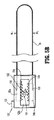
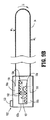
ここで図14Aおよび14Bを参照すると、栓塞子20の遠位端の周辺でブレード234の側方平行移動を提供するための機構の代替実施形態では、第1のブレード台250aは、ブッシングアセンブリ222内で強固に取り付けられ得る一方で、第2のブレード台250bは、上記の方式で側方に平行移動できるようになる。したがって、歯車261が回転して第2のブレード台250bの歯状端253bに係合するにつれて、第2のブレード台250bが側方に平行移動させられる一方で、第1のブレード台250aは、静止したままである(図14B)。ブレード234は、栓塞子20の遠位端の周辺で第1の方向にブレード234の側方平行移動を可能にするためのバネ部分234aを含むように構成される。一旦、歯車261を旋回させる力が除去されると、切断ブレード234のバネ部分234aは、ブレード334の側方後退を引き起こす。したがって、第2のブレード台250bは、初期位置に戻される(図14A)。
Referring now to FIGS. 14A and 14B, in an alternative embodiment of a mechanism for providing lateral translation of the
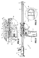
図8−13に戻って参照すると、上記の構成では、図8および9Aの矢印「B」によって示される、近位方向へのトリガ102の運動は、ハンマーラッチ112にハンマー120を後退させて、駆動バネ124を圧縮する(すなわち、ハンマーラッチがハンマーを、準備または装備位置に移動させる)。柱114は、チャネル116の縦方向部分116a内にあり、ブレード34は、図10に示されるように、対物光学部材28内の非配備(すなわち、後退)位置に残留し続ける。トリガ102のさらなる近位運動は、図11および12に示されるように、チャネル116の傾斜部分116b内で下向きの方向に柱114を移動させる。柱114の下方運動は、ハンマー120が駆動バネ124によって遠位に(すなわち、矢印「C」の方向に)突き出されるように、ハンマーラッチ112をハンマー120から係脱させる。ハンマー120が遠位に移動するにつれて、ハンマーは、ブッシングアセンブリ122に係合し、図11および13に示されるように、切断ブレード34を前進配備(すなわち、露出)位置へと縦方向に移動させるよう、ブッシングを遠位に突き出す。ブッシングアセンブリ122の遠位運動はまた、駆動バネ126を圧縮し、駆動バネ126の付勢力がハンマー120によって及ぼされる圧縮力を超える時に、駆動バネ126は、ブレード34が非配備位置に自動的に戻されるように、ブッシング124を近位に自動的に付勢する。したがって、ハンマー120およびブッシングアセンブリ122の係合は、ブレードの実質的に瞬時の配備および後退を提供するため、ブレードは、短期間に露出したままとなる。したがって、一旦、トリガが所定の位置へと引かれると、ブレード34が配備され、次いで、ユーザのさらなる作用無しで(すなわち、トリガのさらなる運動なしで)後退させられる。
Referring back to FIGS. 8-13, in the above configuration, the movement of the
筐体18は、レバー160およびそれを通って延在するシャフト62が、ブレード34の配備および後退中にブッシングアセンブリ122に対して移動することを可能にするように、開口部165を含む。したがって、切断ブレード34が配備および後退させられるにつれて、ブレード台50a、50bは、ブッシングアセンブリ122に対して、かつそれに沿って移動する。代替実施形態では、筐体18、より具体的には、開口部165、およびシャフト162、および/またはレバー60は、ブッシングアセンブリ122が配備または後退させられるにつれて、シャフト62、したがって歯車61が回転させられるように構成されてもよい。上記のように、歯車161の回転は、ブレード台50a、50bの前進を引き起こし、それにより、切断ブレード34の側方平行移動を引き起こす。こうして、切断ブレード34は、前後に縦方向に往復運動するとともに、栓塞子20の遠位端の周辺で側方に平行移動してもよい。レバー160およびシャフト162は、筐体18との選択的係合のためにさらに構成されてもよく、それにより、配備または後退位置のいずれかにある時に、栓塞子20の遠位端の周辺で切断ブレード34の選択的平行移動を可能にする。
The
説明された構成では、作動アセンブリ36は、二ステップ方式で動作する。第1のステップでは、トリガ102は、ハンマー120を引くように近位に移動させられる。第2のステップでは、トリガ102のさらなる近位運動は、ハンマー120を自動的に遠位に移動させて、ブレード34を配備位置に前進させ、ブレードは、駆動バネ126の力の下で非配備位置に自動的に戻される。この二ステップ方式は、トリガ102を完全に圧搾すると自動的に発生する。
In the described configuration, the
図1を再度参照すると、カニューレアセンブリ14は、カニューレ筐体52と、カニューレ筐体52に固定され、そこから外向きに延在するカニューレスリーブ54とを含む。栓塞子筐体18のバレル部分19は、カニューレ筐体52の近位端と相互嵌合するように構成および寸法決定されるブッシング56を含むため、栓塞子スリーブ20は、2つのアセンブリが相互嵌合されると、カニューレスリーブ54と同軸的に整列する。カニューレスリーブ54は、栓塞子アセンブリ12(および内視鏡16)の貫通およびその後の除去の後に体内に残留して、それを通る適切な内視鏡/腹腔鏡器具の挿入を可能にするように適合される。
Referring again to FIG. 1, the cannula assembly 14 includes a
カニューレ筐体内の気密性密封を維持するために、本発明の栓塞子アセンブリ12ならびに他の内視鏡手術器具を受容するように適合される、密封部材またはシステムがその内側に配置されてもよい。好適な密封システムの一例は、嘴状密封部材を利用する。例示的なカニューレアセンブリおよび密封システムのより詳細な説明は、参照することにより本明細書に組み込まれる、1993年1月19日発行の米国特許第5,180,373号に見出される。 A sealing member or system adapted to receive the obturator assembly 12 of the present invention as well as other endoscopic surgical instruments may be disposed therein to maintain an airtight seal within the cannula housing. . One example of a suitable sealing system utilizes a bowl-shaped sealing member. A more detailed description of an exemplary cannula assembly and sealing system is found in US Pat. No. 5,180,373 issued Jan. 19, 1993, which is incorporated herein by reference.
続けて図1を参照すると、内視鏡16は、内視鏡部分26と、内視鏡筐体58とを含む。内視鏡部分26は、内視鏡筐体58から内視鏡部分の遠位端へ照明光を転送して、手術部位に照明光を提供するように構成される。例示的構成では、内視鏡部分26は、外鞘60と、手術部位を照射するように内視鏡筐体58の光源コネクタ64と外鞘60の遠位端との間に延在する光ファイバ素子62の環状配列とを含む。任意の既知の光源が、照明光を提供するためにコネクタ64に接続されてもよい。
With continued reference to FIG. 1, the
内視鏡部分26は、内視鏡16の遠位端において受信される光学像を視認のための接眼レンズ68に転送する、CCD、光ファイバ素子の束、または対物レンズを含んでもよい画像転送システム66を含む。代替として、モニタを含むビデオシステムは、貫通されている身体組織のビデオ画像を提供するために、筐体58に動作可能に接続されてもよい。
The
好ましくは、光ファイバ素子62は、画像転送システムを包囲するように、外鞘の内壁に隣接して配置される。この構成では、内視鏡からの照明光は、画像送出部材28を通過させられ、画像送出部材28に衝突する光学像は、画像転送システム内を通過し、接眼レンズ68へと伝えられる。利用することができる内視鏡の一例は、参照することにより本明細書に組み込まれる、米国特許第4,964,710号で説明されている。
Preferably, the fiber optic element 62 is positioned adjacent to the inner wall of the outer sheath so as to surround the image transfer system. In this configuration, the illumination light from the endoscope is passed through the
代替実施形態では、栓塞子アセンブリ12および内視鏡16またはそれの光学構成要素は、カニューレアセンブリ14の中に挿入される単一ユニットであり得る。例えば、栓塞子アセンブリ自体が組織を貫通し、ならびに手術部位を照らしてビデオモニタに画像を伝送するように機能できるように、栓塞子アセンブリは、その中に配置される照明光学素子および/または撮像光学素子とともに製造することができる。この変形例では、栓塞子は、縦方向孔を持たず、それは密封される。
In an alternative embodiment, obturator assembly 12 and
作動中、内視鏡16は、図4に示されるように、トロカールアセンブリ10に、すなわち、栓塞子スリーブ20の縦方向孔24に挿入される。次いで、外科医は、身体組織に対してブレード34を配置し、トリガ102を連続的に圧搾して、ブレード34を迅速に非配備位置から配備位置へ、そして非配備位置に戻して自動的に移動させることによって、ブレード34を繰り返し移動させる。圧力は、身体組織を貫通するように遠位方向でハンドグリップ21に付与される。ブレード34の運動は、身体組織の制御された切断を促進し、外科医がハンドグリップ21に比較的最小の圧力を付与して身体組織を貫通できるようにする。同時に、外科医は、上記のように、第1および第2の方向にレバー160を手動で回転させることによって、栓塞子20の遠位端の周辺で切断ブレード34の側方平行移動を引き起こしてもよい。身体組織の貫通中、外科医は、接眼レンズ68を通してそのような貫通を観察するか、または、ビデオシステムが利用される場合は、外科医は、単純に任意の既知のビデオモニタを介して身体組織の貫通を観察するかのいずれかである。
In operation, the
代替として、外科医はまた、貫通中にブレード34をより選択的に配備してもよい。つまり、率直にいえば、外科医は、トロカールアセンブリを挿入して、筋肉等のより厚い組織に到達するまで身体組織を貫通してもよい。この時点で、この厚い組織を貫通する(突き刺す)ように、ブレードを配備および/または側方に平行移動させることができる。厚い組織に再度遭遇すると、ブレードを再度配備および/または側方に平行移動させることができる。体腔内への貫通後に、内視鏡16および栓塞子アセンブリ12の両方は、カニューレアセンブリ14から除去され、それを通る所望の器具の挿入のために、カニューレアセンブリ14を体内に残す。
Alternatively, the surgeon may also more selectively deploy the blade 34 during penetration. That is, frankly, a surgeon may insert a trocar assembly and penetrate body tissue until it reaches a thicker tissue such as a muscle. At this point, the blade can be deployed and / or translated laterally to penetrate (pierce) this thick tissue. When thick tissue is encountered again, the blade can be redeployed and / or translated laterally. After penetration into the body cavity, both the
その精神および範囲から逸脱することなく、種々の修正を本明細書で開示されている実施形態に行うことができると理解されるであろう。例えば、カニューレアセンブリ、栓塞子アセンブリの種々の直径、ならびに種々の直径の内視鏡が検討される。また、ブレードの瞬時の配備および後退を達成するように、種々の修正をトリガアセンブリの構成に行ってもよい。したがって、上記の説明は、限定的として解釈されるべきではないが、その好ましい実施形態の例示としてのみ解釈されたい。当業者であれば、本明細書に添付される請求項の範囲および精神内で他の修正を構想するであろう。 It will be understood that various modifications can be made to the embodiments disclosed herein without departing from its spirit and scope. For example, various diameters of cannula assemblies, obturator assemblies, as well as various diameter endoscopes are contemplated. Various modifications may also be made to the trigger assembly configuration to achieve instantaneous blade deployment and retraction. Therefore, the above description should not be construed as limiting, but merely as exemplifications of preferred embodiments thereof. Those skilled in the art will envision other modifications within the scope and spirit of the claims appended hereto.
Claims (17)
該外側部材の該遠位端に隣接して配置され、組織接触外面を有する先頭部材と、
該先頭部材に隣接して載置されるブレードであって、該ブレードは、少なくとも該縦方向軸に対する2つの方向における横断運動に適合され、それにより、該先頭部材の該外面を横断して、該組織内での該先頭部材の前進中に該組織の貫通を促進する、ブレードと
を備え、
該ブレードの該横断運動は、該2つの方向の各々において所定の範囲内に制限されるように構成されている、組織を貫通するための栓塞子。 An outer member defining a longitudinal axis and having a proximal end and a distal end;
A leading member disposed adjacent to the distal end of the outer member and having a tissue contacting outer surface;
A blade is mounted adjacent the top member, the blade is adapted to traverse movement in two directions to at least said longitudinal axis, whereby, across the outer surface of the distal head member, A blade that facilitates penetration of the tissue during advancement of the leading member within the tissue ; and
An obturator for penetrating tissue , wherein the transverse movement of the blade is configured to be limited within a predetermined range in each of the two directions .
該外側スリーブ部材の該遠位端に隣接して配置され、組織接触外面を有する光学部材であって、該内視鏡による検出のために物体の画像を転送するように適合される、光学部材と、
該光学部材に隣接して載置されるブレードであって、該ブレードは、少なくとも該縦方向軸に対する2つの方向における側方横断運動に適合され、それにより、先頭部材の外面を横断して、組織内での該光学部材の視覚化された前進中に該組織の貫通を促進する、ブレードと
を備え、
該ブレードの該側方横断運動は、該2つの方向の各々において所定の範囲内に制限されるように構成されている、光学栓塞子。 An outer sleeve member defining a longitudinal axis and having a proximal end and a distal end, the outer sleeve member including a longitudinal opening for receipt of an endoscope;
An optical member disposed adjacent to the distal end of the outer sleeve member and having a tissue contacting outer surface, the optical member adapted to transfer an image of an object for detection by the endoscope When,
A blade which is placed adjacent to the optical member, the blade is adapted to the side transverse movement in two directions to at least said longitudinal axis, whereby, across the outer surface of the first member, A blade that facilitates penetration of the tissue during the visual advancement of the optical member within the tissue ; and
An optical obturator configured to limit the lateral transverse movement of the blade within a predetermined range in each of the two directions .
A manual advancer operably connected to the blade, the manual advancer being manually operable to cause a corresponding movement of the blade between the initial position and the advanced position; The optical obturator according to claim 16 further comprising a manual advancer.
Applications Claiming Priority (3)
| Application Number | Priority Date | Filing Date | Title |
|---|---|---|---|
| US92284107P | 2007-04-11 | 2007-04-11 | |
| US60/922,841 | 2007-04-11 | ||
| PCT/US2008/059342 WO2008127887A1 (en) | 2007-04-11 | 2008-04-04 | Visualized entry trocar with moving blade |
Publications (2)
| Publication Number | Publication Date |
|---|---|
| JP2010523272A JP2010523272A (en) | 2010-07-15 |
| JP5437233B2 true JP5437233B2 (en) | 2014-03-12 |
Family
ID=39864298
Family Applications (1)
| Application Number | Title | Priority Date | Filing Date |
|---|---|---|---|
| JP2010503129A Expired - Fee Related JP5437233B2 (en) | 2007-04-11 | 2008-04-04 | Visualization entry trocar with moving blade |
Country Status (6)
| Country | Link |
|---|---|
| US (1) | US20100048994A1 (en) |
| EP (1) | EP2150186B1 (en) |
| JP (1) | JP5437233B2 (en) |
| AU (1) | AU2008239409B2 (en) |
| CA (1) | CA2681894A1 (en) |
| WO (1) | WO2008127887A1 (en) |
Families Citing this family (13)
| Publication number | Priority date | Publication date | Assignee | Title |
|---|---|---|---|---|
| USD629899S1 (en) * | 2009-05-18 | 2010-12-28 | Karl Storz Gmbh & Co. Kg | Medical instrument |
| US20120059247A1 (en) * | 2010-09-03 | 2012-03-08 | Speeg Trevor W V | Echogenic needle for biopsy device |
| USD652923S1 (en) * | 2010-10-01 | 2012-01-24 | Viking Systems, Inc. | Endoscope |
| NZ725053A (en) * | 2012-04-28 | 2018-05-25 | Physcient Inc | Methods and devices for soft tissue dissection |
| US9592069B2 (en) | 2012-04-28 | 2017-03-14 | Physcient, Inc. | Methods and devices for soft tissue dissection |
| JP6641289B2 (en) | 2014-04-18 | 2020-02-05 | ファイサイエント・インコーポレーテッド | Method and apparatus for soft tissue dissection |
| US10383651B2 (en) | 2014-04-22 | 2019-08-20 | Physcient, Inc. | Instruments, devices, and related methods for soft tissue dissection |
| US9835816B2 (en) * | 2015-06-10 | 2017-12-05 | Telect, Inc. | Fiber blocking kits |
| US11197687B2 (en) | 2018-08-01 | 2021-12-14 | Medtronic, Inc. | Medical tools for and methods of gaining access to extra vascular spaces |
| USD981563S1 (en) * | 2019-10-11 | 2023-03-21 | Aok Innovations, Llc | Chest tube insertion aid and handle assembly |
| US20220031390A1 (en) * | 2020-07-31 | 2022-02-03 | Medtronic, Inc. | Bipolar tool for separating tissue adhesions or tunneling |
| WO2022187871A1 (en) * | 2021-03-05 | 2022-09-09 | Rafael Holdings, Inc. | Videoscopic arthroscopic instruments, devices, and systems and methods of use and assembly |
| US11963692B2 (en) | 2021-04-30 | 2024-04-23 | Aok Innovations, Llc | Body cavity access device |
Family Cites Families (93)
| Publication number | Priority date | Publication date | Assignee | Title |
|---|---|---|---|---|
| US1727495A (en) * | 1929-09-10 | Beinhold h | ||
| US1380447A (en) * | 1919-06-14 | 1921-06-07 | Protein Products Corp | Trocar |
| US2764148A (en) * | 1950-07-11 | 1956-09-25 | Sheldon Edward Emannel | Endoscope means for the internal examination of the human body |
| US2699770A (en) * | 1951-05-11 | 1955-01-18 | Centre Nat Rech Scient | Endoscope |
| US2784149A (en) * | 1953-06-25 | 1957-03-05 | Purification of vinyl acetate | |
| US3021834A (en) * | 1954-03-11 | 1962-02-20 | Sheldon Edward Emanuel | Endoscopes |
| US2877368A (en) * | 1954-03-11 | 1959-03-10 | Sheldon Edward Emanuel | Device for conducting images |
| US3499107A (en) * | 1954-03-11 | 1970-03-03 | Sheldon Edward E | Light transfer devices using light conducting members of multilayered construction and photoelectric means |
| US3437747A (en) * | 1964-03-24 | 1969-04-08 | Sheldon Edward E | Devices for inspection using fiberoptic members |
| US3558085A (en) * | 1968-12-19 | 1971-01-26 | John W Magill | Airport surface layout |
| US3809095A (en) * | 1969-10-15 | 1974-05-07 | H Cimber | Aspirator needle injector |
| GB1356386A (en) * | 1970-06-03 | 1974-06-12 | Nat Res Dev | Artery entry tool |
| DE2157911C2 (en) * | 1970-12-11 | 1982-02-04 | Marc Edmond Jean van Bruxelles Hoorn | Surgical device for ligating internal structures |
| DK131542C (en) * | 1974-02-06 | 1976-02-09 | Akad Tekn Videnskaber | SURGICAL INSTRUMENT FOR SAMPLING BIOLOGICAL SAMPLES |
| US3915169A (en) * | 1974-11-14 | 1975-10-28 | George Mcguire | Surgical knife having malleable shank |
| US4269192A (en) * | 1977-12-02 | 1981-05-26 | Olympus Optical Co., Ltd. | Stabbing apparatus for diagnosis of living body |
| US4220155A (en) * | 1978-05-11 | 1980-09-02 | Colorado State University Research Foundation | Apparatus for spaying large animals |
| US4210146A (en) * | 1978-06-01 | 1980-07-01 | Anton Banko | Surgical instrument with flexible blade |
| GB2048686B (en) * | 1979-05-15 | 1983-03-16 | Wolf Gmbh Richard | Endoscopc instrumentation apparatus |
| US4256119A (en) * | 1979-09-17 | 1981-03-17 | Gauthier Industries, Inc. | Biopsy needle |
| US4254762A (en) * | 1979-10-23 | 1981-03-10 | Inbae Yoon | Safety endoscope system |
| US4461305A (en) * | 1981-09-04 | 1984-07-24 | Cibley Leonard J | Automated biopsy device |
| US4411653A (en) * | 1982-01-28 | 1983-10-25 | Razi M Dean | Cannula introducer |
| US4516575A (en) * | 1982-06-03 | 1985-05-14 | Coopervision, Inc. | Surgical scalpel |
| US4601710B1 (en) * | 1983-08-24 | 1998-05-05 | United States Surgical Corp | Trocar assembly |
| US4539976A (en) * | 1984-02-08 | 1985-09-10 | Sharpe Jewett M | Endoscopic surgical instrument |
| JPS60179057A (en) * | 1984-02-28 | 1985-09-12 | 雪印乳業株式会社 | Fertilized egg transplantation triple needle for laparoscope |
| US4570632A (en) * | 1984-03-16 | 1986-02-18 | Woods Randall L | Cystotome for eye surgery and method of opening lens capsule |
| US4667684A (en) * | 1985-02-08 | 1987-05-26 | Bio-Medical Resources, Inc. | Biopsy device |
| US4723545A (en) * | 1986-02-03 | 1988-02-09 | Graduate Hospital Foundation Research Corporation | Power assisted arthroscopic surgical device |
| US4865029A (en) * | 1986-04-24 | 1989-09-12 | Eye Research Institute Of Retina Foundation | Endophotocoagulation probe |
| US4991269A (en) * | 1987-03-13 | 1991-02-12 | Akitada Kuroda | Clip |
| US4733671A (en) * | 1987-03-17 | 1988-03-29 | Mehl Donald N | Tissue needle |
| US4962770A (en) * | 1987-09-18 | 1990-10-16 | John M. Agee | Surgical method |
| US5089000A (en) * | 1987-09-18 | 1992-02-18 | John M. Agee | Surgical method and instrument therefor |
| US4957112A (en) * | 1987-11-20 | 1990-09-18 | Olympus Optical Co., Ltd. | Ultrasonic diagnostic apparatus |
| US5146921A (en) * | 1987-11-27 | 1992-09-15 | Vance Products Inc. | Biopsy instrument stylet and cannula assembly |
| US4904246A (en) * | 1988-07-19 | 1990-02-27 | Snyder Laboratories, Inc. | Cannula assembly |
| US5092872A (en) * | 1989-07-28 | 1992-03-03 | Jacob Segalowitz | Valvulotome catheter |
| US5007481A (en) * | 1990-02-02 | 1991-04-16 | Exxon Chemical Patents, Inc. | Method of treating subterranean formations using a non-damaging fracturing fluid |
| US5116353B1 (en) * | 1990-10-05 | 1996-09-10 | Digital Voice Systems Inc | Safety trocar |
| DE4035146A1 (en) * | 1990-11-06 | 1992-05-07 | Riek Siegfried | INSTRUMENT FOR PENETRATING BODY TISSUE |
| US5250068A (en) * | 1990-11-30 | 1993-10-05 | Yakuouji Shinkiyu Chiryouin | Optical transmission type acupuncture needle |
| US5104382A (en) * | 1991-01-15 | 1992-04-14 | Ethicon, Inc. | Trocar |
| US5152754A (en) * | 1991-02-15 | 1992-10-06 | Minnesota Mining And Manufacturing Company | Trocar |
| US5183053A (en) * | 1991-04-12 | 1993-02-02 | Acuderm, Inc. | Elliptical biopsy punch |
| US5591186A (en) * | 1991-05-22 | 1997-01-07 | Wurster; Helmut | Self-cutting trocar |
| US5176695A (en) * | 1991-07-08 | 1993-01-05 | Davinci Medical, Inc. | Surgical cutting means |
| US5158552A (en) * | 1991-11-04 | 1992-10-27 | American Cyanamid Company | Safety trocar instrument having a retractable trocar actuated by relief of pressure on the trocar point |
| US5188176A (en) * | 1991-11-08 | 1993-02-23 | Atlantic Richfield Company | Cement slurries for diviated wells |
| US5290276A (en) * | 1992-02-06 | 1994-03-01 | Sewell Jr Frank | Rotatable laparoscopic puncturing instrument |
| DE4229310A1 (en) * | 1992-09-02 | 1994-03-10 | Winter & Ibe Olympus | Medical instrument for creating a tissue channel |
| US5275583A (en) * | 1992-10-05 | 1994-01-04 | Lawrence Crainich | Trocar assembly with independently acting shield means |
| US5354302A (en) * | 1992-11-06 | 1994-10-11 | Ko Sung Tao | Medical device and method for facilitating intra-tissue visual observation and manipulation of distensible tissues |
| US5562696A (en) * | 1992-11-12 | 1996-10-08 | Cordis Innovasive Systems, Inc. | Visualization trocar |
| US5385572A (en) * | 1992-11-12 | 1995-01-31 | Beowulf Holdings | Trocar for endoscopic surgery |
| US5334150A (en) * | 1992-11-17 | 1994-08-02 | Kaali Steven G | Visually directed trocar for laparoscopic surgical procedures and method of using same |
| US5314417A (en) * | 1992-12-22 | 1994-05-24 | Ethicon, Inc. | Safety trocar |
| US5731804A (en) * | 1995-01-18 | 1998-03-24 | Immersion Human Interface Corp. | Method and apparatus for providing high bandwidth, low noise mechanical I/O for computer systems |
| US5467762A (en) * | 1993-09-13 | 1995-11-21 | United States Surgical Corporation | Optical trocar |
| US5441041A (en) * | 1993-09-13 | 1995-08-15 | United States Surgical Corporation | Optical trocar |
| US5609562A (en) * | 1993-11-16 | 1997-03-11 | Worldwide Optical Trocar Licensing Corporation | Visually directed trocar and method |
| US5720761A (en) * | 1993-11-16 | 1998-02-24 | Worldwide Optical Trocar Licensing Corp. | Visually directed trocar and method |
| US5445142A (en) * | 1994-03-15 | 1995-08-29 | Ethicon Endo-Surgery, Inc. | Surgical trocars having optical tips defining one or more viewing ports |
| CA2149290C (en) * | 1994-05-26 | 2006-07-18 | Carl T. Urban | Optical trocar |
| US5658306A (en) * | 1994-07-01 | 1997-08-19 | Archimedes Surgical, Inc. | Method for making additional incisions in laparoscopic surgery |
| US5632717A (en) * | 1994-10-07 | 1997-05-27 | Yoon; Inbae | Penetrating endoscope |
| US5569291A (en) * | 1995-02-01 | 1996-10-29 | Ethicon Endo-Surgery, Inc. | Surgical penetration and dissection instrument |
| US5591192A (en) * | 1995-02-01 | 1997-01-07 | Ethicon Endo-Surgery, Inc. | Surgical penetration instrument including an imaging element |
| US5662673A (en) * | 1995-04-05 | 1997-09-02 | Kieturakis; Maciej J. | Surgical trocar and method for placing a trocar sleeve in a body wall |
| AU2665297A (en) * | 1996-04-10 | 1997-10-29 | Endoscopic Technologies, Inc. | Instruments for cardiovascular surgery |
| DE19626408A1 (en) * | 1996-07-01 | 1998-01-08 | Berchtold Gmbh & Co Geb | Trocar for laparoscopic operations |
| US6039748A (en) * | 1997-08-05 | 2000-03-21 | Femrx, Inc. | Disposable laparoscopic morcellator |
| US6447527B1 (en) * | 1998-04-23 | 2002-09-10 | Ronald J. Thompson | Apparatus and methods for the penetration of tissue |
| US6030402A (en) * | 1998-04-23 | 2000-02-29 | Thompson; Ronald J. | Apparatus and methods for the penetration of tissue, and the creation of an opening therein |
| US6056766A (en) * | 1998-06-09 | 2000-05-02 | Thompson; Ronald J. | Stabilized trocar, and method of using same |
| US6319266B1 (en) * | 2000-03-16 | 2001-11-20 | United States Surgical Corporation | Trocar system and method of use |
| ES2334841T3 (en) * | 2000-08-08 | 2010-03-16 | Tyco Healthcare Group Lp | MOLDED TROCAR LATCH. |
| US7544206B2 (en) * | 2001-06-29 | 2009-06-09 | Medtronic, Inc. | Method and apparatus for resecting and replacing an aortic valve |
| US6602267B2 (en) * | 2001-10-17 | 2003-08-05 | Medcanica, Inc. | Articulable and reciprocable surgical knife |
| US6916328B2 (en) * | 2001-11-15 | 2005-07-12 | Expanding Concepts, L.L.C | Percutaneous cellulite removal system |
| USD518177S1 (en) * | 2002-03-08 | 2006-03-28 | Erblan Surgical, Inc. | Safety trocar with progressive cutting tip guards and gas jet tissue deflector |
| US6939341B2 (en) * | 2002-06-28 | 2005-09-06 | Dutch Opthalmic Research Center (D.O.R.C.) | Surgical cutting tool |
| US7056329B2 (en) * | 2002-10-23 | 2006-06-06 | Intellimed Surgical Solutions, Llc | Laparoscopic direct vision dissecting port |
| US7041115B2 (en) * | 2002-11-18 | 2006-05-09 | A.M. Surgical, Inc. | Endoscopic surgical procedure |
| US7811293B2 (en) * | 2003-01-31 | 2010-10-12 | Philip J. Simpson | System and method for rapid placement of chest tubes |
| US7481817B2 (en) * | 2003-02-13 | 2009-01-27 | Lsi Soultions, Inc. | Instrument for surgically cutting tissue and method of use |
| USD517694S1 (en) * | 2003-08-12 | 2006-03-21 | Erblan Surgical, Inc | Tip portion of an infusor |
| EP2545863B1 (en) * | 2003-10-03 | 2020-06-17 | Applied Medical Resources Corporation | Bladeless optical obturator |
| US7329279B2 (en) * | 2003-12-23 | 2008-02-12 | Sadra Medical, Inc. | Methods and apparatus for endovascularly replacing a patient's heart valve |
| US7988670B2 (en) * | 2005-06-30 | 2011-08-02 | Tyco Healthcare Group Lp | Trocar assembly with rotatable obturator housing |
| US7524331B2 (en) * | 2006-04-06 | 2009-04-28 | Medtronic Vascular, Inc. | Catheter delivered valve having a barrier to provide an enhanced seal |
| EP1875874B1 (en) * | 2006-07-06 | 2013-02-27 | Covidien LP | Two mode trocar assembly |
-
2008
- 2008-04-04 CA CA002681894A patent/CA2681894A1/en not_active Abandoned
- 2008-04-04 JP JP2010503129A patent/JP5437233B2/en not_active Expired - Fee Related
- 2008-04-04 AU AU2008239409A patent/AU2008239409B2/en not_active Ceased
- 2008-04-04 EP EP08745070.6A patent/EP2150186B1/en not_active Not-in-force
- 2008-04-04 WO PCT/US2008/059342 patent/WO2008127887A1/en not_active Ceased
- 2008-04-04 US US12/594,609 patent/US20100048994A1/en not_active Abandoned
Also Published As
| Publication number | Publication date |
|---|---|
| EP2150186A4 (en) | 2013-06-12 |
| EP2150186B1 (en) | 2015-11-11 |
| AU2008239409A1 (en) | 2008-10-23 |
| AU2008239409B2 (en) | 2013-09-19 |
| US20100048994A1 (en) | 2010-02-25 |
| CA2681894A1 (en) | 2008-10-23 |
| JP2010523272A (en) | 2010-07-15 |
| WO2008127887A1 (en) | 2008-10-23 |
| EP2150186A1 (en) | 2010-02-10 |
Similar Documents
| Publication | Publication Date | Title |
|---|---|---|
| JP5437233B2 (en) | Visualization entry trocar with moving blade | |
| JP3672618B2 (en) | Optical trocar | |
| EP0642764B1 (en) | Optical Trocar | |
| JP5248596B2 (en) | Visualization obturator with handle | |
| US5441041A (en) | Optical trocar | |
| US6447527B1 (en) | Apparatus and methods for the penetration of tissue | |
| JP4968818B2 (en) | Optical trocar with observation instrument holding assembly | |
| CA2811730C (en) | Micro laparoscopy devices and deployments thereof | |
| JP2006280918A (en) | Optical closure | |
| Zheng et al. | Project Proposal Optical Access Trocar Obturator |
Legal Events
| Date | Code | Title | Description |
|---|---|---|---|
| A621 | Written request for application examination |
Free format text: JAPANESE INTERMEDIATE CODE: A621 Effective date: 20110307 |
|
| A521 | Request for written amendment filed |
Free format text: JAPANESE INTERMEDIATE CODE: A523 Effective date: 20120223 |
|
| A131 | Notification of reasons for refusal |
Free format text: JAPANESE INTERMEDIATE CODE: A131 Effective date: 20121115 |
|
| A977 | Report on retrieval |
Free format text: JAPANESE INTERMEDIATE CODE: A971007 Effective date: 20121115 |
|
| A02 | Decision of refusal |
Free format text: JAPANESE INTERMEDIATE CODE: A02 Effective date: 20130529 |
|
| A521 | Request for written amendment filed |
Free format text: JAPANESE INTERMEDIATE CODE: A523 Effective date: 20130926 |
|
| A911 | Transfer to examiner for re-examination before appeal (zenchi) |
Free format text: JAPANESE INTERMEDIATE CODE: A911 Effective date: 20131004 |
|
| TRDD | Decision of grant or rejection written | ||
| A01 | Written decision to grant a patent or to grant a registration (utility model) |
Free format text: JAPANESE INTERMEDIATE CODE: A01 Effective date: 20131205 |
|
| A61 | First payment of annual fees (during grant procedure) |
Free format text: JAPANESE INTERMEDIATE CODE: A61 Effective date: 20131211 |
|
| R150 | Certificate of patent or registration of utility model |
Free format text: JAPANESE INTERMEDIATE CODE: R150 |
|
| LAPS | Cancellation because of no payment of annual fees |