JP5437657B2 - Molding apparatus and molding method - Google Patents
Molding apparatus and molding method Download PDFInfo
- Publication number
- JP5437657B2 JP5437657B2 JP2009034249A JP2009034249A JP5437657B2 JP 5437657 B2 JP5437657 B2 JP 5437657B2 JP 2009034249 A JP2009034249 A JP 2009034249A JP 2009034249 A JP2009034249 A JP 2009034249A JP 5437657 B2 JP5437657 B2 JP 5437657B2
- Authority
- JP
- Japan
- Prior art keywords
- mold
- molding
- cushion layer
- skin layer
- base material
- Prior art date
- Legal status (The legal status is an assumption and is not a legal conclusion. Google has not performed a legal analysis and makes no representation as to the accuracy of the status listed.)
- Expired - Fee Related
Links
Images




Landscapes
- Injection Moulding Of Plastics Or The Like (AREA)
- Moulds For Moulding Plastics Or The Like (AREA)
- Casting Or Compression Moulding Of Plastics Or The Like (AREA)
Description
本発明は、基材と該基材の表面側に設けられる表皮層との間にクッション層を有する樹脂製品を成形する際に用いられる成形装置及び成形方法に関する。 The present invention relates to a molding apparatus and a molding method used when molding a resin product having a cushion layer between a base material and a skin layer provided on the surface side of the base material.
従来より、例えば、車両用内装材として、基材と該基材の表面側を覆うように設けられる表皮層との間にクッション層を有する樹脂製品が用いられている(例えば、特許文献1、2参照)。特許文献1、2の樹脂製品のクッション層は、成形型を閉じた状態でキャビティに原料を注入して反応硬化させることによって成形する、いわゆる反応射出成形法(Reaction Injection Molding)によって成形されている。この反応射出成形法では、キャビティに注入された原料は、自己の発泡作用によってキャビティ内を流動していくことになる。
ところで、例えば樹脂製品が縦壁を有するような形状で、かつ、クッション層が数ミリ厚程度で薄い場合がある。そのような場合では、キャビティが部分的に狭い形状となっているので、反応射出成形法でキャビティに注入した原料は自己の発泡作用によってのみではキャビティの隅々に行き渡り難い。クッション層の原料がキャビティ全体に行き渡っていないと、完成した樹脂製品の部位によって手で触れたときの硬さが異なり、触感の悪化を招いたり、樹脂製品の表面に窪み等が現れて成形不良を招く原因となる。 By the way, for example, a resin product may have a vertical wall and the cushion layer may be as thin as several millimeters. In such a case, since the cavity is partially narrow, the raw material injected into the cavity by the reaction injection molding method cannot easily reach every corner of the cavity only by its own foaming action. If the cushion layer material does not reach the entire cavity, the hardness when touched by the hand varies depending on the part of the finished resin product, resulting in deterioration of the touch feeling, or depressions etc. appearing on the surface of the resin product. Cause inconvenience.
本発明は斯かる点に鑑みてなされたものであり、その目的とするところは、樹脂製品が縦壁を有し、かつ、クッション層が薄い場合であっても、クッション層を狙い通りに成形できるようにして樹脂製品の触感を良好にするとともに、成形不良の発生を抑制することにある。 The present invention has been made in view of such points, and the object is to form the cushion layer as intended even if the resin product has a vertical wall and the cushion layer is thin. This makes it possible to improve the feel of the resin product and to suppress the occurrence of molding defects.
上記目的を達成するために、本発明では、成形型を開いた状態でクッション層の原料をキャビティの容積に相当する量だけ供給してから、成形型を閉じることにより、成形型による押圧力を利用してクッション層の原料を流動させるようにした。 In order to achieve the above object, in the present invention, with the mold opened, the cushion layer raw material is supplied in an amount corresponding to the volume of the cavity, and then the mold is closed to reduce the pressing force by the mold. The material of the cushion layer was used to flow.
具体的には、第1の発明では、基材と該基材の表面側に設けられる表皮層との間にクッション層を有する樹脂製品の成形装置であって、樹脂製品の表皮層側に対応するように配置される凹型成形面を有する第1成形型と、樹脂製品の基材側に対応するように配置され、上記凹型成形面内に入る凸型成形面を有する第2成形型と、上記第1成形型及び上記第2成形型を型閉じ状態と型開き状態とに切り替える型駆動装置と、クッション層となる発泡原料を、上記凹型成形面及び上記凸型成形面により形成されるキャビティの容積に相当する量だけ供給するためのクッション層原料供給装置とを備え、上記型駆動装置によって上記第1成形型及び上記第2成形型を型開き状態とし、上記第1成形型に保持されている表皮層となる部材と、上記第2成形型に保持されている基材との間に上記クッション層原料供給装置により上記発泡原料を供給させてから、上記型駆動装置によって上記第1成形型及び上記第2成形型を型閉じ状態に切り替えながら、上記発泡原料を発泡前に上記基材によりキャビティ内で押し拡げるように構成されているものとする。 Specifically, in the first invention, a molding apparatus for a resin product having a cushion layer between a base material and a skin layer provided on the surface side of the base material, corresponding to the skin layer side of the resin product A first molding die having a concave molding surface arranged so as to perform, a second molding die arranged to correspond to the base side of the resin product and having a convex molding surface that falls within the concave molding surface; A mold drive device that switches the first mold and the second mold between a mold closed state and a mold open state, and a foaming raw material that becomes a cushion layer is formed by a cavity formed by the concave mold surface and the convex mold surface. And a cushion layer raw material supply device for supplying an amount corresponding to the volume of the first mold and the second mold are opened by the mold driving device and held in the first mold. A member to be a skin layer, and the second It was allowed to supply the foaming material by the cushion layer material supply device between the substrate held in the form type, the mold closing state the first mold and the second mold by the mold driving device It is assumed that, while switching, the foaming raw material is expanded in the cavity by the base material before foaming .
この構成によれば、凹型成形面と凸型成形面とにより、縦壁を有する樹脂製品が成形される。成形工程においては、表皮層となる部材と基材との間に、クッション層原料供給装置によりキャビティの容積に相当する量のクッション層の原料が供給される。そして、型駆動装置によって第1成形型と第2成形型とを閉じる際、両成形型が接近していくと、クッション層の原料が基材によりキャビティ内で押し拡げられる。これにより、クッション層の原料は、反応射出成形法のように自己の発泡作用によることなく、成形型の押圧力によって強制的に流動するので、キャビティの隅々まで行き渡るようになる。 According to this configuration, a resin product having a vertical wall is formed by the concave molding surface and the convex molding surface. In the molding step, the cushion layer raw material in an amount corresponding to the volume of the cavity is supplied between the member to be the skin layer and the base material by the cushion layer raw material supply device. When the first mold and the second mold are closed by the mold driving device, the raw materials of the cushion layer are expanded in the cavity by the base material when both molds approach each other. As a result, the material of the cushion layer is forced to flow by the pressing force of the molding die without using its own foaming action as in the case of the reaction injection molding method, so that the cushion layer material reaches every corner of the cavity.
第2の発明では、第1の発明において、表皮層の原料を第1成形型の成形面に供給するための表皮層原料供給装置を備えている構成とする。 According to a second invention, in the first invention, a skin layer material supply device is provided for supplying the skin layer material to the molding surface of the first mold.
この構成によれば、表皮層原料供給装置により表皮層の原料を第1成形面に供給することで、表皮層となる部材を第1成形型の成形面で成形した後、脱型することなく、クッション層を成形して基材と一体の樹脂製品を得ることが可能になる。 According to this configuration, the material for the skin layer is supplied to the first molding surface by the skin layer material supply device, so that the member to be the skin layer is molded on the molding surface of the first molding die, and then is not demolded. The cushion layer can be molded to obtain a resin product that is integral with the base material.
第3の発明では、第1または2の発明において、基材のクッション層側に、該クッション層との接着性を向上させるプライマーを塗布するためのプライマー供給装置を備えている構成とする。 According to a third invention, in the first or second invention, a primer supply device for applying a primer for improving adhesion to the cushion layer is provided on the cushion layer side of the base material.
この構成によれば、第2成形型に保持された基材がプライマーを介してクッション層と強固に接着するようになる。 According to this structure, the base material hold | maintained at the 2nd shaping | molding die comes to adhere | attach firmly with a cushion layer via a primer.
第4の発明では、基材と該基材の表面側に設けられる表皮層との間にクッション層を有する樹脂製品の成形方法であって、樹脂製品の表皮層側に対応するように配置される凹型成形面を有する第1成形型に表皮層となる部材を保持させた状態とする工程と、樹脂製品の基材側に対応するように配置され、上記凹型成形面内に入る凸型成形面を有する第2成形型に基材を保持させた状態とする工程と、上記第1成形型に保持されている表皮層となる部材と、上記第2成形型に保持されている基材との間に、該第1成形型及び該第2成形型を開いた状態でクッション層となる発泡原料をキャビティの容積に相当する量だけ供給する工程と、上記クッション層となる発泡原料を供給した後に、上記第1成形型と上記第2成形型とを閉じながら、上記発泡原料を発泡前に上記基材によりキャビティ内で押し拡げる工程とを備えている構成とする。 According to a fourth aspect of the present invention, there is provided a molding method for a resin product having a cushion layer between a base material and a skin layer provided on the surface side of the base material, and the resin product is disposed so as to correspond to the skin layer side of the resin product. A first mold having a concave mold surface and a step of holding a member to be a skin layer, and a convex mold that is disposed so as to correspond to the substrate side of the resin product and enters the concave mold surface A step of holding a substrate in a second mold having a surface, a member to be a skin layer held by the first mold, and a substrate held by the second mold Between the step of supplying the foaming raw material to be the cushion layer with the first molding die and the second molding die being opened in an amount corresponding to the volume of the cavity, and supplying the foaming raw material to be the cushion layer later, while closing the said first mold and said second mold, the By the base foam material before foaming a configuration that a step of spreading pressed in the cavity.
この構成によれば、第1の発明と同様に、クッション層の原料が強制的に流動することになり、キャビティの隅々まで行き渡るようになる。 According to this configuration, as in the first invention, the raw material of the cushion layer is forced to flow and reaches every corner of the cavity.
第1の発明によれば、表皮層となる部材と基材との間にクッション層の原料をキャビティの容積に相当する量だけ供給した後に、第1成形型と第2成形型とを型閉じ状態に切り替え、このとき、基材によりクッション層の原料を押し拡げることができるので、クッション層の原料を強制的に流動させてキャビティの隅々に行き渡らせることができる。これにより、樹脂製品が縦壁を有し、かつ、クッション層が薄い場合であっても、クッション層を狙い通りに成形できるので、触感を良好にできるとともに、成形不良の発生を抑制できる。 According to the first aspect of the present invention, after the cushion layer raw material is supplied between the member to be the skin layer and the base material in an amount corresponding to the volume of the cavity, the first mold and the second mold are closed. At this time, since the raw material of the cushion layer can be pushed and expanded by the base material, the raw material of the cushion layer can be forced to flow and spread throughout the cavity. Thereby, even if the resin product has a vertical wall and the cushion layer is thin, the cushion layer can be molded as intended, so that the tactile sensation can be improved and the occurrence of molding defects can be suppressed.
第2の発明によれば、第1成形型の成形面で成形した表皮層となる部材を脱型することなく、第1成形型に保持したまま、樹脂製品を得ることができる。従って、表皮層の表面にシボ等の模様を設ける場合に、脱型して他の型に保持させることに起因する模様の潰れ等を回避することができ、鮮明な模様を得ることができる。 According to the second invention, a resin product can be obtained while being held in the first mold without removing the member to be the skin layer molded on the molding surface of the first mold. Therefore, when a pattern such as a grain is provided on the surface of the skin layer, it is possible to avoid a pattern collapse caused by demolding and holding it in another mold, and a clear pattern can be obtained.
第3の発明によれば、基材のクッション層側にクッション層との接着性を向上させるプライマーを塗布するようにしたので、クッション層の成形の際に、同時に、該クッション層と基材とを強固に接着できる。 According to the third invention, since the primer for improving the adhesion with the cushion layer is applied to the cushion layer side of the base material, the cushion layer and the base material are simultaneously formed when the cushion layer is formed. Can be firmly bonded.
第4の発明によれば、第1の発明と同様に、樹脂製品が縦壁を有し、かつ、クッション層が薄い場合であっても、クッション層を狙い通りに成形でき、触感を良好にできるとともに、成形不良の発生を抑制できる。 According to the fourth invention, similar to the first invention, even when the resin product has a vertical wall and the cushion layer is thin, the cushion layer can be molded as intended, and the tactile sensation is improved. And the occurrence of molding defects can be suppressed.
以下、本発明の実施形態を図面に基づいて詳細に説明する。尚、以下の好ましい実施形態の説明は、本質的に例示に過ぎず、本発明、その適用物或いはその用途を制限することを意図するものではない。 Hereinafter, embodiments of the present invention will be described in detail with reference to the drawings. It should be noted that the following description of the preferred embodiment is merely illustrative in nature, and is not intended to limit the present invention, its application, or its use.
図1は、本発明の実施形態に係る成形装置1を示すものである。成形装置1は、自動車の内装材(樹脂製品)100(図7に示す)を成形するためのものである。この内装材100は、図8に示すように、基材101と、基材101の表面側に設けられる表皮層102と、基材101及び表皮層102の間に設けられたクッション層103とを備えている。図8における符号104は、プライマーである。また、図7に示すように、内装材100は、本体板部100aと、本体板部100aの周縁部から本体板部100aの厚み方向に突出する縦板部(縦壁に相当)100bとを備えており、これら本体板部100aと縦板部100bとは一体成形されている。縦板部100bのクッション層103の厚さは、例えば3mm以下である。尚、内装材100としては、例えば、ドアトリム、インストルメントパネル、アームレスト等が挙げられるが、本実施形態の成形装置1は、乗員の手が触れる部分に用いられる内装材100を成形するのに特に適している。
FIG. 1 shows a
基材101は、ポリプロピレンが原料とされており、また、表皮層102は、ウレタン系の塗料が原料とされており、また、クッション層103はウレタンが原料とされている。
The
図1に示すように、成形装置1は、固定型(第1成形型)10及び可動型(第2成形型)11と、可動型11を駆動する型駆動装置12と、離型剤を供給する離型剤供給装置20と、クッション層103の原料を供給するクッション層原料供給装置30と、表皮層102の原料を供給する表皮層原料供給装置40と、プライマー104を供給するプライマー供給装置50と、制御装置60とを備えている。
As shown in FIG. 1, the
図2に示すように、固定型10の上面には、上方に開放し、内装材100の表皮層102の形状に略一致した凹面からなる凹型成形面10aが形成されている。凹型成形面10aには、表皮層102の表面にシボ模様を形成するための微小な凹凸形状が設けられている。固定型10の凹型成形面10aによって内装材100の表皮層102となる部材A(図4に示す)が成形され、成形された表皮層102となる部材Aは脱型されることなくそのまま凹型成形面10aに保持されるようになっている。
As shown in FIG. 2, the upper surface of the fixed
図5に示すように、可動型11は、固定型10の上方に配置されている。可動型11の下面には、内装材100の基材101の形状に略一致した凸型成形面11aが、型閉じ状態とされたときに凹型成形面10aに入るように形成されている。可動型11の凸型成形面11aに基材101が保持されるようになっている。凹型成形面10aと凸型成形面11aとにより、図7に示すように内装材100がその周縁部に縦壁を有する形状となる。
As shown in FIG. 5, the
型駆動装置12は、周知の油圧シリンダ等で構成されており、可動型11の上端部に連結されている。この型駆動装置12により、可動型11を上下方向、即ち固定型10に接離する方向に移動させることができるようになっている。
The
クッション層原料供給装置30は、図4に示すように、クッション層103の原料を貯留するタンク(図示せず)に接続された供給管31と、供給管31先端部に取り付けられたスプレーノズル32と、スプレーノズル32を動かすロボットアーム(図示せず)とを備えており、タンク内の原料を供給管31を流通させてスプレーノズル32から吐出させ、そのスプレーノズル32をロボットアームで動かすことによって固定型10の任意の部位に、任意の量の原料を供給することができるようになっている。スプレーノズル32及びロボットアームは制御装置60に接続され、該制御装置60により制御されるようになっている。
As shown in FIG. 4, the cushion layer raw
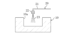
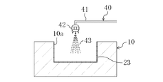
表皮層原料供給装置40は、図3に示すように、クッション層原料供給装置30と同様に、供給管41とスプレーノズル42とロボットアーム(図示せず)とを備えており、スプレーノズル42及びロボットアームが制御装置60により制御されるようになっている。また、図2に示すように、剥離剤供給装置20も供給管21とスプレーノズル22とロボットアーム(図示せず)とを備えており、スプレーノズル22及びロボットアームが制御装置60により制御されるようになっている。
As shown in FIG. 3, the skin layer raw
また、図6に示すように、プライマー供給装置50も、供給管51とスプレーノズル52とロボットアーム(図示せず)とを備えており、スプレーノズル52及びロボットアームが制御装置60により制御されるようになっている。
As shown in FIG. 6, the
制御装置60は、図1に示すように、型駆動装置12、離型剤供給装置20、クッション層原料供給装置30、表皮層原料供給装置40、プライマー供給装置50を制御するように構成されている。
As shown in FIG. 1, the
次に、上記のように構成された成形装置1を用いて内装材100を成形する要領について説明する。
Next, the point which shape | molds the
まず、型駆動装置12により、可動型11を固定型10から上方へ離して両型10,11を型開き状態とする(図1参照)。そして、剥離剤供給装置20により固定型10の凹型成形面10aに剥離剤23を塗布する。これが剥離剤塗布工程である。剥離剤23は、例えば一般的にウレタン表皮の成形時に使用されている剥離剤であればよく、ポリエチレンワックス系、α−メチルスチレン変性ジメチルポリシロキサン系等が挙げられる。また、剥離剤23を塗布する際の凹型成形面10aの温度は、例えば、50℃以上85℃以下の範囲で設定するのが好ましい。
First, the
剥離剤塗布工程の後、固定型10の凹型成形面10aにより表皮層102となる部材Aを成形する。すなわち、図3に示すように、表皮層原料供給装置40により、剥離剤23が付着した凹型成形面10aに表皮層102の原料となるウレタン系塗料43を塗布する。塗料43は、ポリウレタンを有機溶剤に溶解させた溶剤系塗料、ポリウレタンを水に分散させた水系塗料等が挙げられる。また、ウレタン系塗料43を塗布する際の凹型成形面10aの温度は、例えば、50℃以上85℃以下の範囲で設定するのが好ましい。
After the release agent coating step, the member A to be the
凹型成形面10aに塗布されたウレタン系塗料43が固化することで、図4に示すように、表皮層102となる部材Aが得られる。この表皮層102のなる部材Aの表面には、凹型成形面10aによりシボ模様が形成されている。表皮層102となる部材Aは、脱型することなく、凹型成形面10aに保持させておく。これが、固定型10に表皮層102を保持させた状態とする工程である。
As the urethane-based
次いで、同図に示すように、クッション層原料供給装置30によりクッション層103の原料となる発泡性ウレタン材料混合液33を表皮層102となる部材Aの裏面側に供給する。発泡性ウレタン材料混合液33は、供給直前に原料を混合させることによって得る。混合のタイミングは、スプレーノズル32から噴射する際にちょうど噴射可能な状態となるように調整する。
Next, as shown in the drawing, the foamable urethane material mixed
ウレタン材料混合液33の1回当たりの供給量は、凹型成形面10aと凸型成形面11aとで形成されるキャビティの容積に相当する量であり、この実施形態では、発泡による体積の増加を考慮した量となっている。ウレタン材料混合液33は、表皮層102となる部材Aの裏面に盛っておけばよい。ウレタン材料混合液33は、微発泡となるように調整されている。微発泡とは、発泡後の体積が発泡前の体積の2倍以下となる発泡度合いをいう。ウレタン材料混合液33の発泡度合いは発泡剤の添加量等によって任意に調整可能であり、発泡倍率を2倍より大きくしてもよい。
The supply amount of the urethane material mixed liquid 33 per one time is an amount corresponding to the volume of the cavity formed by the
ここで、ウレタン材料混合液33に含まれるポリオールとしては、ポリエーテルポリオール及びポリエステルポリオールが挙げられる。
Here, examples of the polyol contained in the urethane material mixed
ポリエーテルポリオールとしては、例えば、ポリプロピレングリコール系ポリオール、或いはそのエチレンオキサイド変性物やアミン変性物、ポリオキシテトラメチレングリコールなどのポリエーテルポリオール等が挙げられる。 Examples of the polyether polyol include polypropylene glycol-based polyol, or an ethylene oxide-modified product, an amine-modified product, and a polyether polyol such as polyoxytetramethylene glycol.
ポリエステルポリオールとしては、例えば、アジピン酸、イソフタル酸、テレフタル酸などのジカルボン酸とエチレングリコール、プロピレングリコール、ジエチレングリコール、ブチレングリコール、1,6−ヘキサンジオール、トリメチロールプロパン、ネオペンチルグリコールなどのポリオールとの縮合反応生成物、ポリカプロラクトンポリオール、ポリカーボネートポリオール等が挙げられる。 Examples of the polyester polyol include dicarboxylic acids such as adipic acid, isophthalic acid, and terephthalic acid, and polyols such as ethylene glycol, propylene glycol, diethylene glycol, butylene glycol, 1,6-hexanediol, trimethylolpropane, and neopentyl glycol. Examples include condensation reaction products, polycaprolactone polyols, and polycarbonate polyols.
ポリオールは、これらのうち単一種で構成されていても、複数種が混合されて構成されていてもどちらでもよい。 Of these, the polyol may be composed of a single species or a mixture of a plurality of species.
ウレタン材料混合液33に含まれるイソシアネートとしては、、例えば、1,4−テトラメチレンジイソシアネート、1,6ヘキサメチレンジイソシアネート、リジンジイソシアネートなど脂肪族系ジイソシアネート、イソホロンジイソシアネート、水添キシリレンジイソシアネート、水添4,4´−ジフェニルメタンジイソシアネートなどの脂環状系ジイソシアネート、キシレンジイソシアネート、トリレンジイソシアネート、4,4´−ジフェニルメタンジイソシアネート、トリジンジイソシアネート、p−フェニレンジイソシアネート、1,5−ナフチレンジイソシアネートなどの芳香族系ジイソシアネート等が挙げられる。イソシアネートは、これらのうち単一種で構成されていても、複数種が混合されて構成されていてもどちらでもよい。
Examples of the isocyanate contained in the urethane material mixed
一方、図9及び図10に示すように、基材101を別の成形装置70によって成形する。この成形装置70の構造について説明すると、成形装置70は、射出成形機(図示せず)と、固定型71及び可動型72とを備えている。射出成形機は従来周知のものなので詳細な説明は省略する。固定型71の上面には、基材101の裏面側を成形する成形面71aが形成されている。固定型71には、射出成形機のノズルに連通して成形面71aに開口するランナー71bが設けられている。可動型72の下面には、基材101の表面側を成形する成形面72aが形成されている。基材101は、固定型71と可動型72とを閉じた状態で射出成形機からポリプロピレンを射出してキャビティに充填させることにより得られる。この基材101を、図5に示すように、上記可動型11に保持させる。これが、可動型11に基材101を保持させた状態とする工程である。
On the other hand, as shown in FIGS. 9 and 10, the
可動型11に基材101を保持させた後、図6に示すように、プライマー供給装置50により、基材101の裏面側にプライマー104を塗布する。プライマー104は、ポリプロピレンとウレタンとの接着性を高めるものであり、例えば、変性ポリオレフィンを溶剤に溶解させたもので構成されている。
After the
変性ポリオレフィンは、ポリエチレンやポリプロピレンなどのポリオレフィンに官能基をグラフトしたものであって、例えば、アクリル酸変性ポリエチレン、アクリル酸変性ポリプロピレン、無水マレイン酸変性ポリエチレン、無水マレイン酸変性ポリプロピレンなどの酸変性ポリオレフィンが挙げられる。これらのうち、次工程において、基材101の主成分のポリプロピレンとの高い密着性を得ることができるという観点から、基材101の主成分のポリプロピレンと同種のポリ酸変性ポリプロピレンが好ましい。また、溶剤としては、例えば、ケトン系、アルコール系、グリコール系等が挙げられる。
The modified polyolefin is obtained by grafting a functional group to a polyolefin such as polyethylene or polypropylene. For example, an acid-modified polyolefin such as acrylic acid-modified polyethylene, acrylic acid-modified polypropylene, maleic anhydride-modified polyethylene, or maleic anhydride-modified polypropylene is used. Can be mentioned. Among these, in the next step, from the viewpoint that high adhesion to the main component polypropylene of the
プライマー104の塗布条件については、例えば、可動型11の温度を50〜85℃とするのが好ましい。
As for the application condition of the
尚、基材101を可動型11に保持させた後に、クッション層原料供給装置30によりウレタン材料混合液33を供給するのが好ましいが、逆の順序であっても構わない。
Although it is preferable to supply the urethane material mixed
しかる後、固定型10及び可動型11を型閉じ状態に切り替える。すなわち、型駆動装置12により可動型11を下方へ移動させて固定型10に接近させていく。すると、基材101の表面側がウレタン材料混合液33に押し付けられてウレタン材料混合液33はキャビティ内で押し拡げられ、可動型11の押圧力によって強制的に流動する。このとき、ウレタン材料混合液33が、反応射出成形法のように自己の発泡作用によることなく、固定型10及び可動型11に押圧されて流動しているので、図7に示すように、キャビティの隅々に行き渡る。さらに、ウレタン材料混合液33は発泡するものなので、非発泡原料に比べて流動性が高く、このことによっても、キャビティの隅々に行き渡り易くなる。
Thereafter, the fixed
このウレタン材料混合液33が発泡硬化するとクッション層103となる。プライマー104に含まれる変性ポリオレフィン樹脂の変性部分の極性基が表皮層102に対して分子間力を及ぼしたり、或いは、化学結合を形成することによるアンカー効果により、プライマー104が表皮層102に強固に密着する。一方、プライマー104に含まれる変性ポリオレフィン樹脂が基材101を形成する樹脂材料と密着する。これらにより、表皮層102がプライマー104を介して、ポリプロピレンを主成分とする樹脂材料で形成された基材101に強固に密着して一体化する。
When the urethane material mixed
そして、固定型10及び可動型11を開いて内装材100を取り出す。
Then, the fixed
以上のように、この実施形態によれば、固定型10の表皮層102となる部材Aと、可動型11の基材101との間にクッション層103の原料を供給した後に、型駆動装置12によって固定型10と可動型11とを接近させ、基材101によりクッション層103の原料を押し拡げるようにしたので、クッション層103の原料を強制的に流動させてキャビティの隅々に行き渡らせることができる。これにより、クッション層103が薄く、内装材100が縦壁を有する形状であっても、クッション層103を狙い通りに成形できるので、触感を良好にできるとともに、成形不良の発生を抑制できる。
As described above, according to this embodiment, after supplying the raw material of the
また、固定型10の凹型成形面10aで成形した表皮層102となる部材Aを脱型することなく、固定型10に保持したまま、内装材100を得ることができる。従って、表皮層102となる部材Aを、一旦脱型して他の型に保持させた場合のようにシボ模様が潰れる虞れはなく、鮮明なシボ模様を得ることができる。
In addition, the
また、クッション層103を発泡倍率が2倍以下の微発泡状態としたので、クッション感を与えながら、耐傷付き性を十分に確保することができる。
Further, since the
また、ウレタン材料混合液33を可動型11の移動によって流動させるようにしたので、ウレタン材料混合液33は表皮層102となる部材Aの裏面に盛るだけで済み、まんべんなく吹き付ける必要がない。従って、クッション層供給装置30のスプレーノズルとして安価なノズルを用いることができるとともに、ロボットアームの制御も簡単することができ、よって、成形装置1のコストを低減できる。スプレーノズル32を省略してもよく、これにより、より一層コストを低減できる。
In addition, since the urethane material mixed
また、ウレタン材料混合液33をキャビティに射出するようにした場合には、その射出圧が、表皮層102となる部材Aの一部に集中的に作用して損傷を与えることがあるが、本実施形態のように、ウレタン材料混合液33を可動型11の移動によって流動させるようにしたことで、表皮層102となる部材Aに作用するウレタン材料混合液33の圧力を低くでき、これにより、表皮層102となる部材Aの損傷を抑制できるとともに、該部材Aのずれも抑制できる。
In addition, when the urethane material mixed
また、表皮層102となる部材Aは、別の成形装置で成形した後に、固定型10の凹型成形面10aに保持させるようにしてもよい。
Further, the member A to be the
また、上記実施形態では、制御装置60により、型駆動装置12、離型剤供給装置20、クッション層原料供給装置30、表皮層原料供給装置40、プライマー供給装置50を制御するようにしているが、これに限らず、各装置12,20,30,40,50は、作業者が個別に動作させるようにしてもよい。
In the above embodiment, the
また、ウレタン材料混合液33は、表皮層102となる部材Aに盛ることなく、全面に吹き付けるようにしてもよい。この場合も、固定型10及び可動型11を閉じることで、ウレタン材料混合液33を強制的に流動させることができる。よって、ウレタン材料混合液33の吹き付けにあたってはムラがあってもよく、よって、安価なスプレーノズル32を用いることができる。さらに、ウレタン材料混合液33を表皮層102となる部材Aに盛った後、固定型10を揺らすことにより、ウレタン材料混合液33を部材Aの裏面に広げるようにしてもよい。
Further, the urethane material mixed
以上説明したように、本発明に係る成形装置及び成形方法は、例えば、自動車の内装材を成形するのに適している。 As described above, the molding apparatus and the molding method according to the present invention are suitable for molding an automobile interior material, for example.
1 成形装置
10 固定型(第1成形型)
11 可動型(第2成形型)
12 型駆動装置
30 クッション層原料供給装置
40 表皮層原料供給装置
50 プライマー供給装置
60 制御装置
100 内装材(樹脂製品)
101 基材
102 表皮層
103 クッション層
104 プライマー
1
11 Movable mold (second mold)
12
101
Claims (4)
樹脂製品の表皮層側に対応するように配置される凹型成形面を有する第1成形型と、
樹脂製品の基材側に対応するように配置され、上記凹型成形面内に入る凸型成形面を有する第2成形型と、
上記第1成形型及び上記第2成形型を型閉じ状態と型開き状態とに切り替える型駆動装置と、
クッション層となる発泡原料を、上記凹型成形面及び上記凸型成形面により形成されるキャビティの容積に相当する量だけ供給するためのクッション層原料供給装置とを備え、
上記型駆動装置によって上記第1成形型及び上記第2成形型を型開き状態とし、上記第1成形型に保持されている表皮層となる部材と、上記第2成形型に保持されている基材との間に上記クッション層原料供給装置により上記発泡原料を供給させてから、上記型駆動装置によって上記第1成形型及び上記第2成形型を型閉じ状態に切り替えながら、上記発泡原料を発泡前に上記基材によりキャビティ内で押し拡げるように構成されていることを特徴とする成形装置。 A resin product molding apparatus having a cushion layer between a base material and a skin layer provided on the surface side of the base material,
A first molding die having a concave molding surface arranged to correspond to the skin layer side of the resin product;
A second mold having a convex molding surface that is disposed so as to correspond to the base material side of the resin product and enters the concave molding surface;
A mold driving device for switching the first mold and the second mold between a mold closed state and a mold open state;
A cushion layer raw material supply device for supplying the foam raw material to be a cushion layer by an amount corresponding to the volume of the cavity formed by the concave molding surface and the convex molding surface;
The first mold and the second mold are opened by the mold driving device, and a member to be a skin layer held by the first mold and a base held by the second mold The foaming raw material is supplied between the materials by the cushion layer raw material supply device, and then the foaming raw material is foamed while the first molding die and the second molding die are switched to the closed state by the die driving device. A molding apparatus configured to be expanded in the cavity by the base material before .
表皮層の原料を第1成形型の成形面に供給するための表皮層原料供給装置を備えていることを特徴とする成形装置。 The molding apparatus according to claim 1,
A molding apparatus comprising a skin layer material supply device for supplying a material for a skin layer to a molding surface of a first mold.
基材のクッション層側に、該クッション層との接着性を向上させるプライマーを塗布するためのプライマー供給装置を備えていることを特徴とする成形装置。 The molding apparatus according to claim 1 or 2 ,
A molding apparatus comprising a primer supply device for applying a primer for improving adhesion to the cushion layer on the cushion layer side of the substrate.
樹脂製品の表皮層側に対応するように配置される凹型成形面を有する第1成形型に表皮層となる部材を保持させた状態とする工程と、
樹脂製品の基材側に対応するように配置され、上記凹型成形面内に入る凸型成形面を有する第2成形型に基材を保持させた状態とする工程と、
上記第1成形型に保持されている表皮層となる部材と、上記第2成形型に保持されている基材との間に、該第1成形型及び該第2成形型を開いた状態でクッション層となる発泡原料をキャビティの容積に相当する量だけ供給する工程と、
上記クッション層となる発泡原料を供給した後に、上記第1成形型と上記第2成形型とを閉じながら、上記発泡原料を発泡前に上記基材によりキャビティ内で押し拡げる工程とを備えていることを特徴とする成形方法。 A resin product molding method having a cushion layer between a base material and a skin layer provided on the surface side of the base material,
A step of holding a member to be a skin layer in a first mold having a concave molding surface arranged to correspond to the skin layer side of the resin product;
A step of holding the base material in a second mold having a convex molding surface that is arranged to correspond to the base side of the resin product and enters the concave molding surface;
In a state where the first mold and the second mold are opened between the member serving as the skin layer held by the first mold and the base material held by the second mold Supplying a foaming raw material to be a cushion layer by an amount corresponding to the volume of the cavity;
A step of expanding the foaming raw material in the cavity by the base material before foaming while closing the first molding die and the second molding die after supplying the foaming raw material to be the cushion layer. A molding method characterized by the above.
Priority Applications (1)
| Application Number | Priority Date | Filing Date | Title |
|---|---|---|---|
| JP2009034249A JP5437657B2 (en) | 2008-12-19 | 2009-02-17 | Molding apparatus and molding method |
Applications Claiming Priority (3)
| Application Number | Priority Date | Filing Date | Title |
|---|---|---|---|
| JP2008324644 | 2008-12-19 | ||
| JP2008324644 | 2008-12-19 | ||
| JP2009034249A JP5437657B2 (en) | 2008-12-19 | 2009-02-17 | Molding apparatus and molding method |
Publications (2)
| Publication Number | Publication Date |
|---|---|
| JP2010162861A JP2010162861A (en) | 2010-07-29 |
| JP5437657B2 true JP5437657B2 (en) | 2014-03-12 |
Family
ID=42579436
Family Applications (1)
| Application Number | Title | Priority Date | Filing Date |
|---|---|---|---|
| JP2009034249A Expired - Fee Related JP5437657B2 (en) | 2008-12-19 | 2009-02-17 | Molding apparatus and molding method |
Country Status (1)
| Country | Link |
|---|---|
| JP (1) | JP5437657B2 (en) |
Family Cites Families (6)
| Publication number | Priority date | Publication date | Assignee | Title |
|---|---|---|---|---|
| JP3190749B2 (en) * | 1992-10-29 | 2001-07-23 | 株式会社神戸製鋼所 | Manufacturing method of laminate |
| JP3377547B2 (en) * | 1993-03-24 | 2003-02-17 | カルソニックカンセイ株式会社 | Multi-layer injection press molding equipment |
| JP3656090B2 (en) * | 1995-02-03 | 2005-06-02 | リケンテクノス株式会社 | Method for producing laminate having foam layer |
| JPH0911246A (en) * | 1995-07-03 | 1997-01-14 | Kanto Auto Works Ltd | Production of interior material |
| JPH0957766A (en) * | 1995-08-28 | 1997-03-04 | Toyota Motor Corp | Interior material and manufacturing method thereof |
| JP2004314314A (en) * | 2003-04-11 | 2004-11-11 | Kanto Auto Works Ltd | Method of forming instrument panel of automobile and mold for forming the same |
-
2009
- 2009-02-17 JP JP2009034249A patent/JP5437657B2/en not_active Expired - Fee Related
Also Published As
| Publication number | Publication date |
|---|---|
| JP2010162861A (en) | 2010-07-29 |
Similar Documents
| Publication | Publication Date | Title |
|---|---|---|
| RU2270756C2 (en) | Method of manufacture of the molded laminated formed component and the press used in the method | |
| CN101128299B (en) | Methods and apparatus for molding and coating substrates | |
| US6805542B2 (en) | Tool for forming a multiple foam substrate for impact energy absorption | |
| CN1240537C (en) | Method of making multilayer foam articles and articles made therefrom | |
| JP2002516194A (en) | Polyurethane aromatic elastomer-coated automotive interior decoration article with integrated in-mold coating and method for producing the same | |
| JP4953420B2 (en) | Molded product and insert molding method | |
| JPH072337B2 (en) | Method of making an article having an elastomeric outer wall and a synthetic foam core | |
| US20040134588A1 (en) | Method for the manufacture of a molded body firmly bonded to a grained or structured molded skin and a device for performing the method | |
| US20050218547A1 (en) | Method for constructing composite moulded parts | |
| WO2002045960A3 (en) | Composite stone panels | |
| JP5437657B2 (en) | Molding apparatus and molding method | |
| US20060029789A1 (en) | Interior vehicle trim panel having dual density spray elastomer and method for making the same | |
| US7147808B2 (en) | Vehicle part with integrated impact management feature and method of making same | |
| EP1423544A1 (en) | Composite components with a decorative surface and thermoplastic rear-injected, microcellular polyurethane with a small permanent set, and method for the production thereof | |
| JP2000351351A (en) | Skin integral interior automotive trim part and manufacture thereof | |
| WO2001032392A1 (en) | Process for manufacturing multilayered foam articles, and thus produced articles | |
| KR100523101B1 (en) | The manufacturing process of steering wheel for woodgrain | |
| EP2050797A1 (en) | Method for spray-applying a coat of polyurethane to produce a load surface of a vehicle | |
| JPS61144315A (en) | Manufacture of plastic foam-molded article having different hardness layers | |
| US6527992B2 (en) | Foam transfer method for making formed laminate | |
| US20040191477A1 (en) | Method of making an interior trim part and article made by the process | |
| US10960581B2 (en) | Method for selectively producing a first or a second variant of a multi-layer plastic component | |
| JP4020596B2 (en) | Skin material and method for molding skin material | |
| JP4100569B2 (en) | Molding method and molding apparatus for resin molded product | |
| JP2009166313A (en) | Manufacturing method of automobile interior panel |
Legal Events
| Date | Code | Title | Description |
|---|---|---|---|
| A621 | Written request for application examination |
Free format text: JAPANESE INTERMEDIATE CODE: A621 Effective date: 20120216 |
|
| RD02 | Notification of acceptance of power of attorney |
Free format text: JAPANESE INTERMEDIATE CODE: A7422 Effective date: 20120216 |
|
| A977 | Report on retrieval |
Free format text: JAPANESE INTERMEDIATE CODE: A971007 Effective date: 20130827 |
|
| A131 | Notification of reasons for refusal |
Free format text: JAPANESE INTERMEDIATE CODE: A131 Effective date: 20130903 |
|
| A521 | Request for written amendment filed |
Free format text: JAPANESE INTERMEDIATE CODE: A523 Effective date: 20131029 |
|
| TRDD | Decision of grant or rejection written | ||
| A01 | Written decision to grant a patent or to grant a registration (utility model) |
Free format text: JAPANESE INTERMEDIATE CODE: A01 Effective date: 20131119 |
|
| A61 | First payment of annual fees (during grant procedure) |
Free format text: JAPANESE INTERMEDIATE CODE: A61 Effective date: 20131212 |
|
| R150 | Certificate of patent or registration of utility model |
Ref document number: 5437657 Country of ref document: JP Free format text: JAPANESE INTERMEDIATE CODE: R150 Free format text: JAPANESE INTERMEDIATE CODE: R150 |
|
| R250 | Receipt of annual fees |
Free format text: JAPANESE INTERMEDIATE CODE: R250 |
|
| S531 | Written request for registration of change of domicile |
Free format text: JAPANESE INTERMEDIATE CODE: R313531 |
|
| R350 | Written notification of registration of transfer |
Free format text: JAPANESE INTERMEDIATE CODE: R350 |
|
| R250 | Receipt of annual fees |
Free format text: JAPANESE INTERMEDIATE CODE: R250 |
|
| R250 | Receipt of annual fees |
Free format text: JAPANESE INTERMEDIATE CODE: R250 |
|
| R250 | Receipt of annual fees |
Free format text: JAPANESE INTERMEDIATE CODE: R250 |
|
| LAPS | Cancellation because of no payment of annual fees |