JP5454486B2 - ロック構造 - Google Patents
ロック構造 Download PDFInfo
- Publication number
- JP5454486B2 JP5454486B2 JP2011029015A JP2011029015A JP5454486B2 JP 5454486 B2 JP5454486 B2 JP 5454486B2 JP 2011029015 A JP2011029015 A JP 2011029015A JP 2011029015 A JP2011029015 A JP 2011029015A JP 5454486 B2 JP5454486 B2 JP 5454486B2
- Authority
- JP
- Japan
- Prior art keywords
- lock
- frame
- locking
- lid
- main body
- Prior art date
- Legal status (The legal status is an assumption and is not a legal conclusion. Google has not performed a legal analysis and makes no representation as to the accuracy of the status listed.)
- Expired - Fee Related
Links
- 210000000078 claw Anatomy 0.000 claims description 48
- 238000003780 insertion Methods 0.000 claims description 18
- 230000037431 insertion Effects 0.000 claims description 18
- 230000001012 protector Effects 0.000 claims description 14
- 239000011347 resin Substances 0.000 claims description 5
- 229920005989 resin Polymers 0.000 claims description 5
- 230000008878 coupling Effects 0.000 description 10
- 238000010168 coupling process Methods 0.000 description 10
- 238000005859 coupling reaction Methods 0.000 description 10
- 239000011435 rock Substances 0.000 description 3
- 238000005452 bending Methods 0.000 description 2
- 230000009471 action Effects 0.000 description 1
- 230000000694 effects Effects 0.000 description 1
- 238000000034 method Methods 0.000 description 1
- 230000008569 process Effects 0.000 description 1
- 230000009467 reduction Effects 0.000 description 1
Images




Landscapes
- Connection Of Plates (AREA)
- Snaps, Bayonet Connections, Set Pins, And Snap Rings (AREA)
- Details Of Indoor Wiring (AREA)
Description
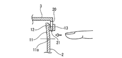
前記本体の側壁に上端面より左右一対の切込を入れて可撓片を設け、該可撓片の外面に係止爪を突設してランス形状のオスロック部を設け、かつ、前記左右一対の切込の外側外面から前記可撓片を跨ぐ保持枠を突設し、該保持枠と前記係止爪との間に挿入空間を設ける一方、前記蓋にロック穴を設けた係止枠からなるメスロック部を設けており、
前記メスロック部の係止枠を前記オスロック部と保持枠の間の挿入空間に押し込み、該係止枠の下枠を前記係止爪を乗り越えさせて係止爪の下面に係止し、該係止部分を前記保持枠で囲むとともに、該保持枠の下端から前記可撓片の下部を突出させる構成としていることを特徴とするロック構造を提供している。
図1乃至図6に実施形態を示す。
実施形態は自動車に配索するワイヤハーネスのプロテクタの本体と蓋とのロック構造に適用している。
まず、図4(A)に示すように、蓋3のメスロック部7の係止枠20の下枠21を本体2のオスロック部6と保持枠13の間の挿入空間15に挿入する。そのさい、下枠21の下部にテーパ部21bを設けているため、挿入空間15の上端側に係止爪12が突出しているが、比較的無理なく挿入できる。挿入した下枠21は、図4(B)(C)(D)(E)に示すように、係止爪12の傾斜した外面に下枠21の内面が摺接し、下枠21の外面は保持枠13の内面に摺接する。保持枠13は側壁2bに対して撓まないため、係止爪12の突出に応じて、係止爪12を突設した可撓片11を内側へ次第に大きく撓ませていく。図4(E)の位置で、係止爪12の最大突出部に下枠21が接触し、可撓片11の撓み量は最大となる。
前記オスロック部6とメスロック部7の構成は本実施形態と同様であるため、説明を省略する。
2 本体
3 蓋
6 オスロック部
7 メスロック部
10A、10B 切込
11 可撓片
12 係止爪
13 保持枠
15 挿入空間
20 係止枠
21 下枠
Claims (2)
- 樹脂成形品からなる本体と蓋のロック構造であって、
前記本体の側壁に上端面より左右一対の切込を入れて可撓片を設け、該可撓片の外面に係止爪を突設してランス形状のオスロック部を設け、かつ、前記左右一対の切込の外側外面から前記可撓片を跨ぐ保持枠を突設し、該保持枠と前記係止爪との間に挿入空間を設ける一方、前記蓋にロック穴を設けた係止枠からなるメスロック部を設けており、
前記メスロック部の係止枠を前記オスロック部と保持枠の間の挿入空間に押し込み、該係止枠の下枠を前記係止爪を乗り越えさせて係止爪の下面に係止し、該係止部分を前記保持枠で囲むとともに、該保持枠の下端から前記可撓片の下部を突出させる構成としていることを特徴とするロック構造。 - 前記本体と蓋はワイヤハーネスに外装するプロテクタの本体と蓋、または電気接続箱の本体と蓋である請求項1に記載のロック構造。
Priority Applications (1)
| Application Number | Priority Date | Filing Date | Title |
|---|---|---|---|
| JP2011029015A JP5454486B2 (ja) | 2011-02-14 | 2011-02-14 | ロック構造 |
Applications Claiming Priority (1)
| Application Number | Priority Date | Filing Date | Title |
|---|---|---|---|
| JP2011029015A JP5454486B2 (ja) | 2011-02-14 | 2011-02-14 | ロック構造 |
Publications (2)
| Publication Number | Publication Date |
|---|---|
| JP2012167736A JP2012167736A (ja) | 2012-09-06 |
| JP5454486B2 true JP5454486B2 (ja) | 2014-03-26 |
Family
ID=46972084
Family Applications (1)
| Application Number | Title | Priority Date | Filing Date |
|---|---|---|---|
| JP2011029015A Expired - Fee Related JP5454486B2 (ja) | 2011-02-14 | 2011-02-14 | ロック構造 |
Country Status (1)
| Country | Link |
|---|---|
| JP (1) | JP5454486B2 (ja) |
Families Citing this family (6)
| Publication number | Priority date | Publication date | Assignee | Title |
|---|---|---|---|---|
| CN102548263A (zh) * | 2010-12-15 | 2012-07-04 | 鸿富锦精密工业(深圳)有限公司 | 电子装置壳体 |
| JP6124772B2 (ja) * | 2013-10-31 | 2017-05-10 | 日本プラスト株式会社 | 樹脂部品の取付構造 |
| JP6439662B2 (ja) | 2015-11-18 | 2018-12-19 | 住友電装株式会社 | プロテクタ |
| JP7297387B2 (ja) * | 2019-06-19 | 2023-06-26 | 矢崎総業株式会社 | ロック構造 |
| JP7339184B2 (ja) * | 2020-02-28 | 2023-09-05 | 矢崎総業株式会社 | プロテクタ及びワイヤハーネス |
| KR102338390B1 (ko) * | 2020-07-15 | 2021-12-13 | 주식회사 경신 | 슬라이드 체결형 졍션박스 |
-
2011
- 2011-02-14 JP JP2011029015A patent/JP5454486B2/ja not_active Expired - Fee Related
Also Published As
| Publication number | Publication date |
|---|---|
| JP2012167736A (ja) | 2012-09-06 |
Similar Documents
| Publication | Publication Date | Title |
|---|---|---|
| JP5454486B2 (ja) | ロック構造 | |
| JP4743109B2 (ja) | 端子金具及びコネクタ | |
| CN103460534B (zh) | 存储盒和电接线盒 | |
| JP5739743B2 (ja) | 端子金具 | |
| JP5647491B2 (ja) | ホルダ係止構造 | |
| JP2011109826A (ja) | ワイヤハーネス用のプロテクタ | |
| JP5105516B2 (ja) | 電気接続箱ならびに収納箱の成型方法 | |
| JP6112423B2 (ja) | コネクタ、及びワイヤハーネスに対するコネクタの固定構造 | |
| JP4457917B2 (ja) | コネクタ | |
| CN112531400B (zh) | 电线盖 | |
| JP2009268163A (ja) | ワイヤハーネス用プロテクタ | |
| JP2014121224A (ja) | 電気接続箱 | |
| JP2006197659A (ja) | ワイヤハーネス用プロテクタ | |
| JP5412997B2 (ja) | 電気接続箱 | |
| JP4228848B2 (ja) | リテーナ付き端子収容部材、及び治具 | |
| JP5075725B2 (ja) | ロック構造及びターミナルキャップのカバーロック構造 | |
| JP4913557B2 (ja) | コネクタ押し込みプロテクタ | |
| JP6141817B2 (ja) | 端子金具及び端子金具の製造方法 | |
| JP2008282721A (ja) | コネクタ接続構造 | |
| JP4600293B2 (ja) | 電気接続箱 | |
| JP4232904B2 (ja) | ワイヤハーネス用プロテクタ | |
| JP4830803B2 (ja) | カバー付きコネクタ | |
| JP7736530B2 (ja) | 電気部品収容ボックス | |
| JP2009171816A (ja) | ワイヤハーネス用プロテクタ | |
| JP2005222758A (ja) | コネクタ |
Legal Events
| Date | Code | Title | Description |
|---|---|---|---|
| A621 | Written request for application examination |
Free format text: JAPANESE INTERMEDIATE CODE: A621 Effective date: 20130626 |
|
| A977 | Report on retrieval |
Free format text: JAPANESE INTERMEDIATE CODE: A971007 Effective date: 20131009 |
|
| TRDD | Decision of grant or rejection written | ||
| A01 | Written decision to grant a patent or to grant a registration (utility model) |
Free format text: JAPANESE INTERMEDIATE CODE: A01 Effective date: 20131210 |
|
| A61 | First payment of annual fees (during grant procedure) |
Free format text: JAPANESE INTERMEDIATE CODE: A61 Effective date: 20131223 |
|
| R150 | Certificate of patent or registration of utility model |
Ref document number: 5454486 Country of ref document: JP Free format text: JAPANESE INTERMEDIATE CODE: R150 Free format text: JAPANESE INTERMEDIATE CODE: R150 |
|
| LAPS | Cancellation because of no payment of annual fees |