JP5497645B2 - 車両用サスペンションアーム - Google Patents
車両用サスペンションアーム Download PDFInfo
- Publication number
- JP5497645B2 JP5497645B2 JP2010519739A JP2010519739A JP5497645B2 JP 5497645 B2 JP5497645 B2 JP 5497645B2 JP 2010519739 A JP2010519739 A JP 2010519739A JP 2010519739 A JP2010519739 A JP 2010519739A JP 5497645 B2 JP5497645 B2 JP 5497645B2
- Authority
- JP
- Japan
- Prior art keywords
- vehicle body
- upper wall
- arm
- portions
- vehicle
- Prior art date
- Legal status (The legal status is an assumption and is not a legal conclusion. Google has not performed a legal analysis and makes no representation as to the accuracy of the status listed.)
- Expired - Fee Related
Links
Images


Classifications
-
- B—PERFORMING OPERATIONS; TRANSPORTING
- B60—VEHICLES IN GENERAL
- B60G—VEHICLE SUSPENSION ARRANGEMENTS
- B60G7/00—Pivoted suspension arms; Accessories thereof
- B60G7/001—Suspension arms, e.g. constructional features
-
- B—PERFORMING OPERATIONS; TRANSPORTING
- B60—VEHICLES IN GENERAL
- B60G—VEHICLE SUSPENSION ARRANGEMENTS
- B60G2200/00—Indexing codes relating to suspension types
- B60G2200/10—Independent suspensions
- B60G2200/14—Independent suspensions with lateral arms
- B60G2200/142—Independent suspensions with lateral arms with a single lateral arm, e.g. MacPherson type
- B60G2200/1424—Independent suspensions with lateral arms with a single lateral arm, e.g. MacPherson type the lateral arm having an L-shape
-
- B—PERFORMING OPERATIONS; TRANSPORTING
- B60—VEHICLES IN GENERAL
- B60G—VEHICLE SUSPENSION ARRANGEMENTS
- B60G2202/00—Indexing codes relating to the type of spring, damper or actuator
- B60G2202/30—Spring/Damper and/or actuator Units
- B60G2202/31—Spring/Damper and/or actuator Units with the spring arranged around the damper, e.g. MacPherson strut
- B60G2202/312—The spring being a wound spring
-
- B—PERFORMING OPERATIONS; TRANSPORTING
- B60—VEHICLES IN GENERAL
- B60G—VEHICLE SUSPENSION ARRANGEMENTS
- B60G2206/00—Indexing codes related to the manufacturing of suspensions: constructional features, the materials used, procedures or tools
- B60G2206/01—Constructional features of suspension elements, e.g. arms, dampers, springs
- B60G2206/017—Constructional features of suspension elements, e.g. arms, dampers, springs forming an eye for the bushing
-
- B—PERFORMING OPERATIONS; TRANSPORTING
- B60—VEHICLES IN GENERAL
- B60G—VEHICLE SUSPENSION ARRANGEMENTS
- B60G2206/00—Indexing codes related to the manufacturing of suspensions: constructional features, the materials used, procedures or tools
- B60G2206/01—Constructional features of suspension elements, e.g. arms, dampers, springs
- B60G2206/10—Constructional features of arms
- B60G2206/122—Constructional features of arms the arm having L-shape
-
- B—PERFORMING OPERATIONS; TRANSPORTING
- B60—VEHICLES IN GENERAL
- B60G—VEHICLE SUSPENSION ARRANGEMENTS
- B60G2206/00—Indexing codes related to the manufacturing of suspensions: constructional features, the materials used, procedures or tools
- B60G2206/01—Constructional features of suspension elements, e.g. arms, dampers, springs
- B60G2206/80—Manufacturing procedures
- B60G2206/81—Shaping
- B60G2206/8102—Shaping by stamping
-
- B—PERFORMING OPERATIONS; TRANSPORTING
- B60—VEHICLES IN GENERAL
- B60G—VEHICLE SUSPENSION ARRANGEMENTS
- B60G2206/00—Indexing codes related to the manufacturing of suspensions: constructional features, the materials used, procedures or tools
- B60G2206/01—Constructional features of suspension elements, e.g. arms, dampers, springs
- B60G2206/80—Manufacturing procedures
- B60G2206/82—Joining
- B60G2206/8201—Joining by welding
Landscapes
- Engineering & Computer Science (AREA)
- Mechanical Engineering (AREA)
- Vehicle Body Suspensions (AREA)
Description
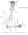
12 車体
17 アーム本体
17a ナックル取付部
17b 第1車体取付部(車体取付部)
17c 第2車体取付部(車体取付部)
17d 第1上壁部(上壁部)
17e 第2上壁部(上壁部)
17f 第3上壁部
17g 第1底壁部
17h 第2底壁部
17i 第3底壁部
17j 第1側壁部(側壁部)
17k 第2側壁部(側壁部)
17n 下壁部
17o 第1傾斜凸部
17p 第2傾斜凸部
17q 貫通孔
17s 凹部(凹凸部)
17u 凹部
A 第2、第3溶接部の上端間の距離
B 第2、第3溶接部の下端間の距離
w1 第1溶接部(溶接部)
w2 第2溶接部(溶接部)
w3 第3溶接部(溶接部)
Claims (12)
- 金属板をプレス加工して構成されるアーム本体(17)が、ナックル(11)が取り付けられるナックル取付部(17a)と、前記ナックル取付部(17a)の車幅方向内側に設けられて車体(12)に取り付けられる第1車体取付部(17b)と、前記第1車体取付部(17b)の車体後方側に設けられて車体(12)に取り付けられる第2車体取付部(17c)とを備える車両用サスペンションアームであって、
前記アーム本体(17)の車体(12)への取付状態において、前記第1車体取付部(17b)から前記第2車体取付部(17c)へと略水平に延びる第1上壁部(17d)と、
前記アーム本体(17)の車体(12)への取付状態において、前記第2車体取付部(17c)から前記ナックル取付部(17a)へと略水平に延びる第2上壁部(17e)と、
前記アーム本体(17)の車体(12)への取付状態において、前記ナックル取付部(17a)から前記第1車体取付部(17b)へと略水平に延びる第3上壁部(17f)と、
前記第1、第2上壁部(17d,17e)よりも低い位置にあって両上壁部(17d,17e)を接続する第1底壁部(17g)と、
前記第2、第3上壁部(17e,17f)よりも低い位置にあって両上壁部(17e,17f)を接続する第2底壁部(17h)と、
前記第1底壁部(17g)の前記第1車体取付部(17b)側の端部に上向きに膨出するように形成され、前記第1上壁部(17d)から前記第2上壁部(17e)に向かって高さが次第に減少する第1傾斜凸部(17o)と、
前記第2底壁部(17h)の前記第1車体取付部(17b)側の端部に上向きに膨出するように形成され、前記第3上壁部(17f)から前記第2上壁部(17e)に向かって高さが次第に減少する第2傾斜凸部(17p)と、
を備えることを特徴とする車両用サスペンションアーム。 - 前記第1傾斜凸部(17o)は、前記第1上壁部(17d)から前記第2上壁部(17e)に向かって幅が次第に減少することを特徴とする、請求項1に記載の車両用サスペンションアーム。
- 前記第2傾斜凸部(17p)は、前記第3上壁部(17f)から前記第2上壁部(17e)に向かって幅が次第に減少することを特徴とする、請求項1に記載の車両用サスペンションアーム。
- 前記アーム本体(17)は、前記第1、第2傾斜凸部(17o,17p)に挟まれた位置に前記第1、第2底壁部(17g,17h)に略同じ高さで連なる第3底壁部(17i)を備え、前記第3底壁部(17i)に貫通孔(17q)が形成されることを特徴とする、請求項1に記載の車両用サスペンションアーム。
- 前記車体取付部(17b)の外面が前記アーム本体(17)の端縁に形成した溶接部(w1〜w3)に溶接により固定され、
前記アーム本体(17)の溶接部(w1〜w3)は、前記アーム本体(17)の車体(12)への取付状態において略水平に延びる第1溶接部(w1)と、前記第1溶接部(w1)の両端から下向きに延びる第2、第3溶接部(w2,w3)とよりなり、前記第2、第3溶接部(w2,w3)は、それらの上端間の距離(A)に対して下端間の距離(B)が大きく設定されることを特徴とする、請求項1に記載の車両用サスペンションアーム。 - 前記第3溶接部(w3)は、前記第1溶接部(w1)に連なる部分から下向きに延びながら、前記第2溶接部(w2)から離間する方向に湾曲することを特徴とする、請求項5に記載の車両用サスペンションアーム。
- 前記アーム本体(17)は、第1車体取付部(17b)としての前記車体取付部の後方に第2車体取付部(17c)を備えており、
前記アーム本体(17)の前記第1、第2車体取付部(17b,17c)に挟まれた部分は、第1、第2上壁部(17d,17e)と、前記第1、第2上壁部(17d,17e)の両側縁を下向きに折り曲げた第1、第2側壁部(17j,17k)とを備え、
前記第1側壁部(17j)は前記第1車体取付部(17b)側が前記第2側壁部(17k)から離間する方向に湾曲して前記第3溶接部(w3)に連続することを特徴とする、請求項5に記載の車両用サスペンションアーム。 - 前記第1上壁部(17d)と前記第1側壁部(17j)とが連なる部分に、下向きに凹む凹部(17u)が形成されることを特徴とする、請求項7に記載の車両用サスペンションアーム。
- 前記アーム本体(17)はナックル(11)が取り付けられるナックル取付部(17a)と車体(12)に取り付けられる第1、第2車体取付部(17b,17c)とを備え、前記ナックル取付部(17a)および前記第1、第2車体取付部(17b,17c)の少なくとも一つの周縁部に、凹凸部(17s)が形成されることを特徴とする、請求項1に記載の車両用サスペンションアーム。
- 前記凹凸部(17s)の形状は略多角形あるいは略円形であることを特徴とする、請求項9に記載の車両用サスペンションアーム。
- 前記アーム本体(17)は、それを車体(12)に取り付けた状態で略水平方向に延びる第1、第2上壁部(17d,17e)と、前記第1、第2上壁部(17d,17e)の周縁を下向きに折り曲げた第1、第2側壁部(17j,17k)とを備え、前記凹凸部(17s)が形成される前記ナックル取付部(17a)および前記第1、第2車体取付部(17b,17c)のうち、少なくとも一つの近傍では、その他の部分に比べて前記第1、第2側壁部(17j,17k)の高さが小さく形成され、前記凹凸部(17s)は前記第1、第2上壁部(17d,17e)および前記第1、第2側壁部(17j,17k)の境界に形成されることを特徴とする、請求項9に記載の車両用サスペンションアーム。
- 前記アーム本体(17)は、それを車体(12)に取り付けた状態で略水平方向に延びる第1、第2上壁部(17d,17e)と、前記第1、第2上壁部(17d,17e)の周縁を下向きに折り曲げた第1、第2側壁部(17j,17k)と、前記第1、第2側壁部(17j,17k)のうちの少なくとも一部で、前記第1、第2上壁部(17d,17e)と連続しない端部を折り曲げて形成される下壁部(17n)を備え、前記第1、第2上壁部(17d,17e)および前記第1、第2側壁部(17j,17k)の境界のうち、前記下壁部(17n)が設けられている部分と設けられていない部分との境目の位置に前記凹凸部(17s)が形成されることを特徴とする、請求項9に記載の車両用サスペンションアーム。
Priority Applications (1)
| Application Number | Priority Date | Filing Date | Title |
|---|---|---|---|
| JP2010519739A JP5497645B2 (ja) | 2008-07-10 | 2009-06-29 | 車両用サスペンションアーム |
Applications Claiming Priority (8)
| Application Number | Priority Date | Filing Date | Title |
|---|---|---|---|
| JP2008180752 | 2008-07-10 | ||
| JP2008180752 | 2008-07-10 | ||
| JP2008180753 | 2008-07-10 | ||
| JP2008180753 | 2008-07-10 | ||
| JP2008183364 | 2008-07-15 | ||
| JP2008183364 | 2008-07-15 | ||
| PCT/JP2009/061855 WO2010004899A1 (ja) | 2008-07-10 | 2009-06-29 | 車両用サスペンションアーム |
| JP2010519739A JP5497645B2 (ja) | 2008-07-10 | 2009-06-29 | 車両用サスペンションアーム |
Publications (2)
| Publication Number | Publication Date |
|---|---|
| JPWO2010004899A1 JPWO2010004899A1 (ja) | 2012-01-05 |
| JP5497645B2 true JP5497645B2 (ja) | 2014-05-21 |
Family
ID=41507015
Family Applications (1)
| Application Number | Title | Priority Date | Filing Date |
|---|---|---|---|
| JP2010519739A Expired - Fee Related JP5497645B2 (ja) | 2008-07-10 | 2009-06-29 | 車両用サスペンションアーム |
Country Status (6)
| Country | Link |
|---|---|
| US (1) | US8251386B2 (ja) |
| EP (2) | EP2295269B1 (ja) |
| JP (1) | JP5497645B2 (ja) |
| CN (1) | CN102066139B (ja) |
| BR (1) | BRPI0913995A2 (ja) |
| WO (1) | WO2010004899A1 (ja) |
Families Citing this family (29)
| Publication number | Priority date | Publication date | Assignee | Title |
|---|---|---|---|---|
| DE102007049113B4 (de) * | 2007-10-12 | 2016-12-15 | Volkswagen Ag | Einschaliger Querlenker |
| IT1398384B1 (it) * | 2009-02-05 | 2013-02-22 | Sistemi Sospensioni Spa | Braccio oscillante per sospensione di veicolo e procedimento per la sua realizzazione |
| KR101382340B1 (ko) * | 2009-11-23 | 2014-04-08 | 기아자동차 주식회사 | 멀티 링크 현가장치의 컨트롤 아암 |
| DE102010024634A1 (de) * | 2010-06-22 | 2011-12-22 | Benteler Automobiltechnik Gmbh | Kraftfahrzeuglenker |
| DE202011000609U1 (de) * | 2011-03-17 | 2012-06-20 | Kirchhoff Automotive Deutschland Gmbh | Lenker für eine Fahrzeugradaufhängung |
| JP5299470B2 (ja) * | 2011-05-16 | 2013-09-25 | 日産自動車株式会社 | サスペンション構造、サスペンションリンク形成方法 |
| DE102012104909A1 (de) * | 2012-06-06 | 2013-12-12 | Benteler Automobiltechnik Gmbh | Querlenker sowie Verfahren zum Herstellen des Querlenkers |
| JP2014118094A (ja) * | 2012-12-19 | 2014-06-30 | Mitsubishi Motors Corp | サスペンションアーム |
| CN103909797B (zh) * | 2012-12-29 | 2016-06-01 | 重庆长安汽车股份有限公司 | 一种用于独立悬架横摆臂的复合式铰链结构 |
| US8870205B2 (en) * | 2013-03-11 | 2014-10-28 | Nissan North America, Inc. | Vehicle front suspension |
| JP6136640B2 (ja) * | 2013-06-27 | 2017-05-31 | スズキ株式会社 | フロントサスペンション装置 |
| JP6236291B2 (ja) * | 2013-11-12 | 2017-11-22 | 豊田鉄工株式会社 | サスペンションアームの製造方法 |
| JP5771320B2 (ja) * | 2013-12-19 | 2015-08-26 | 株式会社神戸製鋼所 | 自動車足回り部品 |
| EP2918430B1 (de) | 2014-03-12 | 2017-05-03 | Autotech Engineering Deutschland GmbH | Fahrwerkslenker für ein Kraftfahrzeug |
| ES2675327T3 (es) * | 2014-04-02 | 2018-07-10 | Autotech Engineering Deutschland GmbH | Procedimiento para fabricar un brazo de tren de rodaje |
| DE112016001710T5 (de) * | 2015-04-13 | 2018-01-04 | F-Tech Inc. | Aufhängungsarm für ein Fahrzeug |
| KR101732066B1 (ko) * | 2015-04-29 | 2017-05-08 | 주식회사 일진 | 치핑에 의한 도장면 손상 방지 구조를 가지는 하이브리드 암 |
| CN105835642A (zh) * | 2016-04-11 | 2016-08-10 | 重庆长安汽车股份有限公司 | 一种汽车悬架摆臂结构 |
| DE102016211675B4 (de) | 2016-06-29 | 2025-07-17 | Ford Global Technologies, Llc | Querlenker für ein Kraftfahrzeug |
| JP6943214B2 (ja) * | 2018-03-30 | 2021-09-29 | トヨタ自動車株式会社 | トレーリングアーム |
| JP6934276B2 (ja) * | 2018-09-28 | 2021-09-15 | ダイハツ工業株式会社 | サスペンションアーム及び車両の懸架装置 |
| JP7068124B2 (ja) * | 2018-09-28 | 2022-05-16 | 本田技研工業株式会社 | 車両用サスペンションアーム |
| JP7286082B2 (ja) * | 2019-04-24 | 2023-06-05 | 三菱自動車工業株式会社 | 自動車用サスペンションアーム |
| KR102323790B1 (ko) * | 2019-12-13 | 2021-11-09 | 주식회사 포스코 | 서스펜션의 트레일링 암 |
| JP7051916B2 (ja) * | 2020-02-12 | 2022-04-11 | 株式会社リケン | 車両用ナックル |
| CN115867397A (zh) * | 2020-07-09 | 2023-03-28 | 日本制铁株式会社 | 翻边加工方法、翻边加工品的制造方法、翻边加工用模具、翻边加工装置以及翻边加工品 |
| CN116018280B (zh) * | 2020-09-29 | 2025-08-22 | 株式会社万 | 车辆悬架用结构体及其制造方法 |
| JP7569535B2 (ja) * | 2021-03-29 | 2024-10-18 | 株式会社戸田レーシング | 車輪モジュール |
| KR102844873B1 (ko) * | 2023-12-26 | 2025-08-11 | (주)티앤지 | 차량 현가장치용 컨트롤 암 구조체 및 이의 제조방법 |
Family Cites Families (20)
| Publication number | Priority date | Publication date | Assignee | Title |
|---|---|---|---|---|
| JPS60121908U (ja) * | 1984-01-26 | 1985-08-17 | 三菱自動車工業株式会社 | 車両のサスペンシヨン装置 |
| JP2531273Y2 (ja) * | 1987-03-28 | 1997-04-02 | 三菱自動車工業株式会社 | 3リンクサスペンシヨン装置 |
| US4953278A (en) * | 1987-08-07 | 1990-09-04 | Shim-A-Line, Inc. | Method for adjusting alignment of a wheel |
| JP3159288B2 (ja) * | 1994-07-20 | 2001-04-23 | 本田技研工業株式会社 | サスペンションアームの製造方法 |
| JPH08332820A (ja) * | 1995-06-12 | 1996-12-17 | Toyota Motor Corp | サスペンションアーム |
| JPH0920115A (ja) | 1995-07-04 | 1997-01-21 | Honda Motor Co Ltd | 車両用サスペンションアーム |
| JP3191654B2 (ja) | 1995-08-30 | 2001-07-23 | トヨタ自動車株式会社 | サスペンションアーム |
| JP3505899B2 (ja) * | 1996-03-04 | 2004-03-15 | トヨタ自動車株式会社 | 車両用サスペンションアーム |
| DE20009695U1 (de) | 2000-05-31 | 2000-08-24 | Benteler Ag, 33104 Paderborn | Lenker für ein Kraftfahrzeug |
| JP3725031B2 (ja) | 2001-01-12 | 2005-12-07 | 本田技研工業株式会社 | サスペンションアーム |
| JP2003002025A (ja) | 2001-06-22 | 2003-01-08 | Suzuki Motor Corp | サスペンションアーム構造 |
| FR2841500B1 (fr) * | 2002-06-28 | 2006-01-06 | Auto Chassis Int | Bras monotole de suspension avant de vehicule automobile et procede d'obtention d'un tel bras |
| JP2004090750A (ja) * | 2002-08-30 | 2004-03-25 | Suzuki Motor Corp | サスペンションアーム |
| JP4264933B2 (ja) | 2003-01-24 | 2009-05-20 | 株式会社神戸製鋼所 | サスペンションアーム及びその製造方法 |
| DE112006002159T5 (de) * | 2005-08-17 | 2008-10-23 | F. Tech Incorporation | Fahrzeug-Aufhängungslenker |
| US7793954B2 (en) * | 2007-06-22 | 2010-09-14 | Radar Industries, Inc. | Suspension system for a vehicle |
| US7703783B2 (en) * | 2008-09-17 | 2010-04-27 | Honda Motor Co., Ltd. | Suspension arm having a shaft projecting therefrom and method for press fitting the shaft into a bore of another member |
| JP2010111226A (ja) * | 2008-11-05 | 2010-05-20 | F Tech:Kk | 車両用l型サスペンションアーム |
| JP5363065B2 (ja) * | 2008-11-05 | 2013-12-11 | 株式会社エフテック | 車両用l型サスペンションアーム |
| DE102010007944A1 (de) * | 2010-02-12 | 2011-08-18 | Benteler Automobiltechnik GmbH, 33102 | Querlenker und Verfahren zur Herstellung eines Querlenkers |
-
2009
- 2009-06-29 JP JP2010519739A patent/JP5497645B2/ja not_active Expired - Fee Related
- 2009-06-29 CN CN200980123468.7A patent/CN102066139B/zh not_active Expired - Fee Related
- 2009-06-29 BR BRPI0913995A patent/BRPI0913995A2/pt not_active Application Discontinuation
- 2009-06-29 US US12/997,337 patent/US8251386B2/en not_active Expired - Fee Related
- 2009-06-29 WO PCT/JP2009/061855 patent/WO2010004899A1/ja not_active Ceased
- 2009-06-29 EP EP09794345A patent/EP2295269B1/en not_active Not-in-force
- 2009-06-29 EP EP12181303.4A patent/EP2529959B1/en not_active Not-in-force
Also Published As
| Publication number | Publication date |
|---|---|
| EP2295269A4 (en) | 2011-07-27 |
| EP2295269B1 (en) | 2012-09-05 |
| BRPI0913995A2 (pt) | 2015-10-20 |
| US20110115186A1 (en) | 2011-05-19 |
| CN102066139A (zh) | 2011-05-18 |
| EP2295269A1 (en) | 2011-03-16 |
| EP2529959A2 (en) | 2012-12-05 |
| EP2529959A3 (en) | 2013-03-20 |
| EP2529959B1 (en) | 2014-04-30 |
| WO2010004899A1 (ja) | 2010-01-14 |
| US8251386B2 (en) | 2012-08-28 |
| JPWO2010004899A1 (ja) | 2012-01-05 |
| CN102066139B (zh) | 2013-05-08 |
Similar Documents
| Publication | Publication Date | Title |
|---|---|---|
| JP5497645B2 (ja) | 車両用サスペンションアーム | |
| JP6304503B2 (ja) | 車両の側部車体構造 | |
| JP5212498B2 (ja) | 車体後部構造 | |
| JP6845539B2 (ja) | 自動車の後部サスペンション構造 | |
| JP5838603B2 (ja) | 車体後部構造 | |
| JP5968971B2 (ja) | 車体後部構造 | |
| JP5734030B2 (ja) | 自動車の車体前部構造 | |
| CN212579544U (zh) | 汽车悬架的控制臂、悬架和汽车 | |
| JP6660197B2 (ja) | 自動車の車体構造 | |
| JP6331589B2 (ja) | トレーリングアーム取付部構造 | |
| JP2001310756A (ja) | 自動車の車体前部構造 | |
| JP6428820B2 (ja) | 自動車の後部整流構造 | |
| JP6735458B2 (ja) | トーションビーム式サスペンション及びそれに使用するトレーリングアーム | |
| JP4529569B2 (ja) | 車体後部構造 | |
| JP4479473B2 (ja) | 自動車車体の後部構造 | |
| JP2018020643A (ja) | ホイールハウス構造 | |
| JP7415108B2 (ja) | 車両用ロアアーム | |
| JP4457643B2 (ja) | 車両のサスペンション支持部構造 | |
| JP2019108072A (ja) | 自動車用クロスメンバ構造 | |
| JP2012046112A (ja) | 車体構造 | |
| JP5169078B2 (ja) | 車体構造 | |
| JP2001150999A (ja) | 車両用アシストグリップ取付構造 | |
| JPH08324456A (ja) | 車体前部構造 | |
| JPH076003Y2 (ja) | 車両のサスペンション装置 | |
| JP4271189B2 (ja) | 車両のサブフレーム |
Legal Events
| Date | Code | Title | Description |
|---|---|---|---|
| A621 | Written request for application examination |
Free format text: JAPANESE INTERMEDIATE CODE: A621 Effective date: 20111130 |
|
| A131 | Notification of reasons for refusal |
Free format text: JAPANESE INTERMEDIATE CODE: A131 Effective date: 20130911 |
|
| A521 | Request for written amendment filed |
Free format text: JAPANESE INTERMEDIATE CODE: A523 Effective date: 20131101 |
|
| TRDD | Decision of grant or rejection written | ||
| A01 | Written decision to grant a patent or to grant a registration (utility model) |
Free format text: JAPANESE INTERMEDIATE CODE: A01 Effective date: 20140219 |
|
| A61 | First payment of annual fees (during grant procedure) |
Free format text: JAPANESE INTERMEDIATE CODE: A61 Effective date: 20140306 |
|
| R150 | Certificate of patent or registration of utility model |
Ref document number: 5497645 Country of ref document: JP Free format text: JAPANESE INTERMEDIATE CODE: R150 |
|
| LAPS | Cancellation because of no payment of annual fees |