JP5520657B2 - CHARGE RATE ESTIMATION METHOD, CHARGE RATE ESTIMATION DEVICE, AND SECONDARY BATTERY POWER SUPPLY SYSTEM - Google Patents
CHARGE RATE ESTIMATION METHOD, CHARGE RATE ESTIMATION DEVICE, AND SECONDARY BATTERY POWER SUPPLY SYSTEM Download PDFInfo
- Publication number
- JP5520657B2 JP5520657B2 JP2010079617A JP2010079617A JP5520657B2 JP 5520657 B2 JP5520657 B2 JP 5520657B2 JP 2010079617 A JP2010079617 A JP 2010079617A JP 2010079617 A JP2010079617 A JP 2010079617A JP 5520657 B2 JP5520657 B2 JP 5520657B2
- Authority
- JP
- Japan
- Prior art keywords
- voltage
- voltage measurement
- measurement value
- secondary battery
- value
- Prior art date
- Legal status (The legal status is an assumption and is not a legal conclusion. Google has not performed a legal analysis and makes no representation as to the accuracy of the status listed.)
- Active
Links
Images


Classifications
-
- G—PHYSICS
- G01—MEASURING; TESTING
- G01R—MEASURING ELECTRIC VARIABLES; MEASURING MAGNETIC VARIABLES
- G01R31/00—Arrangements for testing electric properties; Arrangements for locating electric faults; Arrangements for electrical testing characterised by what is being tested not provided for elsewhere
- G01R31/36—Arrangements for testing, measuring or monitoring the electrical condition of accumulators or electric batteries, e.g. capacity or state of charge [SoC]
- G01R31/382—Arrangements for monitoring battery or accumulator variables, e.g. SoC
- G01R31/3835—Arrangements for monitoring battery or accumulator variables, e.g. SoC involving only voltage measurements
Landscapes
- Physics & Mathematics (AREA)
- General Physics & Mathematics (AREA)
- Secondary Cells (AREA)
- Tests Of Electric Status Of Batteries (AREA)
- Charge And Discharge Circuits For Batteries Or The Like (AREA)
Description
本発明は、負荷に電力を供給する二次電池の充電率を推定する充電率推定方法及び充電率推定装置の技術分野に関するものである。 The present invention relates to a technical field of a charging rate estimation method and a charging rate estimation device that estimate a charging rate of a secondary battery that supplies power to a load.
従来より、自動車等に搭載される鉛蓄電池等の二次電池については、残存する充電率を正確に知ることが要請されている。二次電池においては、一般に、充電率と安定時の開回路電圧(OCV;Open Circuit Voltage)との間に相関があるため、開回路電圧を求めることにより充電率を推定することができる。しかし、二次電池の開回路電圧は充電又は放電を行っていない状態で行う必要がある上に、充電又は放電の終了後に開回路電圧が安定するまでには長い時間を要している。そこで、開回路電圧の時間特性を近似する関数(電圧特性式)を用いて、開回路電圧の収束値を求める方法が種々提案されている(例えば、特許文献1〜3)。
Conventionally, for secondary batteries such as lead-acid batteries mounted on automobiles or the like, it is required to accurately know the remaining charge rate. Generally, in a secondary battery, since there is a correlation between a charging rate and an open circuit voltage (OCV) at a stable time, the charging rate can be estimated by obtaining an open circuit voltage. However, the open circuit voltage of the secondary battery needs to be performed in a state where charging or discharging is not performed, and it takes a long time for the open circuit voltage to become stable after completion of charging or discharging. Therefore, various methods for obtaining the convergence value of the open circuit voltage using a function (voltage characteristic equation) that approximates the time characteristic of the open circuit voltage have been proposed (for example,
上記の従来の方法では、いずれも開回路電圧の電圧特性式が調整パラメータを有しており、この調整パラメータを短期間だけ測定した開回路電圧の測定値を用いて決定している。そして、決定された調整パラメータを適用した電圧特性式を用いて、開回路電圧の収束値を求めている。 In any of the above conventional methods, the voltage characteristic equation of the open circuit voltage has an adjustment parameter, and this adjustment parameter is determined using the measured value of the open circuit voltage measured only for a short period. And the convergence value of the open circuit voltage is calculated | required using the voltage characteristic formula which applied the determined adjustment parameter.
上記従来の方法で二次電池の開回路電圧の収束値を求める場合、その精度は電圧特性式の精度に依存する。一般には、電圧特性式に多項式関数や対数関数などが用いられるが、これらの関数は二次電池の開回路電圧の時間特性を高精度で近似するのが困難なため、開回路電圧の収束値の誤差が大きくなってしまう。 When the convergence value of the open circuit voltage of the secondary battery is obtained by the conventional method, the accuracy depends on the accuracy of the voltage characteristic equation. Generally, a polynomial function or a logarithmic function is used in the voltage characteristic formula. However, since these functions are difficult to accurately approximate the time characteristics of the open circuit voltage of the secondary battery, the convergence value of the open circuit voltage is used. The error will increase.
これに対し特許文献4では、二次電池の開回路電圧の近似計算に4次以上の指数減衰関数を用いており、これにより開回路電圧を高い精度で近似できるようにし、充電率を高精度に推定できるようにしている。二次電池の開回路電圧の近似計算に、4次以上の指数減衰関数のような複雑な非線形関数を用いる場合には、電圧測定値を用いて調整パラメータを最適化する際、最小二乗法の最適解をガウス-ニュートン法やレーベンベルグ-マルカート法のような逐次演算を解くか、カルマン-フィルタ演算のようなフィルタリング演算を行なう必要がある。 On the other hand, in Patent Document 4, an exponential decay function of the fourth order or higher is used for the approximate calculation of the open circuit voltage of the secondary battery, so that the open circuit voltage can be approximated with high accuracy, and the charging rate is highly accurate. Can be estimated. When a complex nonlinear function such as an exponential decay function of the fourth order or higher is used for the approximate calculation of the open circuit voltage of the secondary battery, when the adjustment parameter is optimized using the voltage measurement value, the least square method is used. It is necessary to solve the optimal solution by a sequential operation such as Gauss-Newton method or Levenberg-Marquardt method or a filtering operation such as Kalman-filter operation.
調整パラメータを最適化する上記の何れの方法を用いた場合でも、調整パラメータの初期値を設定する必要があり、その初期値によっては、計算が発散して調整パラメータの収束値が得られない可能性や、得られたとしても非常に長い時間がかかってしまうといった問題があった。特許文献4では、調整パラメータの収束値を短時間でかつ安定的に決定する方法が提案されている。 Regardless of the method used to optimize the adjustment parameter, it is necessary to set the initial value of the adjustment parameter. Depending on the initial value, the calculation may diverge and the convergence value of the adjustment parameter may not be obtained. There was a problem that it took a very long time even if it was obtained. Patent Document 4 proposes a method for stably determining a convergence value of an adjustment parameter in a short time.
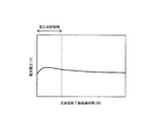
しかしながら、上記従来の二次電池の充電率推定方法では、以下のような問題があった。特許文献4の方法では、データ取得期間の初期の電圧測定値と終了直前の電圧測定値のみを用いて調整パラメータの初期値を一意的に決定している。そのため、初期値として適切でない値が設定されてしまう場合があり、その場合には調整パラメータの最適計算が収束しないことがあった。すなわち、二次電池の充放電停止後の開回路電圧の変化が、あらかじめ想定した電圧プロファイル(徐々に低下または上昇)の範囲であれば調整パラメータの最適化が可能であるが、実車両での充放電履歴は様々なため、想定範囲外の電圧プロファイルを示すことがある。一例として、図9に示すように、電圧測定期間の途中で電圧測定値の変化が反転するような場合がある。特許文献4の方法では、このような電圧プロファイルの場合でも、データ取得期間の初期の電圧測定値と終了直前の電圧測定値とから調整パラメータの初期値を決定しているため、調整パラメータの最適化が収束しないことがあった。 However, the conventional secondary battery charging rate estimation method has the following problems. In the method of Patent Document 4, the initial value of the adjustment parameter is uniquely determined using only the initial voltage measurement value in the data acquisition period and the voltage measurement value immediately before the end of the data acquisition period. Therefore, an inappropriate value may be set as the initial value, and in this case, the optimal calculation of the adjustment parameter may not converge. In other words, the adjustment parameters can be optimized if the change in the open circuit voltage after the secondary battery stops charging and discharging is in the range of the voltage profile (gradual decrease or increase) assumed in advance. Since the charge / discharge history varies, a voltage profile outside the assumed range may be shown. As an example, as shown in FIG. 9, there is a case where the change in the voltage measurement value is reversed during the voltage measurement period. In the method of Patent Document 4, even in the case of such a voltage profile, the initial value of the adjustment parameter is determined from the initial voltage measurement value in the data acquisition period and the voltage measurement value immediately before the end of the data acquisition period. In some cases, the process did not converge.
そこで、本発明はこれらの問題を解決するためになされたものであり、二次電池の開回路電圧の時間変化を高精度で近似できる電圧特性式の調整パラメータの初期値を好適に設定することにより、調整パラメータの収束値を短時間でかつ安定的に決定して充電率を推定することができる充電率推定方法、充電率推定装置及び二次電池電源システムを提供することを目的とする。 Accordingly, the present invention has been made to solve these problems, and preferably sets the initial value of the adjustment parameter of the voltage characteristic equation that can accurately approximate the time change of the open circuit voltage of the secondary battery. Accordingly, an object of the present invention is to provide a charging rate estimation method, a charging rate estimation device, and a secondary battery power supply system that can estimate the charging rate by stably determining the convergence value of the adjustment parameter in a short time.
この発明の充電率推定方法の第1の態様は、充放電終了後の二次電池の開回路電圧(OCV;Open Circuit Voltage)の時間変化を、調整パラメータを有する電圧特性式で近似し、前記電圧特性式から前記二次電池の安定時の開回路電圧を算出して前記二次電池の充電率を推定する充電率推定方法であって、前記二次電池の充放電終了後の所定のデータ取得期間中に所定の周期で前記二次電池の開回路電圧の測定値(以下、電圧測定値とする)をm個(mは自然数)取得し、前記m個の電圧測定値から所定の選択タイミングにおける電圧測定値を選択して選択電圧測定値とし、前記選択電圧測定値及び前記選択タイミングに基づいて前記調整パラメータの初期値を算出し、前記電圧特性式で算出した開回路電圧と前記m個の電圧測定値との誤差が最小となるように前記調整パラメータを前記初期値から漸次修正しながらその収束値を算出し、前記調整パラメータの収束値を前記電圧特性式に用いて前記安定時の開回路電圧を算出し、前記安定時の開回路電圧から前記二次電池の充電率を推定することを特徴とする。 According to a first aspect of the charging rate estimation method of the present invention, the time variation of the open circuit voltage (OCV) of the secondary battery after the end of charge / discharge is approximated by a voltage characteristic equation having an adjustment parameter, A charge rate estimation method for estimating a charge rate of the secondary battery by calculating an open circuit voltage of the secondary battery at a stable time from a voltage characteristic equation, wherein the predetermined data after the charge / discharge of the secondary battery is completed During the acquisition period, m measurement values (hereinafter referred to as voltage measurement values) of the open circuit voltage of the secondary battery are acquired at a predetermined cycle (m is a natural number), and a predetermined selection is made from the m voltage measurement values. A voltage measurement value at a timing is selected as a selection voltage measurement value, an initial value of the adjustment parameter is calculated based on the selection voltage measurement value and the selection timing, and the open circuit voltage calculated by the voltage characteristic equation and the m The error from the voltage measurement The convergence parameter is calculated while gradually adjusting the adjustment parameter from the initial value so that the adjustment parameter is calculated, and the convergence value of the adjustment parameter is used in the voltage characteristic equation to calculate the open circuit voltage at the time of stabilization, The charging rate of the secondary battery is estimated from the open circuit voltage at the time.
この発明の充電率推定方法の他の態様は、前記調整パラメータを{Ai}(i=1〜n)、{Bi}(i=1〜n)、及びVcとし、nを4以上の整数、tを充放電終了からの経過時間とするとき、前記電圧特定式は、
V(t)=A1・exp(B1・t))+A2・exp(B2・t)+・・・
+An・exp(Bn・t)+Vc
で与えられ、{bi}(i=1〜(n−1))を1<b1<b2<・・・<bn−1を満たし、前記選択タイミングに対応するように事前に設定された整数列とするとき、前記調整パラメータ{Ai}(i=1〜n)、{Bi}(i=1〜n)、及びVcのそれぞれの前記初期値{A0i}(i=1〜n)、{B0i}(i=1〜n)、及びV0cが、前記整数列{bi}(i=1〜(n−1))から決定される前記選択タイミングにおける前記選択電圧測定値を用いて算出されることを特徴とする。
In another aspect of the charging rate estimation method of the present invention, the adjustment parameters are {A i } (i = 1 to n), {B i } (i = 1 to n), and Vc, and n is 4 or more. When the integer, t is the elapsed time from the end of charge / discharge, the voltage specifying formula is
V (t) = A 1 · exp (B 1 · t)) + A 2 · exp (B 2 · t) +.
+ A n · exp (B n · t) + Vc
And {b i } (i = 1 to (n−1)) is set in advance so as to satisfy 1 <b 1 <b 2 <... <B n−1 and correspond to the selection timing. The initial values {A0 i } (i =) of the adjustment parameters {A i } (i = 1 to n), {B i } (i = 1 to n), and Vc. 1 to n), {B0 i } (i = 1 to n), and V0c are determined at the selection timing determined from the integer sequence {b i } (i = 1 to (n−1)). It is calculated using a measured value.
この発明の充電率推定方法の他の態様は、前記整数列{bi}(i=1〜(n−1))は、
(b1−1)<(b2―b1)<・・・<(bn−1−bn−2)<(m−bn−1)を満たすことを特徴とする。
In another aspect of the charging rate estimation method of the present invention, the integer sequence {b i } (i = 1 to (n−1)) is
(B 1 -1) <(b 2 −b 1 ) <... <(B n−1 −b n−2 ) <(m−b n−1 ).
この発明の充電率推定方法の他の態様は、前記電圧測定値を{VMj}(j=1〜m)、前記電圧測定値の取得周期をΔt、Cを事前に設定された実数とするとき、前記選択電圧測定値として、前記データ取得期間の最初に取得される電圧測定値VM1、前記整数列{bi}(i=1〜(n−1))を前記選択タイミングとする電圧測定値{VMk}(k=bi;i=1〜(n−1))、及びデータ取得期間の最後に取得される選択電圧測定値VMmを選択し、前記初期値{A0i}(i=1〜n)、{B0i}(i=1〜n)、及びV0cを、
A01=VM1−VMk (k=b1)
A0i=VMkk−VMk (kk=bi−1、k=bi;i=2〜(n−1))
A0n=VMk−VMm (k=bn−1)
B0i=−1/((bi−1)×Δt×C) (i=1〜(n−1))
B0n=−1/((m−1)×Δt×C)
V0c=VMm
で算出することを特徴とする。
According to another aspect of the charging rate estimation method of the present invention, the voltage measurement value is {VM j } (j = 1 to m), the acquisition period of the voltage measurement value is Δt, and C is a preset real number. Then, as the selection voltage measurement value, the voltage measurement value VM 1 acquired at the beginning of the data acquisition period and the integer sequence {b i } (i = 1 to (n−1)) as the selection timing voltage The measurement value {VM k } (k = b i ; i = 1 to (n−1)) and the selected voltage measurement value VM m acquired at the end of the data acquisition period are selected, and the initial value {A0 i } (I = 1 to n), {B0 i } (i = 1 to n), and V0c,
A0 1 = VM 1 −VM k (k = b 1 )
A0 i = VM kk −VM k (kk = b i−1 , k = b i ; i = 2 to (n−1))
A0 n = VM k -VM m (k = b n-1 )
B0 i = −1 / ((b i −1) × Δt × C) (i = 1 to (n−1))
B0 n = −1 / ((m−1) × Δt × C)
V0c = VM m
It is characterized by calculating by.
この発明の充電率推定方法の他の態様は、前記電圧測定値{VMj}(j=1〜m)が前記データ取得期間中に最大または最小となるピーク値VMjpを有するとき、前記整数列{bi}(i=1〜(n−1))から前記ピーク値の時点jpに最も近い選択タイミングbiを求め、前記選択タイミングbiを前記ピーク値の時点jpに置き換えて前記整数列{bi}(i=1〜(n−1))を変更し、前記変更された整数列{bi}(i=1〜(n−1))を用いて前記初期値{A0i}(i=1〜n)及び{B0i}(i=1〜n)を算出することを特徴とする。 According to another aspect of the charging rate estimation method of the present invention, when the voltage measurement value {VM j } (j = 1 to m) has a peak value VM jp that is maximum or minimum during the data acquisition period, the integer The selection timing b i that is closest to the peak value time point jp is obtained from the column {b i } (i = 1 to (n−1)), and the selection timing b i is replaced with the peak value time point jp and the integer. The sequence {b i } (i = 1 to (n−1)) is changed, and the initial value {A0 i is changed using the changed integer sequence {b i } (i = 1 to (n−1)). } (I = 1 to n) and {B0 i } (i = 1 to n) are calculated.
この発明の充電率推定方法の他の態様は、前記電圧測定値を{VMj}(j=1〜m)、前記電圧測定値の取得周期をΔt、Cを事前に設定された実数とし、前記電圧測定値{VMj}(j=1〜m)が前記データ取得期間中に最大または最小となるピーク値VMjp(j=jp)を有するとき、前記選択電圧測定値として、前記ピーク値の電圧測定値VMjp、前記整数列{bi}(i=1〜(n−1))を(jp−1)だけ変更した整数列{bbi}={bi+jp−1}(i=1〜(n−1))を前記選択タイミングとする電圧測定値{VMk}(k=bbi;i=1〜(n−1))、及びデータ取得期間の最後に取得される選択電圧測定値VMmを選択し、前記初期値{A0i}(i=1〜n)、{B0i}(i=1〜n)、及びV0cを、
A01=VMjp−VMk (k=bb1)
A0i=VMkk−VMk (kk=bbi−1、k=bbi;i=2〜(n−1))
A0n=VMk−VMm (k=bbn−1)
B0i=−1/((bbi−1)×Δt×C) (i=1〜(n−1))
B0n=−1/((m−1)×Δt×C)
V0c=VMm
で算出することを特徴とする。
In another aspect of the charging rate estimation method of the present invention, the voltage measurement value is {VM j } (j = 1 to m), the acquisition period of the voltage measurement value is Δt, and C is a preset real number, When the voltage measurement value {VM j } (j = 1 to m) has a peak value VM jp (j = jp) that is maximum or minimum during the data acquisition period, the peak value is used as the selection voltage measurement value. Measured voltage VM jp of the above, an integer sequence {bb i } = {b i + jp-1} (i) obtained by changing the integer sequence {b i } (i = 1 to (n−1)) by (jp−1). = 1 to (n−1)) as the selection timing voltage measurement value {VM k } (k = bb i ; i = 1 to (n−1)), and selection acquired at the end of the data acquisition period The voltage measurement value VM m is selected, and the initial values {A0 i } (i = 1 to n), {B0 i } (i = 1) are selected. ~ N), and V0c,
A0 1 = VM jp −VM k (k = bb 1 )
A0 i = VM kk −VM k (kk = bb i−1 , k = bb i ; i = 2 to (n−1))
A0 n = VM k −VM m (k = bb n−1 )
B0 i = −1 / ((bb i −1) × Δt × C) (i = 1 to (n−1))
B0 n = −1 / ((m−1) × Δt × C)
V0c = VM m
It is characterized by calculating by.
この発明の充電率推定方法の他の態様は、前記電圧測定値を{VMj}(j=1〜m)、前記電圧測定値の取得周期をΔt、Cを事前に設定された実数とし、前記電圧測定値{VMj}(j=1〜m)が前記データ取得期間中に最大または最小となるピーク値VMjp(j=jp)を有するとき、前記選択電圧測定値として、前記ピーク値の電圧測定値VMjp、前記整数列{bi}(i=1〜(n−1))を整数列の間隔比率をほぼ保つように、jpからmの間に移動した整数列
{bci}={[(bi−1)×(m−jp)/(m−1)+jp]の整数部}
(i=1〜(n−1))を前記選択タイミングとする電圧測定値{VMk}(k=bci;i=1〜(n−1))、及びデータ取得期間の最後に取得される選択電圧測定値VMmを選択し、前記初期値{A0i}(i=1〜n)、{B0i}(i=1〜n)、及びV0cを、
A01=VMjp−VMk (k=bc1)
A0i=VMkk−VMk (kk=bci−1、k=bci;i=2〜(n−1))
A0n=VMk−VMm (k=bcn−1)
B0i=−1/((bci−1)×Δt×C) (i=1〜(n−1))
B0n=−1/((m−1)×Δt×C)
V0c=VMm
で算出することを特徴とする。
In another aspect of the charging rate estimation method of the present invention, the voltage measurement value is {VM j } (j = 1 to m), the acquisition period of the voltage measurement value is Δt, and C is a preset real number, When the voltage measurement value {VM j } (j = 1 to m) has a peak value VM jp (j = jp) that is maximum or minimum during the data acquisition period, the peak value is used as the selection voltage measurement value. The measured voltage value VM jp of the integer sequence {b i } (i = 1 to (n−1)) is moved from jp to m so that the interval ratio of the integer sequence is substantially maintained {bc i } = {Integer part of [(b i −1) × (m−jp) / (m−1) + jp]}
Voltage measurement value {VM k } (k = bc i ; i = 1 to (n−1)) with (i = 1 to (n−1)) as the selection timing, and acquired at the end of the data acquisition period select select voltage measurement value VM m that, the initial value {A0 i} (i = 1~n ), {B0 i} (i = 1~n), and V0c,
A0 1 = VM jp −VM k (k = bc 1 )
A0 i = VM kk −VM k (kk = bc i−1 , k = bc i ; i = 2 to (n−1))
A0 n = VM k −VM m (k = bc n−1 )
B0 i = −1 / ((bc i −1) × Δt × C) (i = 1 to (n−1))
B0 n = −1 / ((m−1) × Δt × C)
V0c = VM m
It is characterized by calculating by.
この発明の充電率推定方法の他の態様は、前記二次電池安定時の前記開回路電圧は、前記調整パラメータに前記収束値を用いた前記電圧特定式に予め定めた所定時間を代入して算出することを特徴とする。 According to another aspect of the charging rate estimation method of the present invention, the open circuit voltage when the secondary battery is stable is obtained by substituting a predetermined time in the voltage specifying formula using the convergence value for the adjustment parameter. It is characterized by calculating.
この発明の充電率推定装置の第1の態様は、二次電池の充電率を推定する充電率推定装置であって、前記二次電池の電圧を測定する電圧センサと、調整パラメータを有する電圧特性式を用いて前記充電率を推定するための演算を実行制御する制御部と、前記電圧センサで測定された電圧測定値と、前記制御部による前記演算に用いられるデータとを記憶する記憶部と、を備え、前記制御部は、前記二次電池の充放電終了後の所定のデータ取得期間中に所定の周期で前記二次電池の開回路電圧の測定値(以下、電圧測定値とする)をm個(mは自然数)取得し、前記m個の電圧測定値から所定の選択タイミングにおける電圧測定値を選択して選択電圧測定値とし、前記選択電圧測定値及び前記選択タイミングに基づいて前記調整パラメータの初期値を算出し、前記電圧特性式で算出した開回路電圧と前記m個の電圧測定値との誤差が最小となるように前記調整パラメータを前記初期値から漸次修正しながらその収束値を算出し、前記調整パラメータの収束値を前記電圧特性式に用いて前記安定時の開回路電圧を算出し、前記安定時の開回路電圧から前記二次電池の充電率を推定することを特徴とする。 A first aspect of the charging rate estimation device according to the present invention is a charging rate estimation device that estimates a charging rate of a secondary battery, a voltage sensor that measures the voltage of the secondary battery, and a voltage characteristic having an adjustment parameter A control unit that executes and controls calculation for estimating the charging rate using an equation; a storage unit that stores a voltage measurement value measured by the voltage sensor; and data used for the calculation by the control unit; The control unit includes a measured value of the open circuit voltage of the secondary battery (hereinafter referred to as a voltage measured value) at a predetermined cycle during a predetermined data acquisition period after the end of charging and discharging of the secondary battery. M (m is a natural number), a voltage measurement value at a predetermined selection timing is selected from the m voltage measurement values as a selection voltage measurement value, and the voltage measurement value and the selection timing are used to select the voltage measurement value. Initial adjustment parameters A convergence value is calculated while gradually adjusting the adjustment parameter from the initial value so that an error between the open circuit voltage calculated by the voltage characteristic equation and the m voltage measurement values is minimized. The stable open circuit voltage is calculated using the convergence value of the adjustment parameter in the voltage characteristic equation, and the charging rate of the secondary battery is estimated from the stable open circuit voltage.
この発明の充電率推定装置の他の態様は、前記制御部は、前記調整パラメータを{Ai}(i=1〜n)、{Bi}(i=1〜n)、及びVcとし、nを4以上の整数、tを充放電終了からの経過時間とするとき、前記電圧特定式として、
V(t)=A1・exp(B1・t))+A2・exp(B2・t)+・・・
+An・exp(Bn・t)+Vc
を用い、{bi}(i=1〜(n−1))を1<b1<b2<・・・<bn−1を満たし、前記選択タイミングに対応するように事前に設定された整数列とするとき、前記調整パラメータ{Ai}(i=1〜n)、{Bi}(i=1〜n)、及びVcのそれぞれの前記初期値{A0i}(i=1〜n)、{B0i}(i=1〜n)、及びV0cを、前記整数列{bi}(i=1〜(n−1))から決定される前記選択タイミングにおける前記選択電圧測定値を用いて算出することを特徴とする。
In another aspect of the charging rate estimation apparatus of the present invention, the control unit sets the adjustment parameters as {A i } (i = 1 to n), {B i } (i = 1 to n), and Vc, When n is an integer of 4 or more and t is an elapsed time from the end of charge and discharge,
V (t) = A 1 · exp (B 1 · t)) + A 2 · exp (B 2 · t) +.
+ A n · exp (B n · t) + Vc
, {B i } (i = 1 to (n−1)) is set in advance to satisfy 1 <b 1 <b 2 <... <B n−1 and correspond to the selection timing. The initial values {A0 i } (i = 1) of the adjustment parameters {A i } (i = 1 to n), {B i } (i = 1 to n), and Vc ˜n), {B0 i } (i = 1 to n), and V0c, the selection voltage measurement at the selection timing determined from the integer sequence {b i } (i = 1 to (n−1)). It calculates using a value, It is characterized by the above-mentioned.
この発明の二次電池電源システムの第1の態様は、二次電池と、前記二次電池を充電する充電回路と、前記二次電池の充電率を推定する請求項9又は請求項10に記載の充電率推定装置と、を備えることを特徴する。
The first aspect of the secondary battery power supply system of the present invention is the secondary battery, the charging circuit for charging the secondary battery, and the charging rate of the secondary battery is estimated according to
本発明によれば、二次電池の開回路電圧の時間変化を高精度で近似できる電圧特性式の調整パラメータの初期値を好適に設定することにより、調整パラメータの収束値を短時間でかつ安定的に決定して充電率を推定することができる充電率推定方法、充電率推定装置及び二次電池電源システムを提供することが可能となる。 According to the present invention, by suitably setting the initial value of the adjustment parameter of the voltage characteristic equation that can approximate the time change of the open circuit voltage of the secondary battery with high accuracy, the convergence value of the adjustment parameter can be stabilized in a short time. Therefore, it is possible to provide a charging rate estimation method, a charging rate estimation device, and a secondary battery power supply system that can determine the charging rate automatically.
図面を参照して本発明の好ましい実施の形態における充電率推定方法、充電率推定装置及び二次電池電源システムの構成について詳細に説明する。なお、同一機能を有する各構成部については、図示及び説明簡略化のため、同一符号を付して示す。以下では、自動車等の車両に搭載される二次電池に対して本発明を適用する場合を説明するが、これに限定されるものではない。 Configurations of a charging rate estimation method, a charging rate estimation device, and a secondary battery power supply system according to a preferred embodiment of the present invention will be described in detail with reference to the drawings. In addition, about each structural part which has the same function, the same code | symbol is attached | subjected and shown for simplification of illustration and description. Below, although the case where this invention is applied with respect to the secondary battery mounted in vehicles, such as a motor vehicle, is demonstrated, it is not limited to this.
本発明の実施の形態に係る充電率推定装置及び二次電池電源システムを、図2を用いて説明する。図2は、本実施形態に係る充電率推定装置101及び二次電池電源システム100の概略構成を示すブロック図である。二次電池電源システム100は、二次電池110と、二次電池110の充電率を推定するための充電率推定装置101で構成することができる。
A charging rate estimation apparatus and a secondary battery power supply system according to an embodiment of the present invention will be described with reference to FIG. FIG. 2 is a block diagram showing a schematic configuration of the charging
充電率推定装置101は、二次電池110の電圧を測定する電圧センサ120と、電圧センサ120から電圧測定値を入力して二次電池110の充電率を推定する制御部130と、制御部130で行われる演算に用いられるデータ等を記憶する記憶部140とを備えている。電圧センサ120は、充放電終了後に所定の周期で二次電池110の開回路電圧を測定するのに用いる。制御部130は、充放電終了後の所定のデータ取得期間中、電圧センサ120から所定の周期で開回路電圧を取得して記憶部140に保存させる。
The charging
二次電池電源システム100では、制御部130で推定された充電率に基づいて、制御部130がさらに二次電池110の充電を制御するように構成することも可能である。図2では、二次電池電源システム100がさらに充電回路150を備え、制御部130が推定した充電率を基に充電回路150を制御して二次電池110の充電を行わせるように構成した一例を示している。
The secondary battery
上記のように構成された二次電池電源システム100には、モータ等の負荷10が接続され、二次電池110から負荷10に電力が供給される構成となっている。自動車等の車両の場合には、二次電池110として例えば鉛蓄電池が用いられる。
A
制御部130は、演算処理を行うCPU等で構成されており、所定のタイミングで後述の充電率推定のための演算処理を実行する。制御部130に接続された記憶部140は、制御プログラム等の各種プログラムを事前に記憶させておくためのROMや、制御部130の処理に用いられる各種データを記憶させるためのRAM等を備えている。
The
次に、本発明の第1の実施の形態に係る充電率推定方法を以下に説明する。本実施形態の充電率推定方法は、充電率推定装置101の制御部130において、二次電池110の充電率を推定するのに用いられる。一般に、二次電池の充電率は、二次電池が安定しているときの開回路電圧と強い相関関係があることから、安定時の開回路電圧(以下では、安定開回路電圧とする)が求まると、これから二次電池の充電率を推定することが可能となる。
Next, the charging rate estimation method according to the first embodiment of the present invention will be described below. The charging rate estimation method of the present embodiment is used to estimate the charging rate of the
しかし、車両に搭載される二次電池のように、充放電が頻繁に繰り返されていると、充電終了後に開回路電圧が安定していることは少ない。充放電が行われると二次電池の内部で分極が発生し、これが充放電終了後に徐々に解消されていく。この分極が解消されて二次電池が安定するまでに、通常十数時間から数日という極めて長い時間を要する。そのため、二次電池が十分に安定する前に再び充放電が開始されることが多く、二次電池の安定開回路電圧を測定するのが極めて困難であった。 However, if charging and discharging are repeated frequently as in a secondary battery mounted on a vehicle, the open circuit voltage is rarely stable after the end of charging. When charging / discharging is performed, polarization occurs inside the secondary battery, and this is gradually eliminated after completion of charging / discharging. It usually takes an extremely long time of several tens of hours to several days until the polarization is eliminated and the secondary battery is stabilized. Therefore, charging and discharging are often started again before the secondary battery is sufficiently stabilized, and it is extremely difficult to measure the stable open circuit voltage of the secondary battery.
充放電停止後の二次電池110の開回路電圧の時間変化の一例を図3に示す。同図では、横軸が充放電終了からの経過時間tを示し、縦軸が二次電池110の開回路電圧を示している。同図において、符号11で示す開回路電圧は、充放電終了後単調に低下しているが、30分経過しても安定開回路電圧に達していない。そのため、安定開回路電圧を測定するためには、さらに長時間充放電を停止させて開回路電圧が安定するのを待つ必要がある。
An example of the time change of the open circuit voltage of the
また、符号12〜15で示す開回路電圧は、充放電終了後一時的に上昇し、ピーク値に達した後徐々に低下していく傾向を有しており、やはり30分経過しても安定開回路電圧には達していない。充放電停止後の開回路電圧の変化は、図3に示すようにさまざまであり、それまでの充放電の状態によって異なってくる。特に、充放電終了前に二次電池から大きな放電があると、図3に示す開回路電圧変化を表す符号12〜15のように、充放電終了直後に開回路電圧が一時的に上昇する、といった傾向が生じる。この場合、充放電の状態によって開回路電圧のピーク時点が異なってくる。
Further, the open circuit voltage indicated by
そこで、本実施形態の充電率推定方法では、制御部130において、充放電終了後の二次電池110の開回路電圧の時間的な変化を高い精度で近似できる電圧特性式を用いている。この電圧特性式を、充放電終了後の所定のデータ取得期間に取得した電圧測定値を用いて最適近似させることで、二次電池110が安定するのを待つことなく、安定開回路電圧を高精度に推定できるようにしている。データ取得期間の一例を、図3に符号20で示す。データ取得期間TDは、充放電終了から開回路電圧が安定するまでに要する時間に比べて十分短い時間であり、例えば30分程度とすることができる。以下では、データ取得期間TD中に電圧センサ120から取得する電圧測定値をVMj(j=1〜m、mは自然数)で表すものとする。
Therefore, in the charging rate estimation method of the present embodiment, the
充放電終了後の一定期間(データ取得期間TD)の電圧測定値VMjを用いて二次電池110が安定したときの安定開回路電圧を高精度で推定できるようにするために、電圧特性式として4次以上の指数減衰関数を含む下記の近似式を用いるのがよい。なお、所定の精度で推定できれば良い場合などは、電圧特性式として2次、3次の指数減衰関数を用いることでも可能である。
V(t)=A1・exp(B1・t))+A2・exp(B2・t)+・・・
+An・exp(Bn・t)+Vc (1)
ここで、nは式(1)の指数減衰関数の次数を表す4以上の整数であり、tは充放電終了からの経過時間、{Ai}(i=1〜n)、{Bi}(i=1〜n)、及びVcは調整パラメータ(フィッティングパラメータ)である。
なお、自動車などの車両では、休止状態となっても放電が完全に停止することは基本的に無く、極小さな電流、すなわち暗電流が流れた状態が継続する。したがって、厳密な意味での開回路電圧は測定することはできず、暗電流が流れた状態の電圧を開回路電圧とみなすこととなる。
In order to make it possible to estimate with high accuracy the stable open circuit voltage when the
V (t) = A 1 · exp (B 1 · t)) + A 2 · exp (B 2 · t) +.
+ A n · exp (B n · t) + Vc (1)
Here, n is an integer equal to or greater than 4 representing the order of the exponential decay function of equation (1), t is the elapsed time from the end of charge / discharge, {A i } (i = 1 to n), {B i } (I = 1 to n) and Vc are adjustment parameters (fitting parameters).
Note that in a vehicle such as an automobile, the discharge does not stop completely even when the vehicle is in a resting state, and a state in which a very small current, that is, a dark current flows continues. Therefore, an open circuit voltage in a strict sense cannot be measured, and a voltage in a state where a dark current flows is regarded as an open circuit voltage.
充放電終了後の開回路電圧は、図3に示すようにさまざまな変化を示すことから、4次以上の指数減衰関数を有する電圧特性式(1)が二次電池110の開回路電圧の変化を高精度に近似できるようにするために、充放電終了後の所定のデータ取得期間に取得した二次電池110の開回路電圧の測定値を用いて、式(1)の調整パラメータを最適に調整する。
Since the open circuit voltage after the end of charge / discharge shows various changes as shown in FIG. 3, the voltage characteristic equation (1) having an exponential decay function of the fourth order or higher is a change in the open circuit voltage of the
しかしながら、充放電終了後の開回路電圧の変化は、それまでの充放電状態によって異なり、特に開回路電圧が単調な変化を示すときと、ピークを有する変化を示すときがある。そのため、調整パラメータのフィッティング計算が発散してしまったり、収束するまでに長時間かかることがある。変化傾向の異なる電圧測定値を用いて、式(1)の電圧特性式を短時間にかつ高精度にフィッティングさせるためには、式(1)に用いられている調整パラメータの初期値を適切に選択して用いることが重要となる。 However, the change in the open circuit voltage after the end of charging / discharging differs depending on the state of charge / discharge so far, and in particular, there are a case where the open circuit voltage shows a monotonous change and a case where it shows a change having a peak. Therefore, adjustment parameter fitting calculations may diverge or take a long time to converge. In order to fit the voltage characteristic equation of Equation (1) in a short time and with high accuracy using voltage measurement values having different changing trends, the initial values of the adjustment parameters used in Equation (1) are appropriately set. It is important to select and use.
本実施形態の充電率推定方法では、調整パラメータの初期値を好適に決定するために、電圧測定値{VMj}(j=1〜m)の中から適切な測定タイミングの電圧測定値(以下では、選択電圧測定値という)を選択し、これを用いて調整パラメータの初期値を算出している。選択電圧測定値として、データ取得期間TDの最初に取得される電圧測定値VM1とデータ取得期間TDの最後に取得される電圧測定値VMmに加えて、所定の整数列{bi}(i=1〜(n−1))で指定される電圧測定値{VMk}(k=bi;i=1〜(n−1))を用いる。 In the charging rate estimation method of this embodiment, in order to suitably determine the initial value of the adjustment parameter, a voltage measurement value (hereinafter referred to as a voltage measurement value) at an appropriate measurement timing is selected from voltage measurement values {VM j } (j = 1 to m). Then, the selected voltage measurement value) is selected, and the initial value of the adjustment parameter is calculated using this. In addition to the voltage measurement value VM 1 acquired at the beginning of the data acquisition period TD and the voltage measurement value VM m acquired at the end of the data acquisition period TD as the selected voltage measurement value, a predetermined integer sequence {b i } ( A voltage measurement value {VM k } (k = b i ; i = 1 to (n−1)) specified by i = 1 to (n−1)) is used.
整数列{bi}(i=1〜(n−1))は、あらかじめ設定された整数の列であり、次式を満たす単調に増加する整数である。
1<b1<b2<・・・<bn−1<m (2)
The integer string {b i } (i = 1 to (n−1)) is an integer string set in advance and is a monotonically increasing integer that satisfies the following expression.
1 <b 1 <b 2 <... <b n-1 <m (2)
このとき、調整パラメータA1〜Anのそれぞれの初期値A01〜A0nを次式で算出する。
A01=VM1−VMk (k=b1)
A02=VMkk−VMk (kk=b1、k=b2)
・・・ (3)
A0n=VMk−VMm (k=bn−1)
At this time, it calculates the respective
A0 1 = VM 1 −VM k (k = b 1 )
A0 2 = VM kk −VM k (kk = b 1 , k = b 2 )
(3)
A0 n = VM k -VM m (k = b n-1 )
また、調整パラメータB1〜Bnのそれぞれの初期値B01〜B0nを次式で算出する。
B01=−1/((b1−1)×Δt×C)
B02=−1/((b2−1)×Δt×C)
・・・ (4)
B0n−1=−1/((bn−1−1)×Δt×C)
B0n=−1/(m−1)×Δt×C)
ここで、Cは事前に設定された実数である。
Moreover, to calculate the respective
B0 1 = −1 / ((b 1 −1) × Δt × C)
B0 2 = −1 / ((b 2 −1) × Δt × C)
(4)
B0 n−1 = −1 / ((b n−1 −1) × Δt × C)
B0 n = −1 / (m−1) × Δt × C)
Here, C is a real number set in advance.
さらに、調整パラメータVcの初期値V0cを次式で算出する。
V0c=VMm (5)
Further, an initial value V0c of the adjustment parameter Vc is calculated by the following equation.
V0c = VM m (5)
以下では、簡単のため、充放電終了後の開回路電圧の電圧特性式を、次式の4次の指数減衰関数を含む近似式とする。
V(t)=A1・exp(B1・t))+A2・exp(B2・t)+
A3・exp(B3・t))+A4・exp(B4・t)+Vc (6)
In the following, for the sake of simplicity, the voltage characteristic expression of the open circuit voltage after completion of charging / discharging is an approximate expression including the fourth-order exponential decay function of the following expression.
V (t) = A 1 · exp (B 1 · t)) + A 2 · exp (B 2 · t) +
A 3 · exp (B 3 · t)) + A 4 · exp (B 4 · t) + Vc (6)
このとき、調整パラメータA1〜A4、B1〜B4、及びVcの初期値は、次式で与えられる。
A01=VM1−VMb1
A02=VMb1−VMb2
A03=VMb2−VMb3
A04=VMb3−VMm (7)
B01=−1/((b1−1)×Δt×C)
B02=−1/((b2−1)×Δt×C)
B03=−1/((b3−1)×Δt×C)
B04=−1/((m−1)×Δt×C)
V0c=VMm
At this time, the initial values of the adjustment parameters A 1 to A 4 , B 1 to B 4 , and Vc are given by the following equations.
A0 1 = VM 1 −VMb 1
A0 2 = VMb 1 −VMb 2
A0 3 = VMb 2 -VMb 3
A0 4 = VMb 3 -VM m (7)
B0 1 = −1 / ((b 1 −1) × Δt × C)
B0 2 = −1 / ((b 2 −1) × Δt × C)
B0 3 = −1 / ((b 3 −1) × Δt × C)
B0 4 = −1 / ((m−1) × Δt × C)
V0c = VM m
本実施形態では、整数列{bi}(i=1〜(n−1))がさらに次式を満たすように設定されている。
(b1−1)<(b2―b1)<・・・
<(bn−1−bn−2)<(m−bn−1) (8)
上式は、選択電圧測定値の選択タイミングの間隔を、データ取得期間TDの初期は短くし、それから徐々に長くしていくことを示している。
In the present embodiment, the integer sequence {b i } (i = 1 to (n−1)) is further set to satisfy the following expression.
(B 1 -1) <(b 2 -b 1 ) <...
<(B n-1 -b n-2 ) <(m-b n-1 ) (8)
The above equation indicates that the selection timing measurement value selection timing interval is shortened in the initial stage of the data acquisition period TD and then gradually increased.
以下では、選択電圧測定値の選択タイミングを、図4を用いて説明する。図4は、選択電圧測定値の選択タイミングを説明するための二次電池110の開回路電圧の変化を示す模式図である。ここでは、符号20で示すデータ取得期間TDを拡大して表示している。 また、開回路電圧を符号21で示し、調整パラメータの初期値を算出するのに用いる選択電圧測定値を符号22の○印で示している。選択電圧測定値22の選択タイミングの間隔は、データ取得期間TDの初期から末期に向けて徐々に長くなっている。
Hereinafter, the selection timing of the selected voltage measurement value will be described with reference to FIG. FIG. 4 is a schematic diagram showing a change in the open circuit voltage of the
選択電圧測定値22の選択タイミングは、開回路電圧21の変化の大きさ(変化率)に対応させて設定するのが好ましい。すなわち、図4に示すように、開回路電圧21はデータ取得期間TDの初期に大きく変化し、末期に行くほど変化が小さくなっていく。そこで、開回路電圧21の変化が大きいデータ取得期間TDの初期は、選択電圧測定値22の選択タイミングを短い間隔で設け、開回路電圧21の変化が小さくなるにつれて、選択電圧測定値22の選択タイミングの間隔を長くしていくのがよい。式(8)は、選択電圧測定値22の選択タイミングの間隔を、上記のように設定することを示している。
The selection timing of the selected
次数nを4としたときは、整数列bi(i=1〜3)が次式を満たす。
(b1−1)<(b2―b1)<(b3−b2)<(m−b3) (9)
上記のように、電圧特性式が4次(n=4)のときは、データ取得期間TDの最初の電圧測定値VM1と最後の電圧測定値VMmとの間で3(=n−1)点の電圧測定値{VMk}(k=bi;i=1〜3)を選択するように整数列bi(i=1〜3)が予め設定されている。これにより、最初の電圧測定値VM1、電圧測定値{VMk}(k=bi;i=1〜3)、及び最後の電圧測定値VMmの5点の選択電圧測定値(電圧区間は4)が調整パラメータA1〜A4、B1〜B4、及びVcの初期値の算出に用いられる。
When the order n is 4, the integer sequence b i (i = 1 to 3) satisfies the following expression.
(B 1 -1) <(b 2 -b 1) <(b 3 -b 2) <(m-b 3) (9)
As described above, when the voltage characteristic equation is fourth order (n = 4), 3 (= n−1) between the first voltage measurement value VM 1 and the last voltage measurement value VM m in the data acquisition period TD. ) The integer string b i (i = 1 to 3) is set in advance so as to select the voltage measurement value {VM k } (k = b i ; i = 1 to 3). As a result, the first voltage measurement value VM 1 , the voltage measurement value {VM k } (k = b i ; i = 1 to 3), and the last voltage measurement value VM m at five selected voltage measurement values (voltage interval) 4) is used to calculate the adjustment parameters A 1 to A 4 , B 1 to B 4 , and initial values of Vc.
なお、充電率の推定を特に高い精度で行う必要がない場合には、電圧特性式の次数を2次または3次にすることが可能であることを上記で説明したが、その場合には、整数列bi(i=1〜(n−1))を1点または2点(電圧区間はそれぞれ2または3)に減らすことができる。 In addition, when it is not necessary to estimate the charging rate with particularly high accuracy, it has been described above that the order of the voltage characteristic equation can be second order or third order. The integer sequence b i (i = 1 to (n−1)) can be reduced to 1 point or 2 points (voltage interval is 2 or 3 respectively).
式(8)(次数nが4の時は式(9))を満たす選択タイミングで選択された電圧測定値VM1、{VMk}(k=bi;i=1〜(n−1))、及びVmを用いて、式(3)〜(5)(次数nが4の時は式(7))より調整パラメータの初期値{A0i}(i=1〜n)、{B0i}(i=1〜n)、及びV0cを算出する。そして、式(1)(次数nが4の時は式(6))の開回路電圧V(t)と電圧測定値{VMj}(j=1〜m)との誤差が最小となるように、調整パラメータを上記の初期値から漸次修正していくことで、調整パラメータの収束値を算出する。 Voltage measurement values VM 1 , {VM k } (k = b i ; i = 1 to (n−1)) selected at a selection timing satisfying the expression (8) (when the order n is 4, the expression (9)) ) And V m , the initial values {A0 i } (i = 1 to n), {B0 of the adjustment parameters from the equations (3) to (5) (equation (7) when the order n is 4). i } (i = 1 to n) and V0c are calculated. Then, the error between the open circuit voltage V (t) of equation (1) (equation (6) when the order n is 4) and the voltage measurement value {VM j } (j = 1 to m) is minimized. In addition, the convergence value of the adjustment parameter is calculated by gradually correcting the adjustment parameter from the initial value.
上記のようにして算出された調整パラメータの収束値を電圧特性式(1)(次数nが4の時は式(6))に用い、これから二次電池110の安定開回路電圧を算出する。安定開回路電圧は、式(1)において経過時間tを無限大としたときの値Vcで与えられる。あるいは、式(1)のtに予め定められた所定の電池電圧の安定所要時間を代入することで、安定開回路電圧を算出するようにしてもよい。安定開回路電圧が算出されると、事前に用意された安定開回路電圧対充電率の関係から、算出された安定開回路電圧に対応する充電率を推定することができる。
The convergence value of the adjustment parameter calculated as described above is used in the voltage characteristic equation (1) (equation (6) when the order n is 4), and the stable open circuit voltage of the
次に、本実施形態の制御部130において実行される二次電池110の充電率推定方法について、その処理の流れを図1に示すフローチャートを用いて説明する。図1に示す演算処理は、主に制御部130が記憶部140に保持される制御プログラムに基づいて実行する処理であり、二次電池電源システム100における二次電池110の充放電終了直後あるいは終了後の所定のタイミングで実行開始される。
Next, a process flow estimation method for the
制御部130において、充放電終了後に充電率の推定処理が要求されると、まずステップS11において、演算処理に必要なパラメータの設定が行われる。演算処理に必要なパラメータとしては、電圧センサ120から電圧測定値を取得する際のサンプリング間隔Δt、サンプル取得数m、電圧特性式(1)の調整パラメータの初期値を算出するのに用いる整数列{bi}(i=1〜(n−1))、及び調整パラメータ{Bi}(i=1〜n)の初期値の算出に用いる実数Cがある。
When the
ステップS12では、上記のサンプリング間隔Δtでサンプル取得数mに達するまで電圧センサ120から電圧測定値{VMj}(j=1〜m)を取得する。取得した電圧測定値{VMj}(j=1〜m)を記憶部140に順次記憶させていく。
In step S12, the voltage measurement value {VM j } (j = 1 to m) is acquired from the
ステップS13では、電圧測定値{VMj}(j=1〜m)から、調整パラメータ{Ai}(i=1〜n)の初期値の算出に用いる選択電圧測定値VM1、{VMk}(k=bi;i=1〜(n−1))、及びVMmを選択する。 In step S13, the selected voltage measurement values VM 1 , {VM k used for calculating the initial values of the adjustment parameters {A i } (i = 1 to n) from the voltage measurement values {VM j } (j = 1 to m). } (K = b i ; i = 1 to (n−1)), and VM m .
ステップS14では、選択電圧測定値VM1、{VMk}(k=bi;i=1〜(n−1))、及びVMmを用いて、式(3)より調整パラメータ{Ai}(i=1〜n)の初期値{A0i}(i=1〜n)を算出する。また、ステップS15では、整数列{bi}(i=1〜(n−1))と実数Cを用いて、式(4)より調整パラメータ{Bi}(i=1〜n)の初期値{B0i}(i=1〜n)を算出する。さらに、ステップS16では、式(5)より調整パラメータVcの初期値V0cを算出する。 In step S14, the adjustment parameter {A i } is obtained from equation (3) using the selected voltage measurement values VM 1 , {VM k } (k = b i ; i = 1 to (n−1)), and VM m . The initial value {A0 i } (i = 1 to n) of (i = 1 to n) is calculated. In step S15, the initial value of the adjustment parameter {B i } (i = 1 to n) is calculated from equation (4) using the integer sequence {b i } (i = 1 to (n−1)) and the real number C. The value {B0 i } (i = 1 to n) is calculated. In step S16, the initial value V0c of the adjustment parameter Vc is calculated from the equation (5).
ステップS14〜S16で決定された調整パラメータの初期値{A0i}(i=1〜n)、{B0i}(i=1〜n)、及びV0cを用いて、次のステップS17で調整パラメータ{Ai}(i=1〜n)、{Bi}(i=1〜n)、及びVcの最適化を行う。本実施例では最小二乗法による最適化を前提に述べるが、カルマン-フィルタ演算等を用いても全く問題ない。 Using the initial values {A0 i } (i = 1 to n), {B0 i } (i = 1 to n) and V0c determined in steps S14 to S16, adjustment parameters are set in the next step S17. {A i } (i = 1 to n), {B i } (i = 1 to n), and Vc are optimized. Although the present embodiment is described on the premise of optimization by the least square method, there is no problem even if Kalman-filter operation or the like is used.
ステップS17では、式(1)の電圧特性式{V(tj)}(j=1〜m)とステップS12で電圧センサ120から取得した電圧測定値{VMj}(j=1〜m)との誤差分散が最小となるように、調整パラメータ{Ai}(i=1〜n)、{Bi}(i=1〜n)、及びVcをステップS14〜S16で求めた初期値から逐次更新していく。上記の誤差分散は、次式で与えられる。但し、tjはVMjに対応する充放電終了からの経過時間である。
S=Σ[V(tj)−VMj]2 (式10)
In step S17, the voltage characteristic expression {V (t j )} (j = 1 to m ) in equation (1) and the voltage measurement value {VM j } (j = 1 to m) acquired from the
S = Σ [V (t j ) −VM j ] 2 (Formula 10)
ステップS18では、ステップS17の最小二乗法によって求まった調整パラメータの収束値{Ai}(i=1〜n)、{Bi}(i=1〜n)、及びVcを記憶部140に保存させ、電圧特性式(1)の算出に用いることができるようにする。
In step S18, the convergence values {A i } (i = 1 to n), {B i } (i = 1 to n), and Vc of the adjustment parameters obtained by the least square method in step S17 are stored in the
最後のステップS19では、最適化された調整パラメータVcを用いて、二次電池110の充電率を推定する。電圧特性式(1)を用いて安定開回路電圧を算出する場合、式(1)においてtを大きくすると指数減衰項は0に収束することから、安定開回路電圧は式(1)の定数項Vcに等しくなる。このように、二次電池110の電圧特性式として式(1)を用いた場合には、安定時の開回路電圧が式(1)の定数項Vcから直ちに得ることができる。また別の方法として、最適化された調整パラメータを代入した電圧特性式(1)に、予め定められた所定の電池電圧の安定所要時間を代入することによって、安定開回路電圧を算出するようにしてもよい。
In the last step S19, the charging rate of the
以上説明したように、本実施形態では、開回路電圧の変化が大きいデータ取得期間の初期に選択電圧測定値の選択タイミングを短い間隔で設け、開回路電圧の変化が小さくなるにつれて選択電圧測定値の選択タイミングの間隔を長くすることで、調整パラメータの収束値を短時間でかつ安定的に決定できるようにしている。 As described above, in the present embodiment, the selection timing of the selection voltage measurement value is provided at a short interval at the beginning of the data acquisition period in which the change in the open circuit voltage is large, and the selection voltage measurement value is reduced as the change in the open circuit voltage is reduced. By extending the selection timing interval, the convergence value of the adjustment parameter can be determined stably in a short time.
本発明の第2の実施の形態に係る充電率推定方法を、図5を用いて説明する。図5は、本実施形態の充電率推定方法において、電圧特性式(1)の調整パラメータの初期値を算出する方法を説明するための説明図であり、二次電池110の開回路電圧の変化を模式的に示している。第1の実施形態では、選択電圧測定値の選択タイミングを決定する整数列{bi}(i=1〜(n−1))を、事前に設定された値に固定して用いているが、本実施形態では、電圧測定値{VMj}(j=1〜m)の変化に合わせて{bi}(i=1〜(n−1))を調整している。
A charging rate estimation method according to the second embodiment of the present invention will be described with reference to FIG. FIG. 5 is an explanatory diagram for explaining a method of calculating an initial value of the adjustment parameter of the voltage characteristic equation (1) in the charging rate estimation method of the present embodiment, and a change in the open circuit voltage of the
本実施形態では、電圧測定値{VMj}(j=1〜m)を取得すると、{VMj}(j=1〜m)が単調に変化しているか、あるいは{VMj}(j=1〜m)が途中で最大または最小となるピークを形成した変化を示しているかを判定する。電圧測定値{VMj}(j=1〜m)が単調に変化しているときは、第1実施形態と同様に、事前に設定された整数列{bi}(i=1〜(n−1))を用いて調整パラメータ{Ai}(i=1〜n)、{Bi}(i=1〜n)の初期値を算出する。これに対し、{VMj}(j=1〜m)がピークを形成した変化を示すときは、下記のように整数列{bi}(i=1〜(n−1))を調整する。 In the present embodiment, when the voltage measurement value {VM j } (j = 1 to m) is acquired, {VM j } (j = 1 to m) changes monotonically or {VM j } (j = It is determined whether 1 to m) shows a change that forms a peak that is maximum or minimum in the middle. When the voltage measurement value {VM j } (j = 1 to m) changes monotonously, the integer string {b i } (i = 1 to (n) set in advance, as in the first embodiment. -1)), the initial values of the adjustment parameters {A i } (i = 1 to n) and {B i } (i = 1 to n) are calculated. On the other hand, when {VM j } (j = 1 to m) indicates a change in which a peak is formed, the integer sequence {b i } (i = 1 to (n−1)) is adjusted as follows. .
{VMj}(j=1〜m)がピークとなるときの電圧測定値VMjのjを求め、これをjpとする。次に、整数列{bi}(i=1〜(n−1))から、jpに最も近いbiを求め、これをjpに置き換える。このように調整した整数列を{bai}(i=1〜(n−1))とする。なお、jpに最も近いbi以外は、そのままbi=baiとしている。この整数列{bai}(i=1〜(n−1))を用いて、電圧測定値{VMj}(j=1〜m)から選択電圧測定値{VMk}(k=bai;i=1〜(n−1))を選択する。 The voltage measurement value VM j when {VM j } (j = 1 to m) reaches a peak is obtained as j. Next, b i closest to jp is obtained from the integer sequence {b i } (i = 1 to (n−1)), and this is replaced with jp. The integer string adjusted in this way is defined as {ba i } (i = 1 to (n−1)). It should be noted that b i = ba i is set as it is except for b i closest to jp. Using this integer string {ba i } (i = 1 to (n−1)), the selected voltage measurement value {VM k } (k = ba i ) from the voltage measurement value {VM j } (j = 1 to m). I = 1 to (n−1)).
次に、式(3)において、選択電圧測定値{VMk}(k=bi;i=1〜(n−1))に代えて選択電圧測定値{VMk}(k=bai;i=1〜(n−1))を用いることで、調整パラメータ{Ai}(i=1〜n)の初期値{A0i}(i=1〜n)を算出する。また、式(4)において、整数列{bi}(i=1〜(n−1))に代えて整数列{bai}(i=1〜(n−1))を用いることで、調整パラメータ{Bi}(i=1〜n)の初期値{B0i}(i=1〜n)を算出する。 Next, in the expression (3), instead of the selected voltage measured value {VM k } (k = b i ; i = 1 to (n−1)), the selected voltage measured value {VM k } (k = ba i ; By using i = 1 to (n−1)), the initial value {A0 i } (i = 1 to n) of the adjustment parameter {A i } (i = 1 to n) is calculated. Moreover, in Formula (4), it replaces with integer sequence {b i } (i = 1- (n-1)), and uses integer sequence {ba i } (i = 1- (n-1)), The initial value {B0 i } (i = 1 to n) of the adjustment parameter {B i } (i = 1 to n) is calculated.
以下は、第1実施形態と同様にして式(1)を最適化し、最適化された式(1)を用いて安定開回路電圧を算出する。さらに、算出された安定開回路電圧から二次電池110の充電率を推定する。本実施形態の充電率推定方法の処理のフローチャートを図6に示す。以下では、第1の実施形態の充電率推定方法の処理の流れを示す図1との違いについて説明する。
In the following, the expression (1) is optimized as in the first embodiment, and the stable open circuit voltage is calculated using the optimized expression (1). Furthermore, the charging rate of the
本実施形態の充電率推定方法の処理の流れでは、ステップS21〜S24が追加されている。まず、ステップS21で電圧測定値{VMj}(j=1〜m)がピークを有しているかを判定し、ピークを有しているときはステップS22に進む一方、ピークを有さないときはステップS13に進む。ステップS22では、{VMj}(j=1〜m)がピークとなるときの電圧測定値VMjのjを求め、これをjpとする。次に、ステップS23で、整数列{bi}(i=1〜(n−1))からjpに最も近いbiを求め、これをjpに置き換え、これを整数列{bai}(i=1〜(n−1))とする。なお、jpに最も近いbi以外は、そのままbi=baiとしている。ステップS24では、選択電圧測定値{VMk}(k=bai;i=1〜(n−1))を選択する。以下は、第1実施形態と同様に、ステップS14〜S19の処理を順次行って二次電池110の充電率を推定する。
Steps S21 to S24 are added in the processing flow of the charging rate estimation method of the present embodiment. First, in step S21, it is determined whether the voltage measurement value {VM j } (j = 1 to m) has a peak. If the voltage measurement value {VM j } has a peak, the process proceeds to step S22. Advances to step S13. In step S22, j of voltage measurement value VM j when {VM j } (j = 1 to m) reaches a peak is obtained, and is set as jp. Next, in step S23, b i closest to jp is obtained from the integer sequence {b i } (i = 1 to (n−1)), replaced with jp, and this is replaced with the integer sequence {ba i } (i = 1 to (n-1)). It should be noted that b i = ba i is set as it is except for b i closest to jp. In step S24, the selected voltage measurement value {VM k } (k = ba i ; i = 1 to (n−1)) is selected. In the following, similarly to the first embodiment, the processing of steps S14 to S19 is sequentially performed to estimate the charging rate of the
本実施形態では、整数列{bai}(i=1〜(n−1))のいずれか1つが電圧測定値{VMj}(j=1〜m)のピークに一致するように調整されていることから、電圧特性式(1)の各指数減衰項を、電圧測定値VMjが増加傾向にあるときと減少傾向にあるときとで分割して最適化させることが可能となる。その結果、調整パラメータの収束値を短時間でかつ安定的に決定することが可能となる。 In the present embodiment, any one of the integer sequences {ba i } (i = 1 to (n−1)) is adjusted to match the peak of the voltage measurement value {VM j } (j = 1 to m). Therefore, each exponential decay term of the voltage characteristic equation (1) can be optimized by dividing the voltage measurement value VM j when it is in an increasing tendency and when it is in a decreasing tendency. As a result, the convergence value of the adjustment parameter can be determined stably in a short time.
本発明の第3の実施の形態に係る充電率推定方法を、図7を用いて説明する。図7は、本実施形態の充電率推定方法において、電圧特性式(1)の調整パラメータの初期値を算出する方法を説明するための説明図であり、二次電池110の開回路電圧の変化を模式的に示している。本実施形態でも、第2実施形態と同様に、電圧測定値{VMj}(j=1〜m)の変化に合わせて{bi}(i=1〜(n−1))を調整している。
A charging rate estimation method according to the third embodiment of the present invention will be described with reference to FIG. FIG. 7 is an explanatory diagram for explaining a method of calculating the initial value of the adjustment parameter of the voltage characteristic equation (1) in the charging rate estimation method of the present embodiment, and the change in the open circuit voltage of the
{VMj}(j=1〜m)がピークを形成した変化を示すときは、まず第2実施形態と同様に、{VMj}(j=1〜m)がピークとなるときの電圧測定値VMjのjを求め、これをjpとする。次に、本実施形態では、整数列{bi}(i=1〜(n−1))を(jp−1)ずつ移動させた整数列{bi+jp−1}(i=1〜(n−1))を求め、これを整数列{bbi}(i=1〜(n−1))とする。 When {VM j } (j = 1 to m) indicates a change that forms a peak, first, as in the second embodiment, voltage measurement is performed when {VM j } (j = 1 to m) has a peak. Find j of the value VM j , and let this be jp. Next, in the present embodiment, the integer sequence {b i } (i = 1 to (n−1)) is moved by (jp−1) by an integer sequence {b i + jp−1} (i = 1 to ( n-1)), and this is an integer sequence {bb i } (i = 1 to (n−1)).
本実施形態では、上記の整数列{bbi}(i=1〜(n−1))を用いて、電圧測定値{VMj}(j=1〜m)から選択電圧測定値{VMk}(k=bbi;i=1〜(n−1))を選択する。そして、式(3)において、選択電圧測定値VM1、VMk(k=bi;i=1〜(n−1))に代えて、選択電圧測定値VMjp、VMk(k=bbi;i=1〜(n−1))を用いることで、調整パラメータ{Ai}(i=1〜n)の初期値{A0i}(i=1〜n)を算出する。また、式(4)において、整数列{bi}(i=1〜(n−1))に代えて整数列{bbi}(i=1〜(n−1))を用いることで、調整パラメータ{Bi}(i=1〜n)の初期値{B0i}(i=1〜n)を算出する。 In the present embodiment, the selected voltage measurement value {VM k is obtained from the voltage measurement value {VM j } (j = 1 to m) using the integer string {bb i } (i = 1 to (n−1)). } (K = bb i ; i = 1 to (n−1)). In the expression (3), instead of the selection voltage measurement values VM 1 and VM k (k = b i ; i = 1 to (n−1)), the selection voltage measurement values VM jp and VM k (k = bb). i ; i = 1 to (n−1)) is used to calculate the initial value {A0 i } (i = 1 to n) of the adjustment parameter {A i } (i = 1 to n). Moreover, in Formula (4), it adjusts by using integer sequence {bbi} (i = 1- (n-1)) instead of integer sequence {b i } (i = 1- (n-1)). The initial value {B0 i } (i = 1 to n) of the parameter {B i } (i = 1 to n) is calculated.
以下は、第1実施形態と同様にして式(1)を最適化し、最適化された式(1)を用いて安定開回路電圧を算出する。さらに、算出された安定開回路電圧から二次電池110の充電率を推定する。本実施形態の充電率推定方法の処理の流れを図8に示す。以下では、第1の実施形態の充電率推定方法の処理の流れを示す図1との違いについて説明する。
In the following, the expression (1) is optimized as in the first embodiment, and the stable open circuit voltage is calculated using the optimized expression (1). Furthermore, the charging rate of the
本実施形態の充電率推定方法の処理の流れでは、ステップS31〜S34が追加されている。まず、ステップS31で電圧測定値{VMj}(j=1〜m)がピークを有しているかを判定し、ピークを有しているときはステップS32に進む一方、ピークを有さないときはステップS13に進む。ステップS32では、{VMj}(j=1〜m)がピークとなるときの電圧測定値VMjのjを求め、これをjpとする。次に、ステップS33で、整数列{bi}(i=1〜(n−1))を(jp−1)だけ移動させた整数列{bbi}(i=1〜(n−1))を求める。 Steps S31 to S34 are added in the processing flow of the charging rate estimation method of the present embodiment. First, in step S31, it is determined whether the voltage measurement value {VM j } (j = 1 to m) has a peak. If the voltage measurement value {VM j } has a peak, the process proceeds to step S32. Advances to step S13. In step S32, j of voltage measurement value VMj when {VM j } (j = 1 to m) reaches a peak is obtained and is set as jp. Next, in step S33, an integer column {b i} (i = 1~ (n-1)) a (uk-1) by an integer column is moved {bb i} (i = 1~ (n-1) )
ステップS34では、電圧測定値{VMj}(j=1〜m)から、第1番目の選択電圧測定値としてVjpを選択するとともに、選択電圧測定値VMk(k=bbi;i=1〜(n−1))及びVMmを選択する。
ステップS37では、式(1)の電圧特性式V(t)とステップS12で電圧センサ120から取得した電圧測定値{VMj}(j=jp〜m)との誤差分散が最小となるように、調整パラメータ{Ai}(i=1〜n)、{Bi}(i=1〜n)、及びVcをステップS14〜S16で求めた初期値から逐次更新していく。上記の誤差分散は、次式で与えられる。
S=Σ[V(tj)−VMj]2 (j=jp〜m)
以下は、第1実施形態と同様に、ステップS18〜S19の処理を順次行って二次電池110の充電率を推定する。
In step S34, V jp is selected as the first selection voltage measurement value from the voltage measurement value {VM j } (j = 1 to m), and the selection voltage measurement value VM k (k = bb i ; i = 1- (n-1)) and VM m .
In step S37, the error variance between the voltage characteristic equation V (t) of equation (1) and the voltage measurement value {VM j } (j = jp to m) acquired from the
S = Σ [V (t j ) −VM j ] 2 (j = jp˜m)
In the following, similarly to the first embodiment, the processing of steps S18 to S19 is sequentially performed to estimate the charging rate of the
本実施形態では、調整パラメータの初期値の算出に用いる選択電圧測定値を、電圧測定値{VMj}(j=1〜m)がピークとなる時点以降の単調減少するときの電圧測定値から選択している。これにより、電圧特性式(1)の各指数減衰項を、単調減少する電圧測定値のみを用いて最適化することが可能となる。その結果、調整パラメータの収束値を短時間で簡易にかつ安定的に決定することが可能となる。 In the present embodiment, the selected voltage measurement value used for calculating the initial value of the adjustment parameter is determined from the voltage measurement value when the voltage measurement value {VM j } (j = 1 to m) monotonously decreases after the peak. Selected. As a result, each exponential decay term of the voltage characteristic equation (1) can be optimized using only the monotonically decreasing voltage measurement value. As a result, the convergence value of the adjustment parameter can be determined easily and stably in a short time.
調整パラメータの初期値の算出に用いる選択電圧測定値を、電圧測定値{VMj}(j=1〜m)がピーク値VMjpとなる時点以降の単調減少するときの電圧測定値から選択する別の実施形態を、以下に説明する。上記の第3実施形態では、調整パラメータの初期値を算出するのに用いる電圧測定値をピーク時点以降の単調減少するときの電圧測定値から選択するために、整数列{bi}(i=1〜(n−1))を(jp−1)だけ移動させた整数列{bbi}(i=1〜(n−1))を求めていた。この場合、bnー1とmとの間隔が狭い(差が小さい)とbbnー1がmを超えてしまうおそれがある。 The selected voltage measurement value used for calculating the initial value of the adjustment parameter is selected from the voltage measurement values when the voltage measurement value {VM j } (j = 1 to m) monotonously decreases after the time point when the peak value VM jp is reached. Another embodiment is described below. In the third embodiment described above, in order to select a voltage measurement value used to calculate the initial value of the adjustment parameter from the voltage measurement value when monotonously decreasing after the peak time, an integer string {b i } (i = 1 to (n-1)) is obtained by moving an integer sequence {bb i } (i = 1 to (n-1)) by (jp-1). In this case, if the interval between b n−1 and m is narrow (the difference is small), bb n−1 may exceed m.
そこで、本実施形態では、整数1とmとの間に分布する整数列{bi}(i=1〜(n−1))の間隔の比率(b1−1):(b2−b1):・・・:(m−bn−1)をほぼ保ち、かつ整数jpとmとの間に分布する整数列{bci}を求める。整数列{bci}は、次式のように表される。
{bci}={[(bi−1)×(m−jp)/(m−1)+jp]の整数部}
(i=1〜(n−1))
上記の整数列{bci}は、整数jpとmとの間に分布してmを超えることはないことから、初期値の算出に必要な(n−1)個(jpとmを含めると(n+1)個)の電圧測定値を選択することができる。
Therefore, in the present embodiment, the ratio (b 1 −1) of the interval between integer strings {b i } (i = 1 to (n−1)) distributed between the
{Bc i } = {[integer part of ((b i −1) × (m−jp) / (m−1) + jp])}
(I = 1 to (n-1))
Since the integer sequence {bc i } is distributed between the integers jp and m and does not exceed m, (n−1) pieces (including jp and m) necessary for calculating the initial value are included. (N + 1) voltage measurements can be selected.
上記の整数列{bci}を用いて初期値{A0i}(i=1〜n)、{B0i}(i=1〜n)、及びV0cを、
A01=VMjp−VMk (k=bc1)
A0i=VMkk−VMk (kk=bci−1、k=bci;i=2〜(n−1))
A0n=VMk−VMm (k=bcn−1)
B0i=−1/((bci−1)×Δt×C) (i=1〜(n−1))
B0n=−1/((m−1)×Δt×C)
V0c=VMm
で算出する。
Using the above integer sequence {bc i }, initial values {A0 i } (i = 1 to n), {B0 i } (i = 1 to n), and V0c are
A0 1 = VM jp −VM k (k = bc 1 )
A0 i = VM kk −VM k (kk = bc i−1 , k = bc i ; i = 2 to (n−1))
A0 n = VM k −VM m (k = bc n−1 )
B0 i = −1 / ((bc i −1) × Δt × C) (i = 1 to (n−1))
B0 n = −1 / ((m−1) × Δt × C)
V0c = VM m
Calculate with
上記各実施形態では、電圧特性式(式1)が指数減衰関数を4項含む例を用いて説明したが、4項に限らずそれ以上の指数減衰関数を含むようにしてもよい。また、二次電池の充放電終了後に行う電圧測定値等の取得個数やサンプリング間隔等についても、二次電池の特性や劣化度等に合わせて適宜変更することができる。さらに、事前に設定された定数である整数列{bi}(i=1〜(n−1))や実数Cについても、二次電池の種類や温度、劣化度等によって選択あるいは算出するようにしてもよい。 In each of the above-described embodiments, the voltage characteristic formula (Formula 1) has been described using an example including four terms of the exponential decay function, but the present invention is not limited to four terms and may include exponential decay functions of more than that. In addition, the number of voltage measurement values obtained after the completion of charging / discharging of the secondary battery, the sampling interval, and the like can be changed as appropriate according to the characteristics and the degree of deterioration of the secondary battery. Further, the integer string {b i } (i = 1 to (n−1)) and the real number C, which are constants set in advance, are selected or calculated according to the type, temperature, deterioration degree, etc. of the secondary battery. It may be.
上記説明のように、本発明によれば、二次電池の開回路電圧の時間変化を高精度で近似できる電圧特性式の調整パラメータの初期値を好適に設定することにより、調整パラメータの収束値を短時間でかつ安定的に決定して充電率を推定することができる充電率推定方法、充電率推定装置及び二次電池電源システムを提供することができる。また、様々な電圧プロファイルに対して、短時間(少ない繰り返し回数)で逐次計算を収束させることができる。これにより、例えば計算処理能力が限られた組込みソフトでも計算を可能とする。 As described above, according to the present invention, by suitably setting the initial value of the adjustment parameter of the voltage characteristic equation that can approximate the time change of the open circuit voltage of the secondary battery with high accuracy, the convergence value of the adjustment parameter It is possible to provide a charging rate estimation method, a charging rate estimation device, and a secondary battery power supply system that can stably determine the charging rate in a short time and estimate the charging rate. Further, it is possible to converge the sequential calculation in a short time (small number of repetitions) for various voltage profiles. As a result, for example, calculation is possible even with embedded software having limited calculation processing capability.
なお、本実施の形態における記述は、本発明に係る充電率推定方法、充電率推定装置及び二次電池電源システムの一例を示すものであり、これに限定されるものではない。本実施の形態における充電率推定方法、充電率推定装置及び二次電池電源システムの細部構成及び詳細な動作等に関しては、本発明の趣旨を逸脱しない範囲で適宜変更可能である。 In addition, the description in this Embodiment shows an example of the charging rate estimation method which concerns on this invention, a charging rate estimation apparatus, and a secondary battery power supply system, It is not limited to this. The detailed configuration and detailed operation of the charging rate estimation method, the charging rate estimation device, and the secondary battery power supply system in the present embodiment can be changed as appropriate without departing from the spirit of the present invention.
10・・・負荷
100・・・二次電池電源システム
101・・・充電率推定装置
110・・・二次電池
120・・・電圧センサ
130・・・制御部
140・・・記憶部
150・・・充電回路
DESCRIPTION OF
Claims (9)
前記調整パラメータを{Ai}(i=1〜n)、{Bi}(i=1〜n)、及びVcとし、nを4以上の整数、tを充放電終了からの経過時間とするとき、前記電圧特定式は、
V(t)=A1・exp(B1・t))+A2・exp(B2・t)+・・・
+An・exp(Bn・t)+Vc
で与えられ、
前記二次電池の充放電終了後の所定のデータ取得期間中に所定の周期で前記二次電池の開回路電圧の測定値(以下、電圧測定値とする)をm個(mは自然数)取得し、
前記m個の電圧測定値から所定の選択タイミングにおける電圧測定値を選択して選択電圧測定値とし、
1<b1<b2<・・・<bn−1を満たし前記選択タイミングに対応するように事前に設定された整数列を{bi}(i=1〜(n−1))とするとき、前記調整パラメータ{Ai}(i=1〜n)、{Bi}(i=1〜n)、及びVcのそれぞれの初期値{A0i}(i=1〜n)、{B0i}(i=1〜n)、及びV0cが、前記整数列{bi}(i=1〜(n−1))から決定される前記選択タイミングにおける前記選択電圧測定値を用いて算出され、
前記電圧特性式で算出された開回路電圧と前記m個の電圧測定値との誤差が最小となるように前記調整パラメータを前記初期値から漸次修正しながらその収束値を算出し、
前記調整パラメータの収束値を前記電圧特性式に用いて前記安定時の開回路電圧を算出し、
前記安定時の開回路電圧から前記二次電池の充電率を推定する
ことを特徴とする充電率推定方法。 The time variation of the open circuit voltage (OCV; Open Circuit Voltage) of the secondary battery after charging and discharging is approximated by a voltage characteristic equation having an adjustment parameter, and the open circuit when the secondary battery is stable from the voltage characteristic equation. A charge rate estimation method for calculating a voltage and estimating a charge rate of the secondary battery,
When the adjustment parameter is {Ai} (i = 1 to n), {Bi} (i = 1 to n), and Vc, n is an integer of 4 or more, and t is an elapsed time from the end of charge / discharge, The voltage specification formula is
V (t) = A1 · exp (B1 · t)) + A2 · exp (B2 · t) +.
+ An · exp (Bn · t) + Vc
Given in
Acquire m measured values (hereinafter referred to as voltage measured values) of the open circuit voltage of the secondary battery in a predetermined cycle during a predetermined data acquisition period after the end of charging and discharging of the secondary battery (m is a natural number). And
A voltage measurement value at a predetermined selection timing is selected from the m voltage measurement values as a selection voltage measurement value,
When an integer string set in advance so as to satisfy 1 <b1 <b2 <... <Bn−1 and correspond to the selection timing is {bi} (i = 1 to (n−1)), Adjustment parameters {Ai} (i = 1 to n), {Bi} (i = 1 to n), and initial values of Vc {A0i} (i = 1 to n), {B0i} (i = 1 to 1) n) and V0c are calculated using the selected voltage measurement values at the selection timing determined from the integer sequence {bi} (i = 1 to (n−1)),
Calculating the convergence value while gradually correcting the adjustment parameter from the initial value so that the error between the open circuit voltage calculated by the voltage characteristic equation and the m voltage measurement values is minimized,
Calculate the stable open circuit voltage using the convergence value of the adjustment parameter in the voltage characteristic equation,
A charging rate estimation method, wherein the charging rate of the secondary battery is estimated from the open circuit voltage at the time of stabilization.
(b1−1)<(b2―b1)<・・・<(bn−1−bn−2)<(m−bn−1)を満たす
ことを特徴とする請求項1に記載の充電率推定方法。 The integer sequence {bi} (i = 1 to (n−1)) is
The charge rate estimation method according to claim 1 , wherein (b1-1) <(b2-b1) <... <(Bn-1-bn-2) <(m-bn-1) is satisfied. .
前記選択電圧測定値として、前記データ取得期間の最初に取得される電圧測定値VM1、前記整数列{bi}(i=1〜(n−1))を前記選択タイミングとする電圧測定値{VMk}(k=bi;i=1〜(n−1))、及びデータ取得期間の最後に取得される選択電圧測定値VMmを選択し、
前記初期値{A0i}(i=1〜n)、{B0i}(i=1〜n)、及びV0cを、
A01=VM1−VMk (k=b1)
A0i=VMkk−VMk (kk=bi−1、k=bi;i=2〜(n−1))
A0n=VMk−VMm (k=bn−1)
B0i=−1/((bi−1)×Δt×C) (i=1〜(n−1))
B0n=−1/((m−1)×Δt×C)
V0c=VMm
で算出する
ことを特徴とする請求項1または2に記載の充電率推定方法。 When the voltage measurement value is {VMj} (j = 1 to m), the acquisition period of the voltage measurement value is Δt, and C is a preset real number,
As the selected voltage measurement value, the voltage measurement value VM1 acquired at the beginning of the data acquisition period, the voltage measurement value {VMk using the integer string {bi} (i = 1 to (n−1)) as the selection timing. } (K = bi; i = 1 to (n−1)), and a selection voltage measurement value VMm acquired at the end of the data acquisition period,
The initial values {A0i} (i = 1 to n), {B0i} (i = 1 to n), and V0c,
A01 = VM1-VMk (k = b1)
A0i = VMkk-VMk (kk = bi-1, k = bi; i = 2 to (n-1))
A0n = VMk−VMm (k = bn−1)
B0i = −1 / ((bi−1) × Δt × C) (i = 1 to (n−1))
B0n = −1 / ((m−1) × Δt × C)
V0c = VMm
The charge rate estimation method according to claim 1, wherein the charge rate estimation method is calculated by:
前記整数列{bai}(i=1〜(n−1))を用いて前記初期値{A0i}(i=1〜n)及び{B0i}(i=1〜n)を算出する
ことを特徴とする請求項3に記載の充電率推定方法。 When the voltage measurement value {VMj} (j = 1 to m) has a peak value VMjp that is maximum or minimum during the data acquisition period, the integer string {bi} (i = 1 to (n−1)). The selection timing bi closest to the time point jp of the peak value is obtained, and the selection timing bi is replaced with the time point jp of the peak value to create the integer sequence {bai} (i = 1 to (n−1)). ,
The initial values {A0i} (i = 1 to n) and {B0i} (i = 1 to n) are calculated using the integer sequence {bai} (i = 1 to (n−1)). The charging rate estimation method according to claim 3 .
前記選択電圧測定値として、前記ピーク値の電圧測定値VMjp、前記整数列{bi}
(i=1〜(n−1))を(jp−1)だけ変更した整数列{bbi}={bi+jp−1}(i=1〜(n−1))を前記選択タイミングとする電圧測定値{VMk}(k=bbi;i=1〜(n−1))、及びデータ取得期間の最後に取得される選択電圧測定値VMmを選択し、
前記初期値{A0i}(i=1〜n)、{B0i}(i=1〜n)、及びV0cを、
A01=VMjp−VMk (k=bb1)
A0i=VMkk−VMk (kk=bbi−1、k=bbi;i=2〜(n−1))
A0n=VMk−VMm (k=bbn−1)
B0i=−1/((bbi−1)×Δt×C) (i=1〜(n−1))
B0n=−1/((m−1)×Δt×C)
V0c=VMm
で算出される
ことを特徴とする請求項1または2に記載の充電率推定方法。 The voltage measurement value is {VMj} (j = 1 to m), the acquisition period of the voltage measurement value is Δt, C is a preset real number, and the voltage measurement value {VMj} (j = 1 to m) Has a peak value VMjp that is maximum or minimum during the data acquisition period,
As the selection voltage measurement value, the voltage measurement value VMjp of the peak value, the integer string {bi}
Voltage measurement using an integer string {bbi} = {bi + jp-1} (i = 1 to (n−1)), where (i = 1 to (n−1)) is changed by (jp−1) as the selection timing. Select the value {VMk} (k = bbi; i = 1 to (n−1)) and the selected voltage measurement value VMm acquired at the end of the data acquisition period;
The initial values {A0i} (i = 1 to n), {B0i} (i = 1 to n), and V0c,
A01 = VMjp−VMk (k = bb1)
A0i = VMkk-VMk (kk = bbi-1, k = bbi; i = 2 to (n-1))
A0n = VMk−VMm (k = bbn−1)
B0i = −1 / ((bbi−1) × Δt × C) (i = 1 to (n−1))
B0n = −1 / ((m−1) × Δt × C)
V0c = VMm
The charge rate estimation method according to claim 1, wherein the charge rate estimation method is calculated by:
前記選択電圧測定値として、前記ピーク値の電圧測定値VMjp、前記整数列{bi}(i=1〜(n−1))を整数列の間隔比率をほぼ保つように、jpからmの間に移動した整数列{bci}={[(bi−1)×(m−jp)/(m−1)+jp]の整数部}(i=1〜(n−1))を前記選択タイミングとする電圧測定値{VMk}(k=bci;i=1〜(n−1))、及びデータ取得期間の最後に取得される選択電圧測定値VMmを選択し、
前記初期値{A0i}(i=1〜n)、{B0i}(i=1〜n)、及びV0cを、
A01=VMjp−VMk (k=bc1)
A0i=VMkk−VMk (kk=bci−1、k=bci;i=2〜(n−1))
A0n=VMk−VMm (k=bcn−1)
B0i=−1/((bci−1)×Δt×C) (i=1〜(n−1))
B0n=−1/((m−1)×Δt×C)
V0c=VMm
で算出される
ことを特徴とする請求項1または2に記載の充電率推定方法。 The voltage measurement value is {VMj} (j = 1 to m), the acquisition period of the voltage measurement value is Δt, C is a preset real number, and the voltage measurement value {VMj} (j = 1 to m) Has a peak value VMjp that is maximum or minimum during the data acquisition period,
As the selected voltage measurement value, the peak value voltage measurement value VMjp, and the integer string {bi} (i = 1 to (n−1)) between jp and m so that the interval ratio of the integer string is substantially maintained. Integer sequence {bci} = {[(bi−1) × (m−jp) / (m−1) + jp] integer part}} (i = 1 to (n−1)) as the selection timing. Voltage measurement value {VMk} (k = bci; i = 1 to (n−1)) to be selected, and a selection voltage measurement value VMm acquired at the end of the data acquisition period,
The initial values {A0i} (i = 1 to n), {B0i} (i = 1 to n), and V0c,
A01 = VMjp−VMk (k = bc1)
A0i = VMkk-VMk (kk = bci-1, k = bci; i = 2 to (n-1))
A0n = VMk−VMm (k = bcn−1)
B0i = −1 / ((bci−1) × Δt × C) (i = 1 to (n−1))
B0n = −1 / ((m−1) × Δt × C)
V0c = VMm
The charge rate estimation method according to claim 1, wherein the charge rate estimation method is calculated by:
ことを特徴とする請求項1乃至6のいずれか1項に記載の充電率推定方法。 The open circuit voltage when the secondary battery stability, of claims 1 to 6, characterized in that calculated by assigning a predetermined time determined in advance on the adjustment parameter to the convergence value the voltage specified type using the The charging rate estimation method according to any one of the above items.
前記二次電池の電圧を測定する電圧センサと、
調整パラメータを有する電圧特性式を用いて前記充電率を推定するための演算を実行制御する制御部と、
前記電圧センサで測定された電圧測定値と、前記制御部による前記演算に用いられるデータとを記憶する記憶部と、を備え、
前記制御部は、
前記調整パラメータを{Ai}(i=1〜n)、{Bi}(i=1〜n)、及びVcとし、nを4以上の整数、tを充放電終了からの経過時間とするとき、前記電圧特定式として、
V(t)=A1・exp(B1・t))+A2・exp(B2・t)+・・・
+An・exp(Bn・t)+Vc
を用い、
前記二次電池の充放電終了後の所定のデータ取得期間中に所定の周期で前記二次電池の開回路電圧の測定値(以下、電圧測定値とする)をm個(mは自然数)取得し、前記m個の電圧測定値から所定の選択タイミングにおける電圧測定値を選択して選択電圧測定値とし、
1<b1<b2<・・・<bn−1を満たし前記選択タイミングに対応するように事前に設定された整数列を{bi}(i=1〜(n−1))とするとき、前記調整パラメータ{Ai}(i=1〜n)、{Bi}(i=1〜n)、及びVcのそれぞれの初期値{A0i}(i=1〜n)、{B0i}(i=1〜n)、及びV0cが、前記整数列{bi}(i=1〜(n−1))から決定される前記選択タイミングにおける前記選択電圧測定値を用いて算出され、
前記電圧特性式で算出された開回路電圧と前記m個の電圧測定値との誤差が最小となるように前記調整パラメータを前記初期値から漸次修正しながらその収束値を算出し、前記調整パラメータの収束値を前記電圧特性式に用いて前記安定時の開回路電圧を算出し、前記安定時の開回路電圧から前記二次電池の充電率を推定する
ことを特徴とする充電率推定装置。 A charging rate estimation device for estimating a charging rate of a secondary battery,
A voltage sensor for measuring a voltage of the secondary battery;
A control unit that executes and controls calculation for estimating the charging rate using a voltage characteristic equation having an adjustment parameter;
A storage unit for storing a voltage measurement value measured by the voltage sensor and data used for the calculation by the control unit;
The controller is
When the adjustment parameter is {Ai} (i = 1 to n), {Bi} (i = 1 to n), and Vc, n is an integer of 4 or more, and t is an elapsed time from the end of charge / discharge, As the voltage specification formula,
V (t) = A1 · exp (B1 · t)) + A2 · exp (B2 · t) +.
+ An · exp (Bn · t) + Vc
Use
Acquire m measured values (hereinafter referred to as voltage measured values) of the open circuit voltage of the secondary battery in a predetermined cycle during a predetermined data acquisition period after the end of charging and discharging of the secondary battery (m is a natural number). Then, a voltage measurement value at a predetermined selection timing is selected from the m voltage measurement values as a selection voltage measurement value,
When an integer string set in advance so as to satisfy 1 <b1 <b2 <... <Bn−1 and correspond to the selection timing is {bi} (i = 1 to (n−1)), Adjustment parameters {Ai} (i = 1 to n), {Bi} (i = 1 to n), and initial values of Vc {A0i} (i = 1 to n), {B0i} (i = 1 to 1) n) and V0c are calculated using the selected voltage measurement values at the selection timing determined from the integer sequence {bi} (i = 1 to (n−1)),
The convergence parameter is calculated while gradually adjusting the adjustment parameter from the initial value so that an error between the open circuit voltage calculated by the voltage characteristic equation and the m voltage measurement values is minimized, and the adjustment parameter is calculated. A charge rate estimation apparatus that calculates an open circuit voltage at the time of stability using the convergence value of the voltage in the voltage characteristic equation and estimates a charge rate of the secondary battery from the open circuit voltage at the time of stability.
前記二次電池を充電する充電回路と、
前記二次電池の充電率を推定する請求項8に記載の充電率推定装置と、
を備える
ことを特徴する二次電池電源システム。
A secondary battery,
A charging circuit for charging the secondary battery;
The charge rate estimation device according to claim 8 , wherein the charge rate of the secondary battery is estimated,
A secondary battery power supply system comprising:
Priority Applications (5)
| Application Number | Priority Date | Filing Date | Title |
|---|---|---|---|
| JP2010079617A JP5520657B2 (en) | 2010-03-30 | 2010-03-30 | CHARGE RATE ESTIMATION METHOD, CHARGE RATE ESTIMATION DEVICE, AND SECONDARY BATTERY POWER SUPPLY SYSTEM |
| PCT/JP2011/053683 WO2011122164A1 (en) | 2010-03-30 | 2011-02-21 | State-of-charge estimation method, state-of-charge estimation device, and secondary-battery power system |
| CN201180014445.XA CN102803980B (en) | 2010-03-30 | 2011-02-21 | State-of-charge estimation method, state-of-charge estimation device, and secondary-battery power system |
| EP11762404.9A EP2555007B1 (en) | 2010-03-30 | 2011-02-21 | State-of-charge estimation methods |
| US13/616,792 US8903667B2 (en) | 2010-03-30 | 2012-09-14 | State-of-charge estimation method, state-of-charge estimation device, and secondary-battery power system |
Applications Claiming Priority (1)
| Application Number | Priority Date | Filing Date | Title |
|---|---|---|---|
| JP2010079617A JP5520657B2 (en) | 2010-03-30 | 2010-03-30 | CHARGE RATE ESTIMATION METHOD, CHARGE RATE ESTIMATION DEVICE, AND SECONDARY BATTERY POWER SUPPLY SYSTEM |
Publications (2)
| Publication Number | Publication Date |
|---|---|
| JP2011209237A JP2011209237A (en) | 2011-10-20 |
| JP5520657B2 true JP5520657B2 (en) | 2014-06-11 |
Family
ID=44711897
Family Applications (1)
| Application Number | Title | Priority Date | Filing Date |
|---|---|---|---|
| JP2010079617A Active JP5520657B2 (en) | 2010-03-30 | 2010-03-30 | CHARGE RATE ESTIMATION METHOD, CHARGE RATE ESTIMATION DEVICE, AND SECONDARY BATTERY POWER SUPPLY SYSTEM |
Country Status (5)
| Country | Link |
|---|---|
| US (1) | US8903667B2 (en) |
| EP (1) | EP2555007B1 (en) |
| JP (1) | JP5520657B2 (en) |
| CN (1) | CN102803980B (en) |
| WO (1) | WO2011122164A1 (en) |
Families Citing this family (21)
| Publication number | Priority date | Publication date | Assignee | Title |
|---|---|---|---|---|
| JP5842421B2 (en) * | 2010-07-20 | 2016-01-13 | 日産自動車株式会社 | Battery state estimation device |
| JPWO2013054414A1 (en) * | 2011-10-13 | 2015-03-30 | トヨタ自動車株式会社 | Secondary battery control device and control method |
| WO2013054414A1 (en) * | 2011-10-13 | 2013-04-18 | トヨタ自動車株式会社 | Secondary battery control device and method |
| CN104335058A (en) * | 2012-06-05 | 2015-02-04 | 株式会社丰田自动织机 | State-of-charge estimation method and state-of-charge estimation device |
| US9091738B2 (en) * | 2012-10-10 | 2015-07-28 | GM Global Technology Operations LLC | Vehicle battery pack cell voltage determination |
| DE112013005699B4 (en) * | 2012-11-29 | 2023-03-23 | Mitsubishi Electric Corporation | Battery internal state estimator |
| JP6155774B2 (en) | 2013-04-03 | 2017-07-05 | 株式会社Gsユアサ | State estimation device and state estimation method |
| JP5958424B2 (en) * | 2013-06-11 | 2016-08-02 | 株式会社豊田自動織機 | Secondary battery charging start control method and charging device |
| CN104714181B (en) * | 2013-12-11 | 2017-10-27 | 广州汽车集团股份有限公司 | It is a kind of to obtain voltage and the method and system of battery charge state relation |
| JP6555773B2 (en) * | 2014-11-18 | 2019-08-07 | 学校法人立命館 | Storage power remaining amount estimation device, method for estimating remaining power storage amount of storage battery, and computer program |
| CN111545143A (en) | 2015-04-09 | 2020-08-18 | 沙特阿拉伯石油公司 | Capsule-type nano-composition for improving hydrocarbon recovery and preparation method thereof |
| KR102805831B1 (en) | 2017-01-17 | 2025-05-12 | 삼성전자주식회사 | Method and apparatus for estimating state of battery |
| CN109066874A (en) * | 2018-08-30 | 2018-12-21 | 北京小米移动软件有限公司 | Fast charge method and device, electronic equipment, computer readable storage medium |
| CN113508488B (en) * | 2019-02-28 | 2024-03-29 | 古河电气工业株式会社 | Rechargeable battery state detection device and rechargeable battery state detection method |
| KR102521576B1 (en) * | 2019-03-18 | 2023-04-12 | 주식회사 엘지에너지솔루션 | Apparatus for managing battery |
| CN112989690B (en) * | 2021-02-07 | 2024-05-24 | 南京航空航天大学 | A multi-time scale state of charge estimation method for lithium batteries in hybrid electric vehicles |
| CN114325425A (en) * | 2022-01-07 | 2022-04-12 | 迈科新能源(深圳)有限公司 | Detection method based on lithium iron phosphate battery |
| CN114545260B (en) * | 2022-02-25 | 2022-10-18 | 威胜电气有限公司 | A lithium battery state of charge estimation method with battery capacity decoupling |
| KR102827611B1 (en) * | 2022-03-03 | 2025-07-01 | 주식회사 민테크 | Battery state estimation method |
| JP7690422B2 (en) * | 2022-03-28 | 2025-06-10 | 株式会社Aescジャパン | Battery management device, battery management method, and program |
| CN120405448B (en) * | 2025-07-03 | 2025-11-04 | 杭州科工电子科技股份有限公司 | Method, device and medium for predicting battery state of charge of lithium battery |
Family Cites Families (13)
| Publication number | Priority date | Publication date | Assignee | Title |
|---|---|---|---|---|
| JPH0798367A (en) | 1993-09-28 | 1995-04-11 | Honda Motor Co Ltd | Battery remaining capacity estimation method |
| JP3869676B2 (en) | 2000-12-08 | 2007-01-17 | 矢崎総業株式会社 | Method and apparatus for estimating open circuit voltage of vehicle battery |
| JP3747826B2 (en) | 2001-09-05 | 2006-02-22 | 日産自動車株式会社 | Secondary battery charge rate estimation device |
| JP3714321B2 (en) | 2002-11-25 | 2005-11-09 | 日産自動車株式会社 | Secondary battery charge rate estimation device |
| JP4015128B2 (en) * | 2003-07-09 | 2007-11-28 | 古河電気工業株式会社 | CHARGE RATE ESTIMATION METHOD, CHARGE RATE ESTIMATION DEVICE, BATTERY SYSTEM, AND VEHICLE BATTERY SYSTEM |
| JP4830382B2 (en) * | 2005-07-19 | 2011-12-07 | 日産自動車株式会社 | Secondary battery charge rate estimation device |
| JP4532416B2 (en) * | 2006-01-12 | 2010-08-25 | 古河電気工業株式会社 | Battery discharge capability determination method, battery discharge capability determination device, and power supply system |
| JP4785056B2 (en) * | 2006-10-13 | 2011-10-05 | 古河電気工業株式会社 | CHARGE RATE ESTIMATION METHOD, CHARGE RATE ESTIMATION DEVICE, AND SECONDARY BATTERY POWER SUPPLY SYSTEM |
| JP4703593B2 (en) * | 2007-03-23 | 2011-06-15 | 株式会社豊田中央研究所 | Secondary battery state estimation device |
| US7899631B2 (en) * | 2007-03-29 | 2011-03-01 | The Furukawa Electric Co., Ltd. | Method and device for estimating battery residual capacity, and battery power supply system |
| JP4865627B2 (en) * | 2007-03-29 | 2012-02-01 | 古河電気工業株式会社 | Battery remaining capacity estimation method, battery remaining capacity estimation apparatus, and battery power supply system |
| JP2010002227A (en) * | 2008-06-18 | 2010-01-07 | Autonetworks Technologies Ltd | Open-circuit voltage estimating method and power supply |
| JP4649682B2 (en) * | 2008-09-02 | 2011-03-16 | 株式会社豊田中央研究所 | Secondary battery state estimation device |
-
2010
- 2010-03-30 JP JP2010079617A patent/JP5520657B2/en active Active
-
2011
- 2011-02-21 WO PCT/JP2011/053683 patent/WO2011122164A1/en not_active Ceased
- 2011-02-21 EP EP11762404.9A patent/EP2555007B1/en active Active
- 2011-02-21 CN CN201180014445.XA patent/CN102803980B/en active Active
-
2012
- 2012-09-14 US US13/616,792 patent/US8903667B2/en active Active
Also Published As
| Publication number | Publication date |
|---|---|
| CN102803980A (en) | 2012-11-28 |
| JP2011209237A (en) | 2011-10-20 |
| EP2555007A4 (en) | 2017-07-26 |
| CN102803980B (en) | 2015-03-04 |
| EP2555007B1 (en) | 2019-01-09 |
| EP2555007A1 (en) | 2013-02-06 |
| WO2011122164A1 (en) | 2011-10-06 |
| US20130013237A1 (en) | 2013-01-10 |
| US8903667B2 (en) | 2014-12-02 |
Similar Documents
| Publication | Publication Date | Title |
|---|---|---|
| JP5520657B2 (en) | CHARGE RATE ESTIMATION METHOD, CHARGE RATE ESTIMATION DEVICE, AND SECONDARY BATTERY POWER SUPPLY SYSTEM | |
| JP7848129B2 (en) | Method and apparatus for determining battery charge status, battery management system | |
| KR101866073B1 (en) | Method for predicting State of Health of Battery | |
| KR100911317B1 (en) | Battery capacity deterioration estimation apparatus and method using battery voltage behavior | |
| EP4607215A1 (en) | Battery soc estimation method and apparatus, and energy storage device | |
| CN105637376A (en) | Monitoring charge stored in a battery | |
| US11467217B2 (en) | Charge capacity calculation device and method for energy storage system | |
| US20080243405A1 (en) | Method and device for estimating battery residual capacity, and battery power supply system | |
| KR20140106436A (en) | Battery state of charge tracking, equivalent circuit selection and benchmarking | |
| JP6007980B2 (en) | Charging rate estimation method and charging rate estimation device | |
| CN115436811B (en) | A method and system for estimating SOC of battery after aging based on actual vehicle operating conditions | |
| JP2014025739A (en) | Battery state estimation apparatus | |
| CN103760494A (en) | Method and system for estimating battery capacity online | |
| JP7516464B2 (en) | Method, apparatus and computer program product for determining battery capacity loss | |
| JP4865627B2 (en) | Battery remaining capacity estimation method, battery remaining capacity estimation apparatus, and battery power supply system | |
| JP5089510B2 (en) | Secondary battery state detection method, state detection device, and secondary battery power supply system | |
| JPWO2018047376A1 (en) | Battery remaining amount estimating device, battery remaining amount estimating method and program | |
| CN109633451B (en) | Self-trajectory parameter calibration method and SOC estimation method of energy storage system | |
| JP6350174B2 (en) | Battery system control device and battery system control method | |
| JP4785056B2 (en) | CHARGE RATE ESTIMATION METHOD, CHARGE RATE ESTIMATION DEVICE, AND SECONDARY BATTERY POWER SUPPLY SYSTEM | |
| CN114460475B (en) | Battery OCV determining method and device and battery SOC estimating method | |
| CN110873842A (en) | Power supply system | |
| KR101653967B1 (en) | Apparatus and method for measuring battery residual quantity | |
| CN105720634B (en) | A self-learning charging power current control method and system | |
| JP5281983B2 (en) | Creep error compensation device and creep error compensation method |
Legal Events
| Date | Code | Title | Description |
|---|---|---|---|
| A621 | Written request for application examination |
Free format text: JAPANESE INTERMEDIATE CODE: A621 Effective date: 20111003 |
|
| A131 | Notification of reasons for refusal |
Free format text: JAPANESE INTERMEDIATE CODE: A131 Effective date: 20130610 |
|
| A521 | Written amendment |
Free format text: JAPANESE INTERMEDIATE CODE: A523 Effective date: 20130709 |
|
| TRDD | Decision of grant or rejection written | ||
| A01 | Written decision to grant a patent or to grant a registration (utility model) |
Free format text: JAPANESE INTERMEDIATE CODE: A01 Effective date: 20140307 |
|
| A61 | First payment of annual fees (during grant procedure) |
Free format text: JAPANESE INTERMEDIATE CODE: A61 Effective date: 20140407 |
|
| R151 | Written notification of patent or utility model registration |
Ref document number: 5520657 Country of ref document: JP Free format text: JAPANESE INTERMEDIATE CODE: R151 |
|
| S531 | Written request for registration of change of domicile |
Free format text: JAPANESE INTERMEDIATE CODE: R313531 |
|
| R350 | Written notification of registration of transfer |
Free format text: JAPANESE INTERMEDIATE CODE: R350 |