JP5583885B2 - PICVD coating for plastic containers - Google Patents
PICVD coating for plastic containers Download PDFInfo
- Publication number
- JP5583885B2 JP5583885B2 JP2007266779A JP2007266779A JP5583885B2 JP 5583885 B2 JP5583885 B2 JP 5583885B2 JP 2007266779 A JP2007266779 A JP 2007266779A JP 2007266779 A JP2007266779 A JP 2007266779A JP 5583885 B2 JP5583885 B2 JP 5583885B2
- Authority
- JP
- Japan
- Prior art keywords
- substrate
- passivation layer
- range
- composite material
- barrier layer
- Prior art date
- Legal status (The legal status is an assumption and is not a legal conclusion. Google has not performed a legal analysis and makes no representation as to the accuracy of the status listed.)
- Active
Links
Images





Classifications
-
- C—CHEMISTRY; METALLURGY
- C23—COATING METALLIC MATERIAL; COATING MATERIAL WITH METALLIC MATERIAL; CHEMICAL SURFACE TREATMENT; DIFFUSION TREATMENT OF METALLIC MATERIAL; COATING BY VACUUM EVAPORATION, BY SPUTTERING, BY ION IMPLANTATION OR BY CHEMICAL VAPOUR DEPOSITION, IN GENERAL; INHIBITING CORROSION OF METALLIC MATERIAL OR INCRUSTATION IN GENERAL
- C23C—COATING METALLIC MATERIAL; COATING MATERIAL WITH METALLIC MATERIAL; SURFACE TREATMENT OF METALLIC MATERIAL BY DIFFUSION INTO THE SURFACE, BY CHEMICAL CONVERSION OR SUBSTITUTION; COATING BY VACUUM EVAPORATION, BY SPUTTERING, BY ION IMPLANTATION OR BY CHEMICAL VAPOUR DEPOSITION, IN GENERAL
- C23C16/00—Chemical coating by decomposition of gaseous compounds, without leaving reaction products of surface material in the coating, i.e. chemical vapour deposition [CVD] processes
- C23C16/22—Chemical coating by decomposition of gaseous compounds, without leaving reaction products of surface material in the coating, i.e. chemical vapour deposition [CVD] processes characterised by the deposition of inorganic material, other than metallic material
- C23C16/30—Deposition of compounds, mixtures or solid solutions, e.g. borides, carbides, nitrides
-
- C—CHEMISTRY; METALLURGY
- C23—COATING METALLIC MATERIAL; COATING MATERIAL WITH METALLIC MATERIAL; CHEMICAL SURFACE TREATMENT; DIFFUSION TREATMENT OF METALLIC MATERIAL; COATING BY VACUUM EVAPORATION, BY SPUTTERING, BY ION IMPLANTATION OR BY CHEMICAL VAPOUR DEPOSITION, IN GENERAL; INHIBITING CORROSION OF METALLIC MATERIAL OR INCRUSTATION IN GENERAL
- C23C—COATING METALLIC MATERIAL; COATING MATERIAL WITH METALLIC MATERIAL; SURFACE TREATMENT OF METALLIC MATERIAL BY DIFFUSION INTO THE SURFACE, BY CHEMICAL CONVERSION OR SUBSTITUTION; COATING BY VACUUM EVAPORATION, BY SPUTTERING, BY ION IMPLANTATION OR BY CHEMICAL VAPOUR DEPOSITION, IN GENERAL
- C23C16/00—Chemical coating by decomposition of gaseous compounds, without leaving reaction products of surface material in the coating, i.e. chemical vapour deposition [CVD] processes
- C23C16/44—Chemical coating by decomposition of gaseous compounds, without leaving reaction products of surface material in the coating, i.e. chemical vapour deposition [CVD] processes characterised by the method of coating
- C23C16/455—Chemical coating by decomposition of gaseous compounds, without leaving reaction products of surface material in the coating, i.e. chemical vapour deposition [CVD] processes characterised by the method of coating characterised by the method used for introducing gases into reaction chamber or for modifying gas flows in reaction chamber
- C23C16/45523—Pulsed gas flow or change of composition over time
-
- C—CHEMISTRY; METALLURGY
- C23—COATING METALLIC MATERIAL; COATING MATERIAL WITH METALLIC MATERIAL; CHEMICAL SURFACE TREATMENT; DIFFUSION TREATMENT OF METALLIC MATERIAL; COATING BY VACUUM EVAPORATION, BY SPUTTERING, BY ION IMPLANTATION OR BY CHEMICAL VAPOUR DEPOSITION, IN GENERAL; INHIBITING CORROSION OF METALLIC MATERIAL OR INCRUSTATION IN GENERAL
- C23C—COATING METALLIC MATERIAL; COATING MATERIAL WITH METALLIC MATERIAL; SURFACE TREATMENT OF METALLIC MATERIAL BY DIFFUSION INTO THE SURFACE, BY CHEMICAL CONVERSION OR SUBSTITUTION; COATING BY VACUUM EVAPORATION, BY SPUTTERING, BY ION IMPLANTATION OR BY CHEMICAL VAPOUR DEPOSITION, IN GENERAL
- C23C16/00—Chemical coating by decomposition of gaseous compounds, without leaving reaction products of surface material in the coating, i.e. chemical vapour deposition [CVD] processes
- C23C16/44—Chemical coating by decomposition of gaseous compounds, without leaving reaction products of surface material in the coating, i.e. chemical vapour deposition [CVD] processes characterised by the method of coating
- C23C16/50—Chemical coating by decomposition of gaseous compounds, without leaving reaction products of surface material in the coating, i.e. chemical vapour deposition [CVD] processes characterised by the method of coating using electric discharges
-
- Y—GENERAL TAGGING OF NEW TECHNOLOGICAL DEVELOPMENTS; GENERAL TAGGING OF CROSS-SECTIONAL TECHNOLOGIES SPANNING OVER SEVERAL SECTIONS OF THE IPC; TECHNICAL SUBJECTS COVERED BY FORMER USPC CROSS-REFERENCE ART COLLECTIONS [XRACs] AND DIGESTS
- Y10—TECHNICAL SUBJECTS COVERED BY FORMER USPC
- Y10T—TECHNICAL SUBJECTS COVERED BY FORMER US CLASSIFICATION
- Y10T428/00—Stock material or miscellaneous articles
- Y10T428/13—Hollow or container type article [e.g., tube, vase, etc.]
- Y10T428/131—Glass, ceramic, or sintered, fused, fired, or calcined metal oxide or metal carbide containing [e.g., porcelain, brick, cement, etc.]
- Y10T428/1317—Multilayer [continuous layer]
-
- Y—GENERAL TAGGING OF NEW TECHNOLOGICAL DEVELOPMENTS; GENERAL TAGGING OF CROSS-SECTIONAL TECHNOLOGIES SPANNING OVER SEVERAL SECTIONS OF THE IPC; TECHNICAL SUBJECTS COVERED BY FORMER USPC CROSS-REFERENCE ART COLLECTIONS [XRACs] AND DIGESTS
- Y10—TECHNICAL SUBJECTS COVERED BY FORMER USPC
- Y10T—TECHNICAL SUBJECTS COVERED BY FORMER US CLASSIFICATION
- Y10T428/00—Stock material or miscellaneous articles
- Y10T428/13—Hollow or container type article [e.g., tube, vase, etc.]
- Y10T428/131—Glass, ceramic, or sintered, fused, fired, or calcined metal oxide or metal carbide containing [e.g., porcelain, brick, cement, etc.]
- Y10T428/1317—Multilayer [continuous layer]
- Y10T428/1321—Polymer or resin containing [i.e., natural or synthetic]
-
- Y—GENERAL TAGGING OF NEW TECHNOLOGICAL DEVELOPMENTS; GENERAL TAGGING OF CROSS-SECTIONAL TECHNOLOGIES SPANNING OVER SEVERAL SECTIONS OF THE IPC; TECHNICAL SUBJECTS COVERED BY FORMER USPC CROSS-REFERENCE ART COLLECTIONS [XRACs] AND DIGESTS
- Y10—TECHNICAL SUBJECTS COVERED BY FORMER USPC
- Y10T—TECHNICAL SUBJECTS COVERED BY FORMER US CLASSIFICATION
- Y10T428/00—Stock material or miscellaneous articles
- Y10T428/13—Hollow or container type article [e.g., tube, vase, etc.]
- Y10T428/1352—Polymer or resin containing [i.e., natural or synthetic]
-
- Y—GENERAL TAGGING OF NEW TECHNOLOGICAL DEVELOPMENTS; GENERAL TAGGING OF CROSS-SECTIONAL TECHNOLOGIES SPANNING OVER SEVERAL SECTIONS OF THE IPC; TECHNICAL SUBJECTS COVERED BY FORMER USPC CROSS-REFERENCE ART COLLECTIONS [XRACs] AND DIGESTS
- Y10—TECHNICAL SUBJECTS COVERED BY FORMER USPC
- Y10T—TECHNICAL SUBJECTS COVERED BY FORMER US CLASSIFICATION
- Y10T428/00—Stock material or miscellaneous articles
- Y10T428/13—Hollow or container type article [e.g., tube, vase, etc.]
- Y10T428/1352—Polymer or resin containing [i.e., natural or synthetic]
- Y10T428/1355—Elemental metal containing [e.g., substrate, foil, film, coating, etc.]
-
- Y—GENERAL TAGGING OF NEW TECHNOLOGICAL DEVELOPMENTS; GENERAL TAGGING OF CROSS-SECTIONAL TECHNOLOGIES SPANNING OVER SEVERAL SECTIONS OF THE IPC; TECHNICAL SUBJECTS COVERED BY FORMER USPC CROSS-REFERENCE ART COLLECTIONS [XRACs] AND DIGESTS
- Y10—TECHNICAL SUBJECTS COVERED BY FORMER USPC
- Y10T—TECHNICAL SUBJECTS COVERED BY FORMER US CLASSIFICATION
- Y10T428/00—Stock material or miscellaneous articles
- Y10T428/13—Hollow or container type article [e.g., tube, vase, etc.]
- Y10T428/1352—Polymer or resin containing [i.e., natural or synthetic]
- Y10T428/1355—Elemental metal containing [e.g., substrate, foil, film, coating, etc.]
- Y10T428/1359—Three or more layers [continuous layer]
-
- Y—GENERAL TAGGING OF NEW TECHNOLOGICAL DEVELOPMENTS; GENERAL TAGGING OF CROSS-SECTIONAL TECHNOLOGIES SPANNING OVER SEVERAL SECTIONS OF THE IPC; TECHNICAL SUBJECTS COVERED BY FORMER USPC CROSS-REFERENCE ART COLLECTIONS [XRACs] AND DIGESTS
- Y10—TECHNICAL SUBJECTS COVERED BY FORMER USPC
- Y10T—TECHNICAL SUBJECTS COVERED BY FORMER US CLASSIFICATION
- Y10T428/00—Stock material or miscellaneous articles
- Y10T428/13—Hollow or container type article [e.g., tube, vase, etc.]
- Y10T428/1352—Polymer or resin containing [i.e., natural or synthetic]
- Y10T428/1379—Contains vapor or gas barrier, polymer derived from vinyl chloride or vinylidene chloride, or polymer containing a vinyl alcohol unit
-
- Y—GENERAL TAGGING OF NEW TECHNOLOGICAL DEVELOPMENTS; GENERAL TAGGING OF CROSS-SECTIONAL TECHNOLOGIES SPANNING OVER SEVERAL SECTIONS OF THE IPC; TECHNICAL SUBJECTS COVERED BY FORMER USPC CROSS-REFERENCE ART COLLECTIONS [XRACs] AND DIGESTS
- Y10—TECHNICAL SUBJECTS COVERED BY FORMER USPC
- Y10T—TECHNICAL SUBJECTS COVERED BY FORMER US CLASSIFICATION
- Y10T428/00—Stock material or miscellaneous articles
- Y10T428/31504—Composite [nonstructural laminate]
- Y10T428/31652—Of asbestos
- Y10T428/31663—As siloxane, silicone or silane
-
- Y—GENERAL TAGGING OF NEW TECHNOLOGICAL DEVELOPMENTS; GENERAL TAGGING OF CROSS-SECTIONAL TECHNOLOGIES SPANNING OVER SEVERAL SECTIONS OF THE IPC; TECHNICAL SUBJECTS COVERED BY FORMER USPC CROSS-REFERENCE ART COLLECTIONS [XRACs] AND DIGESTS
- Y10—TECHNICAL SUBJECTS COVERED BY FORMER USPC
- Y10T—TECHNICAL SUBJECTS COVERED BY FORMER US CLASSIFICATION
- Y10T428/00—Stock material or miscellaneous articles
- Y10T428/31504—Composite [nonstructural laminate]
- Y10T428/31678—Of metal
-
- Y—GENERAL TAGGING OF NEW TECHNOLOGICAL DEVELOPMENTS; GENERAL TAGGING OF CROSS-SECTIONAL TECHNOLOGIES SPANNING OVER SEVERAL SECTIONS OF THE IPC; TECHNICAL SUBJECTS COVERED BY FORMER USPC CROSS-REFERENCE ART COLLECTIONS [XRACs] AND DIGESTS
- Y10—TECHNICAL SUBJECTS COVERED BY FORMER USPC
- Y10T—TECHNICAL SUBJECTS COVERED BY FORMER US CLASSIFICATION
- Y10T428/00—Stock material or miscellaneous articles
- Y10T428/31504—Composite [nonstructural laminate]
- Y10T428/31786—Of polyester [e.g., alkyd, etc.]
-
- Y—GENERAL TAGGING OF NEW TECHNOLOGICAL DEVELOPMENTS; GENERAL TAGGING OF CROSS-SECTIONAL TECHNOLOGIES SPANNING OVER SEVERAL SECTIONS OF THE IPC; TECHNICAL SUBJECTS COVERED BY FORMER USPC CROSS-REFERENCE ART COLLECTIONS [XRACs] AND DIGESTS
- Y10—TECHNICAL SUBJECTS COVERED BY FORMER USPC
- Y10T—TECHNICAL SUBJECTS COVERED BY FORMER US CLASSIFICATION
- Y10T428/00—Stock material or miscellaneous articles
- Y10T428/31504—Composite [nonstructural laminate]
- Y10T428/31855—Of addition polymer from unsaturated monomers
-
- Y—GENERAL TAGGING OF NEW TECHNOLOGICAL DEVELOPMENTS; GENERAL TAGGING OF CROSS-SECTIONAL TECHNOLOGIES SPANNING OVER SEVERAL SECTIONS OF THE IPC; TECHNICAL SUBJECTS COVERED BY FORMER USPC CROSS-REFERENCE ART COLLECTIONS [XRACs] AND DIGESTS
- Y10—TECHNICAL SUBJECTS COVERED BY FORMER USPC
- Y10T—TECHNICAL SUBJECTS COVERED BY FORMER US CLASSIFICATION
- Y10T428/00—Stock material or miscellaneous articles
- Y10T428/31504—Composite [nonstructural laminate]
- Y10T428/31855—Of addition polymer from unsaturated monomers
- Y10T428/31909—Next to second addition polymer from unsaturated monomers
-
- Y—GENERAL TAGGING OF NEW TECHNOLOGICAL DEVELOPMENTS; GENERAL TAGGING OF CROSS-SECTIONAL TECHNOLOGIES SPANNING OVER SEVERAL SECTIONS OF THE IPC; TECHNICAL SUBJECTS COVERED BY FORMER USPC CROSS-REFERENCE ART COLLECTIONS [XRACs] AND DIGESTS
- Y10—TECHNICAL SUBJECTS COVERED BY FORMER USPC
- Y10T—TECHNICAL SUBJECTS COVERED BY FORMER US CLASSIFICATION
- Y10T428/00—Stock material or miscellaneous articles
- Y10T428/31504—Composite [nonstructural laminate]
- Y10T428/31855—Of addition polymer from unsaturated monomers
- Y10T428/31909—Next to second addition polymer from unsaturated monomers
- Y10T428/31913—Monoolefin polymer
-
- Y—GENERAL TAGGING OF NEW TECHNOLOGICAL DEVELOPMENTS; GENERAL TAGGING OF CROSS-SECTIONAL TECHNOLOGIES SPANNING OVER SEVERAL SECTIONS OF THE IPC; TECHNICAL SUBJECTS COVERED BY FORMER USPC CROSS-REFERENCE ART COLLECTIONS [XRACs] AND DIGESTS
- Y10—TECHNICAL SUBJECTS COVERED BY FORMER USPC
- Y10T—TECHNICAL SUBJECTS COVERED BY FORMER US CLASSIFICATION
- Y10T428/00—Stock material or miscellaneous articles
- Y10T428/31504—Composite [nonstructural laminate]
- Y10T428/31855—Of addition polymer from unsaturated monomers
- Y10T428/31938—Polymer of monoethylenically unsaturated hydrocarbon
Landscapes
- Chemical & Material Sciences (AREA)
- Engineering & Computer Science (AREA)
- Metallurgy (AREA)
- Organic Chemistry (AREA)
- General Chemical & Material Sciences (AREA)
- Chemical Kinetics & Catalysis (AREA)
- Materials Engineering (AREA)
- Mechanical Engineering (AREA)
- Inorganic Chemistry (AREA)
- Plasma & Fusion (AREA)
- Physics & Mathematics (AREA)
- Details Of Rigid Or Semi-Rigid Containers (AREA)
- Chemical Vapour Deposition (AREA)
- Laminated Bodies (AREA)
- Application Of Or Painting With Fluid Materials (AREA)
- Wrappers (AREA)
- Containers Having Bodies Formed In One Piece (AREA)
- Packages (AREA)
- Physical Vapour Deposition (AREA)
- Paints Or Removers (AREA)
Abstract
Description
本発明はプラスチック容器に関し、より詳細には、容器を被覆するための複合材料およびプラスチック容器上に被覆を施す方法に関する。 The present invention relates to plastic containers, and more particularly to composite materials for coating containers and methods for applying coatings on plastic containers.
ペットボトルなど中空のプラスチック容器は、ボトルの用途に十分な気体遮断性がない。二酸化炭素などの気体は、容器内に、または容器から外へ、拡散する可能性がある。この影響は、とりわけ、これらの容器に保存された飲料の保管寿命が短くなるので、たいていは望ましくない。 Hollow plastic containers such as plastic bottles do not have sufficient gas barrier properties for bottle applications. Gases such as carbon dioxide can diffuse into or out of the container. This effect is often undesirable, especially because it reduces the shelf life of beverages stored in these containers.
そうでなければ種々の利点を有するプラスチック容器のこれらの不都合を解消するために、障壁層および拡散障壁層を堆積するための技術がそれぞれ開発されている。化学的腐食またはUV放射からプラスチック材料を保護するばかりでなく、気体および液体の浸透も低減を図るために、3次元中空体などの基体材料に障壁層を設けるのが有利である。廉価な大量の合成物に被覆を加えることによって、高くつく特別な合成物と同じような遮断性を容器壁に実現することができ、また、例えば医薬品の包装の分野で、この方法を用いてガラスを置換することもできる。 In order to overcome these disadvantages of plastic containers that would otherwise have various advantages, techniques have been developed for depositing barrier layers and diffusion barrier layers, respectively. In order to not only protect the plastic material from chemical corrosion or UV radiation, but also to reduce the penetration of gases and liquids, it is advantageous to provide a barrier layer on a substrate material such as a three-dimensional hollow body. By adding a coating to a large amount of cheap composites, barrier properties similar to expensive special composites can be achieved on container walls, and this method can be used, for example, in the field of pharmaceutical packaging. Glass can also be replaced.
化学気相蒸着法(CVD)は、そのような被覆または層を堆積するための特に効果的な費用節減技術である。CVD法では、生地を囲む化学反応性の気体組成が、面上に層を堆積するために使用される。とりわけ、SiOx層などの酸化物層は、拡散障壁としての価値が実証されている。 Chemical vapor deposition (CVD) is a particularly effective cost saving technique for depositing such coatings or layers. In the CVD method, a chemically reactive gas composition surrounding the dough is used to deposit a layer on the surface. In particular, oxide layers such as SiO x layers have proven value as diffusion barriers.
CVD被覆用の化学反応性の気体組成は、熱的にエネルギーを与えるかまたはプロセス・ガスをイオン化することによって形成することができる。通常、合成物は、熱的に十分に安定していないかまたは軟化温度が低いので、高温下ではCVD被覆はプラスチック表面の被覆に適さない。しかし、ここで、プラズマ促進CVD被覆(PECVD)の選択肢が適している。ここでも生地の加熱が起こるので、合成物など温度の影響を受けやすい材料上に被覆を堆積するのにプラズマ・インパルスCVD被覆(PICVD)が特に適している。 Chemically reactive gas compositions for CVD coating can be formed by thermally energizing or ionizing process gases. Normally, composites are not sufficiently thermally stable or have a low softening temperature, so CVD coatings are not suitable for coating plastic surfaces at high temperatures. However, the plasma enhanced CVD coating (PECVD) option is suitable here. Again, because of the heating of the dough, plasma impulse CVD coating (PICVD) is particularly suitable for depositing the coating on temperature sensitive materials such as composites.
しかし、PECVDによって合成物上に堆積される現在のSiOx障壁層は、通常、浸出に対する抵抗が弱い。測定によって示されているように、障壁層は、液体の一定のイオン濃度または導電率と関連して、既に5以上のpH値から開始してほとんど層状にエッチング除去される。ここでは、CO2含有量の低い炭酸ガスなしのミネラル・ウォーターおよび水道水は、層の安定性に関して、浸透フィルタを押し通された水またはVE水より臨界的であると分る。 However, current SiO x barrier layers deposited on composites by PECVD are usually less resistant to leaching. As indicated by the measurements, the barrier layer is already etched off almost layered starting from a pH value of 5 or higher, in conjunction with the constant ion concentration or conductivity of the liquid. Here, low CO 2 carbon dioxide-free mineral water and tap water are found to be more critical with respect to the stability of the layer than water that has been passed through an osmotic filter or VE water.
pH値ならびに/あるいは充填製品の充填温度および保存温度が高いと、エッチング除去のプロセスが速く行われる。したがって、そのような層は、プラスチックと液体の間にそのような障壁層を有するプラスチック容器内に、対応する液体を保存した後の被覆のpH値ならびに保存および充填の条件にそれぞれ依存して、障壁効果がひどく低下するという不都合がある。障壁効果が全くないことさえあり得る。 If the pH value and / or the filling temperature and storage temperature of the filled product are high, the etching removal process is fast. Thus, such a layer depends on the pH value of the coating after storage of the corresponding liquid and the conditions of storage and filling, respectively, in a plastic container having such a barrier layer between the plastic and the liquid, There is a disadvantage that the barrier effect is severely reduced. There may even be no barrier effect.
緑茶、コーヒー製品およびミルク製品ならびに特に炭酸ガスなしのミネラル・ウォーターまたは極わずかの炭酸ガスを加えたミネラル・ウォーターなどいくつかの飲料のpH値は、6.5と7.5の間の範囲にある。ここで、プラスチックの包装内で長い保管寿命を実現するために、室温(23℃)で6か月から12か月の耐久性を有する耐pH性の障壁被覆が要求される。 The pH value of some beverages, such as green tea, coffee and milk products and especially mineral water without carbon dioxide or mineral water with very little carbon dioxide, range between 6.5 and 7.5. is there. Here, a pH-resistant barrier coating having a durability of 6 to 12 months at room temperature (23 ° C.) is required to achieve a long shelf life within the plastic packaging.
いくつかの国々では、緑茶またはコーヒーなど一定の製品は、高温すなわち95℃までの温度で充填された後、室温で6か月まで保管され、次いで、販売のために60℃で14日まで保管される。また、これらの製品を飲む直前にマイクロ波によって加熱する。これは、例えば飲料の自動販売機内で適用される。また、これらの条件で、耐pH性の障壁被覆を設ける要求がある。 In some countries, certain products such as green tea or coffee are stored at room temperature for up to 6 months after being filled at high temperature, ie up to 95 ° C, and then stored at 60 ° C for up to 14 days for sale. Is done. They are also heated by microwaves just before drinking these products. This applies for example in beverage vending machines. In addition, there is a need to provide a pH-resistant barrier coating under these conditions.
医薬の包装については、一般に室温で3年から5年の期間保管する場合、対応する障壁層に対して10年までの耐pH性が要求される。加速試験は、60℃で6か月の保管期間でこれをシミュレートする。例えば精製化学製品、ブレーキ液、洗浄剤の包装など専門的な包装に関する要求は、医薬の包装に関する要求に近くなる。
したがって、本発明の目的は、5を上回るpH値(特に6.5を上回るpH値)を有する物質に接しているとき、室温における遮断性を少なくとも6か月間保つように、障壁層をさらに開発することである。 Therefore, the object of the present invention is to further develop a barrier layer so as to maintain a barrier property at room temperature for at least 6 months when in contact with a substance having a pH value of more than 5 (particularly a pH value of more than 6.5). It is to be.
本発明の別の目的は、pH値が10の物質に接しているときでさえ、室温において少なくとも3年間その遮断性を保つ層を作製することである。本発明の別の目的は、障壁層を有するプラスチック容器に、pH値が6.5と7.5の間の範囲にある製品を、基本的に障壁層に影響を与えることなく室温において14日間まで保管することができることである。 Another object of the present invention is to create a layer that retains its barrier properties at room temperature for at least 3 years, even when in contact with a material having a pH value of 10. Another object of the present invention is to provide a plastic container having a barrier layer with a product having a pH value in the range between 6.5 and 7.5 for 14 days at room temperature, essentially without affecting the barrier layer. It can be stored up to.
本発明は、優れた遮断性を示す新規で有効な複合材料を提供する。その上、本発明は、そのような複合材料を作製する方法を提供する。 The present invention provides a new and effective composite material that exhibits excellent barrier properties. Moreover, the present invention provides a method of making such a composite material.
本発明の複合材料は、基体および基体上の被覆を備える。それによって、この被覆は、基体に面する少なくとも1つの第1の領域および基体から離れて面する少なくとも1つの第2の領域をもたらす。第1の領域は障壁層を備え、第2の領域は不活性化層を備える。 The composite material of the present invention comprises a substrate and a coating on the substrate. This coating thereby provides at least one first region facing the substrate and at least one second region facing away from the substrate. The first region comprises a barrier layer and the second region comprises a passivation layer.
本発明によれば、不活性化層は、いわゆる「保護膜」、すなわち基体側から見たとき被覆の最後の層である。不活性化層によって、障壁層のために、特にエッチングによる腐食に対する防護層が与えられる。したがって、効果のある障壁の場合には、本発明による複合材料は、不活性化層がない被覆を有する材料と比べて、かなり寿命が長くなる。障壁層と比べると、化学結合タイプは、不活性化層を堆積することによって、障壁層の壊変が少なくとも遅れ、ほとんどの場合本質的に回避すらされるように影響を受ける。 According to the invention, the passivation layer is the so-called “protective film”, ie the last layer of the coating when viewed from the substrate side. The passivation layer provides a protective layer for the barrier layer, in particular against etching corrosion. Thus, in the case of an effective barrier, the composite material according to the invention has a considerably longer lifetime than a material having a coating without a passivation layer. Compared to the barrier layer, the chemical bond type is affected by depositing a passivation layer such that the breakdown of the barrier layer is at least delayed and in most cases even essentially avoided.
未使用の複合材料の場合には既に求められていてよく、使用中に見られる寿命増加と相関関係にある特別なパラメータが、本発明者によってOパラメータおよびNパラメータに関して発見された。本発明の好ましい実施形態では、不活性化層は、ATR(減衰全反射法)を用いて計測されたOパラメータをもたらし、

1000cm−1から1100cm−1における強度=1000cm−1の強度と1100cm−1の強度の最大値。
これは、1000cm−1から1100cm−1の範囲に出現する最高値が強度に使用されることを意味する。興味を持ったピークがどの波数にあるかは、プローブの個々の特定構造次第である。
Intensity from 1000 cm −1 to 1100 cm −1 = 1000 cm −1 intensity and maximum value of 1100 cm −1 intensity.
This means that the highest value appearing in the range of 1000 cm −1 to 1100 cm −1 is used for the intensity. The wave number at which the peak of interest is located depends on the specific structure of the probe.
ATR測定で、強度は任意のユニットで「吸光度」として求められる。
好ましくは、不活性化層は、ATR(減衰全反射法)で計測されたNパラメータを含み、
Preferably, the passivation layer includes N parameters measured with ATR (Attenuated Total Reflection).
不活性化層を作製するとき、本発明によってCVD法、好ましくはPICVD法が用いられ、シリコンまたは有機金属化合物が前駆物質として使用される。好ましくは、不活性化層として障壁被覆上に無極性の有機的保護膜を形成するために、ヘキサメチルジシロキサン(HMDSO)が前駆物質として使用される。本発明による不活性化層は、2次イオン質量分析(SIMS)によって測定された信号に特定の強度比があるとき、特性種に対してその好ましい効果を示すことが判明した。 When making the passivation layer, a CVD method, preferably a PICVD method, is used according to the present invention, and silicon or an organometallic compound is used as a precursor. Preferably, hexamethyldisiloxane (HMDSO) is used as a precursor to form a nonpolar organic protective film on the barrier coating as a passivation layer. It has been found that the passivation layer according to the invention shows its favorable effect on characteristic species when there is a specific intensity ratio in the signal measured by secondary ion mass spectrometry (SIMS).
本発明によれば、複合材料の不活性化層は、C3およびSiの強度Iの場合は、SIMSによって測定された2.5から7の範囲の信号の強度比IC3/Siをもたらす。好ましくは、SiO2およびSiの強度Iの場合の、2次イオン質量分析(SIMS)によって測定された信号の強度比ISiO2/Siは、40から3の範囲である。 In accordance with the present invention, the passivation layer of the composite material, for C 3 and Si intensity I, results in a signal intensity ratio I C3 / Si in the range of 2.5 to 7 as measured by SIMS. Preferably, the intensity ratio I SiO2 / Si of the signal measured by secondary ion mass spectrometry (SIMS) in the case of intensity I of SiO 2 and Si is in the range of 40 to 3.
本発明によれば、SiHおよびSiの強度Iの場合の、2次イオン質量分析(SIMS)によって測定された信号の強度比ISiH/Siは、15から10である。 According to the present invention, the intensity ratio I SiH / Si of the signal measured by secondary ion mass spectrometry (SIMS) in the case of SiH and Si intensity I is 15 to 10.
本発明の範囲では、SixOzCyを含む不活性化層は特に安定していることが判明した。それによって、xは15から30の範囲である。yの値は10から65の範囲であり、好ましくは25から60の範囲である。35から55の範囲にあるyの値が特に好まれる。zの値は10から55の範囲であり、好ましくは15から50の範囲である。20から40の範囲にあるzの値が特に好まれる。x、yおよびzの和は100になる。不活性化層はフッ素を含まないか、または本質的にフッ素を含まない。 Within the scope of the present invention, it has been found that the passivation layer comprising Si x O z C y is particularly stable. Thereby, x ranges from 15 to 30. The value of y is in the range of 10 to 65, preferably in the range of 25 to 60. A value of y in the range 35 to 55 is particularly preferred. The value of z is in the range of 10 to 55, preferably in the range of 15 to 50. A value of z in the range of 20 to 40 is particularly preferred. The sum of x, y and z is 100. The passivation layer does not contain fluorine or is essentially free of fluorine.
x、yおよびzの値は−%で参照され、MCs+分析によって求められた。この分析法は、テストされる材料を第1のセシウム・イオンで撃った後に発生するMCs+2次イオンが検出される、定量的SIMS調査用の技術である。Mは検出されるべき要素を表す。MCs+イオンは、スパッタリングされた中立のMイオンと注入され再スパッタリングされたCs+イオンの組合せによって形成される。 The x, y and z values were referenced in-% and were determined by MCs + analysis. This analytical method is a technique for quantitative SIMS investigation in which MCs + secondary ions generated after the material to be tested is shot with the first cesium ion are detected. M represents an element to be detected. MCs + ions are formed by the combination of sputtered neutral M ions and implanted and resputtered Cs + ions.
特にPICVD法により、本発明によって、感温基体および障壁被覆上への不活性化層の堆積も可能になる。したがって、本発明によって、好ましくは、少なくとも1つの合成物材料またはプラスチック材料、特に少なくとも1つのポリエステルおよび/または少なくとも1つのポリオレフィンおよび/または少なくとも1つの堆肥にすることができる感温合成材料を含む基体を含む複合材料が提供される。例えば、基体は、PEおよび/またはPPおよび/またはPETおよび/またはPENおよび/またはLDPEおよび/またはHOPEおよび/またはPCおよび/またはCOC/COPおよび/またはPLAを含んでよい。しかし、基体は、本発明の範囲内で紙および/または少なくとも1つの複合物質を含んでよい。一般に、250℃より低いTG(=軟化温度)を有する材料が基体として使用されてよい。 Especially by the PICVD method, the present invention also allows the deposition of a passivation layer on the temperature sensitive substrate and the barrier coating. Thus, according to the invention, preferably a substrate comprising a temperature-sensitive synthetic material that can be made into at least one synthetic material or plastic material, in particular at least one polyester and / or at least one polyolefin and / or at least one compost. A composite material is provided. For example, the substrate may comprise PE and / or PP and / or PET and / or PEN and / or LDPE and / or HOPE and / or PC and / or COC / COP and / or PLA. However, the substrate may comprise paper and / or at least one composite material within the scope of the present invention. In general, a material having a TG (= softening temperature) lower than 250 ° C. may be used as the substrate.
好ましくは、不活性化層は、例えば特に自動販売機内に供給されるボトルまたはプラスチック缶などの容器内の障壁被覆を腐食に対して保護するために、本発明による複合材料のとおりに使用されるが、この腐食は、従来の容器の場合、容器内に満たされた流体との接触によって容器材料に及ぶものである。障壁被覆はSiOxを含む。障壁被覆の化学量論組成は、x>2および好ましくは−%で10未満のC含有量となる。 Preferably, the passivation layer is used as in the composite material according to the invention in order to protect the barrier coating, for example in containers such as bottles or plastic cans supplied especially in vending machines, against corrosion. However, in the case of a conventional container, this corrosion extends to the container material by contact with the fluid filled in the container. The barrier coating includes SiO x . The stoichiometric composition of the barrier coating results in a C content of less than 10 at x> 2 and preferably-%.
障壁被覆の厚さは、5nmから1μmの範囲であり、好ましくは10nmから500nmの範囲である。15nmから200nmの範囲にある厚さが特に好まれる。不活性化層の厚さは、5nmから2μmの範囲であり、好ましくは10nmから1μmの範囲である。20nmから500nmの範囲にある厚さが特に好まれる。 The thickness of the barrier coating is in the range of 5 nm to 1 μm, preferably in the range of 10 nm to 500 nm. A thickness in the range of 15 nm to 200 nm is particularly preferred. The thickness of the passivation layer is in the range of 5 nm to 2 μm, preferably in the range of 10 nm to 1 μm. A thickness in the range of 20 nm to 500 nm is particularly preferred.
したがって、本発明は、内部スペースを画定し、内部スペースを中空体の周囲の領域につなぐ少なくとも1つの開口を有する中空体を備える容器を提供する。例えば、この開口は、飲料用ボトルの瓶の首または缶のオープントップ側であり得る。中空体は、前述のような少なくとも1つの複合材料を含む。好ましくは、不活性化層は、中空体の内部スペースに面する。 The present invention thus provides a container comprising a hollow body having at least one opening defining an interior space and connecting the interior space to a region around the hollow body. For example, the opening can be the bottle neck of a beverage bottle or the open top side of a can. The hollow body includes at least one composite material as described above. Preferably, the passivation layer faces the internal space of the hollow body.
本発明による複合材料を作製するために、本発明は、
a)調整チャンバ(または処理室)の障壁層を構成する少なくとも1つの基体を設ける工程と、
b)調整チャンバを真空にする工程と、
c)プラズマ・インパルスCVD被覆(PICVD被覆)によって不活性化層を形成する工程とを有する方法をさらに提供する。
In order to make a composite material according to the invention, the invention
a) providing at least one substrate constituting a barrier layer of the conditioning chamber (or processing chamber);
b) evacuating the conditioning chamber;
c) forming a passivation layer by plasma impulse CVD coating (PICVD coating).
本発明の範囲内で、基体は容器の形で、例えば障壁被覆を内側に有して提供されてよい。そのような容器をPICVD法によって被覆することは、本出願人の公開ドイツ特許第10253512A1号に説明されている。容器の内部被覆のためにPICVD法を実行するためのこの文献の内容を、参照により本出願に合体する。 Within the scope of the present invention, the substrate may be provided in the form of a container, for example with a barrier coating on the inside. Coating such containers by the PICVD method is described in the Applicant's published German Patent No. 10253512 A1. The content of this document for carrying out the PICVD process for the inner coating of the container is incorporated into the present application by reference.
障壁層上の基本的に無極性の有機的な最上層を有効にするために、不活性化層を形成するとき、好ましくはHMDSOが前駆物質として基本的に使用される。 To make the essentially non-polar organic top layer on the barrier layer, preferably HMDSO is basically used as the precursor when forming the passivation layer.
それに加えて、またはその代わりに、不活性化層も、基体から離れて面するその領域内の障壁層の構造体を圧縮することによって形成されてよい。不活性化層を形成するために、調整チャンバがアースされ、気体ランス(気体を導くための出口開口を有するパイプ)とアースされた調整チャンバの間に無線周波数バイアス(HFバイアス)が与えられる。そうすることによって、PICVD法の処理手順中に堆積される微粒子は、気体ランスから離れて気体ランスと調整チャンバの壁の間に配置された基体上に移動され、その結果、基体上に既存の障壁層に微粒子が衝突するとき、この層は微粒子が堆積される「衝撃」のために圧縮される。 In addition or alternatively, a passivation layer may also be formed by compressing the structure of the barrier layer in that region facing away from the substrate. To form the passivation layer, the conditioning chamber is grounded, and a radio frequency bias (HF bias) is provided between the gas lance (pipe with an outlet opening for directing gas) and the grounded conditioning chamber. By doing so, particulates deposited during the PICVD process are moved away from the gas lance onto a substrate located between the gas lance and the wall of the conditioning chamber, so that the existing When particulates collide with the barrier layer, this layer is compressed due to the “impact” in which the particulates are deposited.
本発明の好ましい実施形態では、不活性化層を形成するとき、重イオン、例えば特にArおよび/またはXeなどの希ガスイオンが、不活性化層を圧縮するために前駆体ガスに混合される。不活性化層を形成するとき、中間波無線周波数(MW)の範囲の周波数、特に2.45GHzまたは高周波無線周波数(HF)がプラズマを励起するために使用される。というのは、次いで障壁層の対応する領域を圧縮するのが特に効果的であることが判明しているからである。 In a preferred embodiment of the invention, when forming the passivation layer, noble gas ions, such as in particular Ar and / or Xe, are mixed into the precursor gas to compress the passivation layer. . When forming the passivation layer, frequencies in the range of intermediate wave radio frequency (MW), particularly 2.45 GHz or high frequency radio frequency (HF) are used to excite the plasma. This is because it has proven to be particularly effective to then compress the corresponding region of the barrier layer.
本発明は、同封の図面を参照しながら、実施形態によって以下でより詳細に説明される。同じ要素には同じ参照符号が与えられている。 The invention is explained in more detail below by means of embodiments with reference to the enclosed drawings. The same elements are given the same reference numerals.
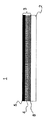
図1に示されるように、複合材料1は基体2および被覆3を備える。被覆3は、基体2に面する第1の領域31および基体2から離れて面する第2の領域32を有する。被覆3は、保護膜として障壁層4および不活性化層5を備える。障壁層は、図1の表示で基体2より下の領域に相当する基体2の周囲と、本発明の複合材料で作製された容器内に保たれる物質などの複合材料1に接している媒体の間での物質の交換を抑制する。図1では、この媒体が、不活性化層5の上に、不活性化層に接して存在する。不活性化層5は、この媒体によって腐食に対して障壁層4を保護する。
As shown in FIG. 1, the
本発明の別の実施形態によれば、被覆3は、基体2上への被覆の付着を改善するために、障壁層4および不活性化層5に加えて接着層すなわち接着促進層8を備えてよい。そのような接着層が図2に示されている。そのような複合材料は、特に容器の内部被覆に適している。
According to another embodiment of the invention, the
そのような容器6が図3に示されている。容器6は、内部空間15を囲みかつ開口部12を有する中空体10を備える。例えば飲料である媒体は、内部空間15に充填されてよく、そこから除去されてもよい。内部空間15は、不活性化層5によって障壁層4から分離される。層系の付着の改善のために、接着層または粘着層の8が障壁層4と基体の間に配置される。
Such a
図1から図3に示された実施形態に対して、SIMSによって対応する被覆が分析された。そのうえ、ATR測定が行われた。層を形成するとき、不活性化層用に前駆物質HMDSOが使用され、障壁層用に前駆物質ヘキサメチルジシラゼン(HMDSN)が使用された。不活性化層については、気体組成中の前駆物質濃度は17%から45%、73%へと100%まで変えられた。HMDSNについては、1.2%から45%へと100%まで変えられた。 For the embodiment shown in FIGS. 1-3, the corresponding coatings were analyzed by SIMS. In addition, ATR measurements were made. When forming the layer, the precursor HMDSO was used for the passivation layer and the precursor hexamethyldisilazene (HMDSN) was used for the barrier layer. For the passivation layer, the precursor concentration in the gas composition was changed from 17% to 45%, 73% to 100%. For HMDSN, it was changed from 1.2% to 45% to 100%.
製造中の前駆物質濃度の変化に対する不活性化層のATRスペクトルが図4に示されている。ある種の接着材タイプは、固有の波数で検出され得る。図5には、被覆のための気体組成中の前駆物質として45%のHMDSOで形成された1種類の不活性化層のATRスペクトルが示されている。ATR測定から、有機的な部分に関する特性数および層の内部のインタレース走査が、840cm−1、799cm−1、1253cm−1、1000cm−1および1100cm−1の波数における強度値から始まるOパラメータおよびNパラメータとして求められた。結果は表1にまとめられている。 The ATR spectrum of the passivation layer versus the change in precursor concentration during manufacture is shown in FIG. Certain adhesive types can be detected at unique wave numbers. FIG. 5 shows an ATR spectrum of one type of passivation layer formed with 45% HMDSO as a precursor in the gas composition for coating. From ATR measurement, interlaced scanning of the interior of the characteristic number and the layer an organic partial is, 840cm -1, 799cm -1, 1253cm -1, O parameters and starting from intensity values in wavenumber of 1000 cm -1 and 1100 cm -1 Obtained as N parameter. The results are summarized in Table 1.
実験中、前駆物質濃度は、低い値から100%まで増加方向に変化された。どの前駆物質濃度値がNパラメータおよびOパラメータに対して最適の結果をもたらすかについては、各場合にそれぞれ使用されるPICVD装置次第である。したがって、装置を変えるときには適切な最適化を実行しなければならない。手元の環境では、HMDSO濃度は、17%から45%、73%へと100%まで増加され、HMDSN濃度は、1.2%から45%へと100%まで増加された。 During the experiment, the precursor concentration was changed in an increasing direction from a low value to 100%. It depends on the PICVD equipment used in each case as to which precursor concentration value gives the optimum result for the N and O parameters. Therefore, appropriate optimization must be performed when changing devices. In the environment at hand, the HMDSO concentration was increased from 17% to 45%, 73% to 100%, and the HMDSN concentration was increased from 1.2% to 45% to 100%.
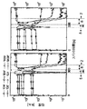
図6に、本発明による複合材料のSIMS強度のスパッタ時間特性が示されている。図6の左側に示された図は、45%のHMDSOの前駆物質濃度で形成された不活性化層5を有する複合材料で測定されたものであり、これが1.2%のHMDSNの前駆物質濃度で堆積された障壁層4をもたらし、かつPET基体2上に17%のHMDSOの前駆物質濃度で形成された接着層8をもたらす。不活性化層を形成するとき、複合材料用の前駆物質濃度は73%のHMDSOであって、そのSIMSスパッタ時間特性が図6の右側の図に示されている。残りのパラメータは不変である。
FIG. 6 shows the sputtering time characteristics of the SIMS intensity of the composite material according to the present invention. The diagram shown on the left side of FIG. 6 is measured with a composite material having a
そのようなSIMS分析の解釈により、表2にまとめられた強度比がもたらされた。前駆物質濃度の変化に関して、表1の文脈において述べたことも当てはまる。 Such interpretation of SIMS analysis resulted in the intensity ratios summarized in Table 2. The statements made in the context of Table 1 regarding the change in precursor concentration also apply.
C3に対してSIMSによって測定された信号の強度とSiに対してSIMSによって測定された信号の強度の比は、「C3/Si」の形の規格値によって示される。HMDSO濃度およびHMDSN濃度は、それぞれ、体積−%で被覆気体の濃度を示し、残りは酸素であって、分析された層を形成するときこの濃度が使用された。 Intensity ratio of C of the signals measured by SIMS for three strength and signal measured by SIMS against Si is indicated by the standard value in the form of "C 3 / Si". The HMDSO concentration and HMDSN concentration each indicated the concentration of the coating gas in volume-% and the rest was oxygen, which was used when forming the analyzed layer.
HMDSO濃度およびHMDSN濃度の増加に伴って、SIMSのC3/Si比およびATR分析からのOパラメータによって示されたように層の有機的特性が増加する。MCs+ディープ・プロファイル分析に基づき、様々な前駆物質濃度を使用してPICVD法でPET上に堆積されたSixOzCy層の組成の特性分析が行われた。 With increasing HMDSO and HMDSN concentrations, the organic properties of the layer increase as indicated by SIMS C 3 / Si ratio and O parameters from ATR analysis. Based on MCs + deep profile analysis, characterization of the composition of Si x O z C y layers deposited on PET by PICVD using various precursor concentrations was performed.
分析するのに、マトリクス状プローブの分析からの比感度係数が有効であった。層の組成を定量的に求めるために、5キロ電子ボルト(層からの信号のみ)の刺激エネルギーでWDX分析(WDX=波長分散X線分光計測)が行われた。方法論的な理由で測定することができない水素含有量を無視して、C−Astimax(登録商標)標準(100%のC)およびHerasil(ヘレウス社製の「光学用石英ガラス」)(=100%のSiO2)が分析に使用された。これに関する結果が図7(上部の表示)に示されている。 The specific sensitivity coefficient from the analysis of the matrix probe was effective for analysis. In order to quantitatively determine the composition of the layer, WDX analysis (WDX = wavelength dispersive X-ray spectroscopic measurement) was performed with a stimulation energy of 5 kV (only the signal from the layer). Ignoring the hydrogen content that cannot be measured for methodological reasons, C-Astimax® standard (100% C) and Herasil (“Optical quartz glass” from Heraeus) (= 100% SiO 2 ) was used for the analysis. The results for this are shown in FIG. 7 (upper display).
定量的なWDX分析またはEDX分析(EDX=エネルギー分散性X線回折)は、使用される方法のために数百nmの最小厚さを有する層に限定されている。SIMSの半定量的MCs+代案は、より薄い層に適している。図7では、対応する深さプロファイリングからの強度比CsC+/CsSi+およびCs2O+/CsSi+が、濃度比(WDX分析からのもの)に対して示されている。 Quantitative WDX analysis or EDX analysis (EDX = energy dispersive X-ray diffraction) is limited to layers having a minimum thickness of several hundred nm due to the method used. The SIMS semi-quantitative MCs + alternative is suitable for thinner layers. In FIG. 7, the intensity ratios CsC + / CsSi + and Cs 2 O + / CsSi + from the corresponding depth profiling are shown against the concentration ratio (from WDX analysis).
CsC+/CsSi+すなわちSiOxCy層に線形の従属性が生じ、比感度係数が求められ得て、C/Si部分の定量化が可能になる。しかし、O/Si部分を求めるときは、組成上のMCs+強度の非線形の従属性を考慮に入れなければならない(図7参照)。 A linear dependency occurs in the CsC + / CsSi +, that is, SiO x C y layer, a specific sensitivity coefficient can be obtained, and the C / Si portion can be quantified. However, when determining the O / Si portion, the compositional MCs + intensity nonlinear dependence must be taken into account (see FIG. 7).
表3では、略記「Int」は強度を表し、「Int CsC/CSi」は、CsCの信号とCSiの信号の強度比を表す。したがって「Int Cs2O/CsSi」は、Cs2Oの信号とCsSiの信号の強度比を表す。HMDSO濃度は、被覆気体中の濃度を示し、分析された不活性化層を形成するとき、この濃度が使用された。残りは酸素である。前駆物質の濃度を変える場合、表1の文脈において前述のことが当てはまる。 In Table 3, the abbreviation “Int” represents intensity, and “Int CsC / CSi” represents the intensity ratio between the CsC signal and the CSi signal. Therefore, “Int Cs 2 O / CsSi” represents the intensity ratio between the Cs 2 O signal and the CsSi signal. The HMDSO concentration indicates the concentration in the coating gas, and this concentration was used when forming the analyzed passivation layer. The rest is oxygen. When changing the concentration of the precursor, the above applies in the context of Table 1.
上記で説明された不活性化層を有する複合材料の形成の詳細が、図8から図10に示されている。障壁層4を有する基体2が調整チャンバ20内に与えられる。これは基板ホルダ23上に基体2を保持することにより図に示されている。調整チャンバは、真空ポンプ(図示せず)によって真空化されている。被覆する気体は、気体ランス22によって調整チャンバ内へ導かれる。そこで、プラズマ源25によってプラズマが点火される。本発明によってこれを行うとき、微粒子50が障壁層4の面上に堆積されて不活性化層5を形成する(図8参照)。
Details of the formation of the composite material having the passivation layer described above are shown in FIGS. A
図9に示される別の実施形態の方法では、アースされた調整チャンバ20と気体ランス22の間に無線周波数バイアスすなわちHFバイアス9が与えられる。被覆する気体51に、希ガスイオンなどの重イオンが混合される。
In another embodiment method shown in FIG. 9, a radio frequency bias or
イオンは、プラズマと容器20の間の電界の端部層内で加速され、出現する複合材料の面上および被覆に、それぞれ高エネルギーで衝突する。イオンのエネルギーが十分であると、これが被覆の圧縮および「ピンホール」のような構造の障害の減少につながる。これを行うとき、HFバイアスのエネルギーは、被覆の過熱および/または被覆からのスパッタリングさえ起こることのないように選択される。
The ions are accelerated in the end layer of the electric field between the plasma and the
プラスチック基体上の被覆の改善された付着は、この方法の特別の利点である。その上、マイクロ波刺激と比較してより高いプラズマ端部層電圧を生成する周波数が、調整チャンバ内でプラズマを生成するための励振周波数として使用されてよい。 The improved deposition of the coating on the plastic substrate is a particular advantage of this method. Moreover, the frequency that produces a higher plasma end layer voltage compared to microwave stimulation may be used as the excitation frequency for generating plasma in the conditioning chamber.
図10に示される別の実施形態の方法によれば、基体と気体ランスの間にHFバイアスが与えられてもよい。それによって、基体保持具23は基体に対して絶縁される。次いで、不活性化層の被覆が起こる領域に電界が集中され、その結果、層を形成する微粒子および混合された重イオンの堆積が特に効果的になる。
According to another embodiment method shown in FIG. 10, an HF bias may be applied between the substrate and the gas lance. Thereby, the
本発明が前述の実施形態に限定されることなく、様々なやり方で変更され得ることが当業者には明白である。特に、個々の実施形態の特徴を互いに組み合わせることもできる。明らかに、本明細書を解読し理解すると直ちに、本明細書の変更形態および改変が他者に想起されるであろう。それらが添付の特許請求の範囲またはその等価物の範囲にある限りにおいて、そのような変更形態および改変をすべて含むように意図されている。 It will be apparent to those skilled in the art that the present invention is not limited to the above-described embodiments and may be modified in various ways. In particular, the features of the individual embodiments can also be combined with one another. Obviously, variations and modifications of this specification will occur to others upon reading and understanding this specification. It is intended to embrace all such changes and modifications as long as they fall within the scope of the appended claims or their equivalents.
1 複合材料
2 基体
3 被覆
31 被覆の第1の領域
32 被覆の第2の領域
4 バリヤー層
5 不活性化層
50 PICVD被覆として堆積される微粒子
51 重イオンを含み、PICVD被覆として堆積される微粒子
6 容器
8 接着促進層
9 HFバイアスの電圧源
10 中空体
15 中空体の内部スペース
20 調整チャンバまたは処理室
22 気体ランス
23 調整チャンバ内の基体保持具
25 プラズマ源
DESCRIPTION OF
Claims (9)
b)前記障壁層を有する前記基体を調整チャンバ内へ移す工程と、
c)前記調整チャンバを真空にする工程と、
d)前記調整チャンバ内へ前駆物質および酸素を含む気体組成を導入する工程と、
e)前記気体組成と前記障壁層の間にインパルス高電圧を確立する工程と、
f)前記障壁層に隣接し、不活性化層を形成する物質の堆積で前記障壁層を被覆するプラズマを形成する工程であって、前記不活性化層はSi x O z C y を含み、x、y、およびzの和が100であり、前記xの値が15から30の範囲にあり、前記yの値が10から65の範囲にあり、かつ前記zの値が10から55の範囲にある、工程とを含み、
前記気体組成が、前記不活性化層を形成する前記前駆物質に加えられる希ガスイオンを含み、
前記不活性化層が、前記基体から離れて面するその領域内の前記障壁層の構造体を圧縮することによって形成され、
前記不活性化層を形成するとき、前記プラズマを励起するためにHFの範囲の周波数が使用され、
さらに、
g)前記気体組成を導入するための気体ランスを設ける工程を含み、
工程e)において、前記気体組成と前記障壁層の間の前記インパルス高電圧が、前記調整チャンバをアースして前記気体ランスをインパルス高電圧に接続することにより生成される、または
工程e)において、前記気体組成と前記障壁層の間の前記インパルス高電圧が、前記気体ランスと前記基体の間に高電圧インパルス源を接続することにより生成される、
複合材料を作製するための方法。 a) providing a substrate having a barrier layer;
b) transferring the substrate having the barrier layer into a conditioning chamber;
c) evacuating the conditioning chamber;
d) introducing a gas composition comprising a precursor and oxygen into the conditioning chamber;
e) establishing an impulse high voltage between the gas composition and the barrier layer;
f) adjacent to the barrier layer, comprising the steps of forming a plasma for coating the barrier layer with deposition of the material forming the passivation layer, the passivation layer comprises Si x O z C y, the sum of x, y, and z is 100, the value of x is in the range of 15 to 30, the value of y is in the range of 10 to 65, and the value of z is in the range of 10 to 55 Including the process of
The gas composition comprises noble gas ions added to the precursor forming the passivation layer ;
The passivation layer is formed by compressing the structure of the barrier layer in that region facing away from the substrate ;
When forming the front Symbol passivation layer, frequencies in the range of HF are used to excite the plasma,
further,
g) providing a gas lance for introducing the gas composition;
In step e), the impulse high voltage between the gas composition and the barrier layer is generated by grounding the conditioning chamber and connecting the gas lance to the impulse high voltage, or
In step e), the impulse high voltage between the barrier layer and the gas composition, Ru is generated by connecting a high voltage impulse sources between the gas lance and the substrate,
Method person for making a composite material.
前記複合材料は、
基体と、
前記基体上の被覆とを備え、
前記被覆が、
前記基体に面する少なくとも1つの第1の領域、前記基体から離れて面する少なくとも1つの第2の領域を備え、
前記第2の領域は、不活性化層を形成するときに障壁層の構造体を圧縮しない作製方法に比べて、ピンホールのような構造の障害を減少するように、前記基体から離れて面するその領域内の前記障壁層の構造体を圧縮することによって形成される不活性化層を備え、
前記不活性化層がSixOzCyを含み、x、y、およびzの和が100であり、前記xの値が15から30の範囲にあり、前記yの値が10から65の範囲にあり、かつ前記zの値が10から55の範囲にあり、
前記不活性化層が、ATR(減衰全反射法)で計測されたOパラメータを示し、
The composite material is
A substrate;
A coating on the substrate,
The coating is
Comprising at least one first region facing the substrate, at least one second region facing away from the substrate;
The second region is a surface away from the substrate so as to reduce structural obstacles such as pinholes compared to fabrication methods that do not compress the barrier layer structure when forming the passivation layer. Comprising a passivation layer formed by compressing the structure of the barrier layer in that region ;
The passivation layer includes Si x O z C y , the sum of x, y, and z is 100, the value of x is in the range of 15 to 30, and the value of y is 10 to 65 And the value of z is in the range of 10 to 55,
The passivation layer exhibits O parameters measured by ATR (Attenuated Total Reflection);
前記基体が、PE、PP、PET、PEN、LDPE、HDPE、PC、COC/COPおよびPLAから成る群から選択された少なくとも1つの材料、または
前記基体が、紙および少なくとも1つの複合材料から成る群から選択された少なくとも1つの材料を含む請求項3に記載の複合材料。 A plastic material selected from the group consisting of at least one polyester material, at least one polyolefin material and at least one temperature-sensitive compostable material;
The substrate is at least one material selected from the group consisting of PE, PP, PET, PEN, LDPE, HDPE, PC, COC / COP and PLA, or the substrate is made of paper and at least one composite material The composite material according to claim 3 , comprising at least one material selected from:
請求項3に記載の複合材料を備える、容器。 A container having a container wall surrounding an internal space, the container wall comprising:
A container comprising the composite material according to claim 3 .
Applications Claiming Priority (2)
| Application Number | Priority Date | Filing Date | Title |
|---|---|---|---|
| DE200610048658 DE102006048658B4 (en) | 2006-10-14 | 2006-10-14 | PICVD coating for plastic containers and process for their manufacture |
| DE102006048658.7 | 2006-10-14 |
Publications (3)
| Publication Number | Publication Date |
|---|---|
| JP2008132766A JP2008132766A (en) | 2008-06-12 |
| JP2008132766A5 JP2008132766A5 (en) | 2010-11-25 |
| JP5583885B2 true JP5583885B2 (en) | 2014-09-03 |
Family
ID=38819632
Family Applications (2)
| Application Number | Title | Priority Date | Filing Date |
|---|---|---|---|
| JP2009531716A Pending JP2010507015A (en) | 2006-10-14 | 2007-08-30 | PICVD coating for plastic containers |
| JP2007266779A Active JP5583885B2 (en) | 2006-10-14 | 2007-10-12 | PICVD coating for plastic containers |
Family Applications Before (1)
| Application Number | Title | Priority Date | Filing Date |
|---|---|---|---|
| JP2009531716A Pending JP2010507015A (en) | 2006-10-14 | 2007-08-30 | PICVD coating for plastic containers |
Country Status (7)
| Country | Link |
|---|---|
| US (1) | US8067070B2 (en) |
| EP (2) | EP2079783B1 (en) |
| JP (2) | JP2010507015A (en) |
| CN (1) | CN101522766B (en) |
| AT (1) | ATE465206T1 (en) |
| DE (2) | DE102006048658B4 (en) |
| WO (1) | WO2008043325A1 (en) |
Families Citing this family (52)
| Publication number | Priority date | Publication date | Assignee | Title |
|---|---|---|---|---|
| DE102007022748B4 (en) * | 2007-05-15 | 2009-03-05 | Qimonda Ag | Method for structuring a material and structured material |
| KR101470020B1 (en) * | 2008-03-18 | 2014-12-10 | 엘지이노텍 주식회사 | epitaxial semiconductor thin-film transfer using sandwich-structured wafer bonding and photon-beam |
| JP5159422B2 (en) * | 2008-05-15 | 2013-03-06 | 北海製罐株式会社 | Polyester resin container |
| DE102008058034B4 (en) | 2008-11-18 | 2014-05-15 | Imp Pape Gmbh & Co. Kg | Use of a syringe as a storage container for ready-to-use pharmaceutical preparations and syringe set |
| US7985188B2 (en) | 2009-05-13 | 2011-07-26 | Cv Holdings Llc | Vessel, coating, inspection and processing apparatus |
| MX350703B (en) | 2009-05-13 | 2017-09-14 | Sio2 Medical Products Inc | Outgassing method for inspecting a coated surface. |
| WO2013170052A1 (en) | 2012-05-09 | 2013-11-14 | Sio2 Medical Products, Inc. | Saccharide protective coating for pharmaceutical package |
| US9458536B2 (en) | 2009-07-02 | 2016-10-04 | Sio2 Medical Products, Inc. | PECVD coating methods for capped syringes, cartridges and other articles |
| US11624115B2 (en) | 2010-05-12 | 2023-04-11 | Sio2 Medical Products, Inc. | Syringe with PECVD lubrication |
| US9878101B2 (en) * | 2010-11-12 | 2018-01-30 | Sio2 Medical Products, Inc. | Cyclic olefin polymer vessels and vessel coating methods |
| DE102010055155A1 (en) * | 2010-12-15 | 2012-06-21 | Khs Corpoplast Gmbh | Method for plasma treatment of workpieces and workpiece with gas barrier layer |
| US9272095B2 (en) | 2011-04-01 | 2016-03-01 | Sio2 Medical Products, Inc. | Vessels, contact surfaces, and coating and inspection apparatus and methods |
| DE102011104730A1 (en) * | 2011-06-16 | 2012-12-20 | Khs Corpoplast Gmbh | Method for plasma treatment of workpieces and workpiece with gas barrier layer |
| US11116695B2 (en) | 2011-11-11 | 2021-09-14 | Sio2 Medical Products, Inc. | Blood sample collection tube |
| EP2776603B1 (en) | 2011-11-11 | 2019-03-06 | SiO2 Medical Products, Inc. | PASSIVATION, pH PROTECTIVE OR LUBRICITY COATING FOR PHARMACEUTICAL PACKAGE, COATING PROCESS AND APPARATUS |
| US20150297800A1 (en) | 2012-07-03 | 2015-10-22 | Sio2 Medical Products, Inc. | SiOx BARRIER FOR PHARMACEUTICAL PACKAGE AND COATING PROCESS |
| CN106170582A (en) * | 2012-07-03 | 2016-11-30 | Sio2医药产品公司 | SiOx barriers and coating methods for pharmaceutical packaging |
| CA2890066C (en) | 2012-11-01 | 2021-11-09 | Sio2 Medical Products, Inc. | Coating inspection method |
| US9903782B2 (en) | 2012-11-16 | 2018-02-27 | Sio2 Medical Products, Inc. | Method and apparatus for detecting rapid barrier coating integrity characteristics |
| JP6382830B2 (en) | 2012-11-30 | 2018-08-29 | エスアイオーツー・メディカル・プロダクツ・インコーポレイテッド | Uniformity control of PECVD deposition on medical syringes, cartridges, etc. |
| US9764093B2 (en) | 2012-11-30 | 2017-09-19 | Sio2 Medical Products, Inc. | Controlling the uniformity of PECVD deposition |
| US9662450B2 (en) | 2013-03-01 | 2017-05-30 | Sio2 Medical Products, Inc. | Plasma or CVD pre-treatment for lubricated pharmaceutical package, coating process and apparatus |
| EP2971228B1 (en) | 2013-03-11 | 2023-06-21 | Si02 Medical Products, Inc. | Coated packaging |
| US9937099B2 (en) | 2013-03-11 | 2018-04-10 | Sio2 Medical Products, Inc. | Trilayer coated pharmaceutical packaging with low oxygen transmission rate |
| US20160017490A1 (en) | 2013-03-15 | 2016-01-21 | Sio2 Medical Products, Inc. | Coating method |
| WO2015038850A2 (en) | 2013-09-12 | 2015-03-19 | Sio2 Medical Products, Inc. | Rapid, non-destructive, selective infrared spectrometry analysis of organic coatings on molded articles |
| WO2015148471A1 (en) | 2014-03-28 | 2015-10-01 | Sio2 Medical Products, Inc. | Antistatic coatings for plastic vessels |
| US9725802B2 (en) | 2014-11-11 | 2017-08-08 | Graham Packaging Company, L.P. | Method for making pet containers with enhanced silicon dioxide barrier coating |
| CN104760460A (en) * | 2015-03-31 | 2015-07-08 | 苏州禾盛新型材料股份有限公司 | Single-side embossed PCM steel plate |
| WO2017005621A1 (en) * | 2015-07-07 | 2017-01-12 | Agc Glass Europe | Glass substrate with increased weathering and chemcial resistance |
| EP3337915B1 (en) | 2015-08-18 | 2021-11-03 | SiO2 Medical Products, Inc. | Pharmaceutical and other packaging with low oxygen transmission rate |
| JP6850727B2 (en) * | 2015-09-29 | 2021-03-31 | 日精エー・エス・ビー機械株式会社 | Bottles, coating films, and manufacturing methods |
| EP3377100B1 (en) | 2015-11-18 | 2025-02-26 | Formycon AG | Pre-filled pharmaceutical package comprising a liquid formulation of a vegf-antagonist |
| WO2018218013A2 (en) | 2017-05-24 | 2018-11-29 | Sio2 Medical Products, Inc. | Sterilizable pharmaceutical package for ophthalmic formulations |
| CA3005132A1 (en) | 2015-11-18 | 2017-05-26 | Sio2 Medical Products, Inc. | Coated syringe for ophthalmic formulations containing a vegf antagonist |
| USD977142S1 (en) | 2016-08-18 | 2023-01-31 | Sio2 Medical Products, Inc. | Vial |
| EP3630043A1 (en) | 2017-05-24 | 2020-04-08 | Formycon AG | Sterilizable pre-filled pharmaceutical packages comprising a liquid formulation of a vegf-antagonist |
| WO2019191269A1 (en) | 2018-03-27 | 2019-10-03 | Sio2 Medical Products, Inc. | Vessels, containers, and surfaces coated with water barrier coatings |
| EP3873569A1 (en) | 2018-10-29 | 2021-09-08 | SiO2 Medical Products, Inc. | Primary containers with improved protein drug stability and lower immune response |
| CA3125944A1 (en) | 2019-01-07 | 2020-07-16 | Sio2 Medical Products, Inc. | Polymer process bags and methods for manufacturing the same |
| DE102019107660A1 (en) * | 2019-03-26 | 2020-10-01 | Krones Ag | Method and device for coating containers |
| EP3947182A1 (en) | 2019-04-05 | 2022-02-09 | SiO2 Medical Products, Inc. | Biodegradable and compostable vessels, such as coffee pods, coated with pecvd coatings or layers |
| US20240375106A1 (en) | 2019-10-11 | 2024-11-14 | Sio2 Medical Products, Inc. | Blood sample collection tube and uses thereof |
| USD948743S1 (en) | 2019-11-06 | 2022-04-12 | Sio2 Medical Products, Inc. | Collection tube assembly |
| USD962466S1 (en) | 2019-11-06 | 2022-08-30 | Sio2 Medical Products, Inc. | Collection tube assembly |
| US20230242323A1 (en) | 2020-06-16 | 2023-08-03 | Sio2 Medical Products, Inc. | Packages comprising anti-microbial coatings for preventing contamination, e.g. after first use of the product |
| CA3184061A1 (en) | 2020-06-22 | 2021-12-30 | Ahmad TAHA | Atomic layer deposition coated pharmaceutical packaging and improved syringes and vials, e.g. for lyophilized/cold-chain drugs/vaccines |
| EP4188996A1 (en) | 2020-07-28 | 2023-06-07 | SiO2 Medical Products, Inc. | Method and package for reducing the degradation of a drug and/or excipient, e.g. polysorbate stabilizer, in a pharmaceutical product |
| EP4197021A2 (en) | 2020-08-12 | 2023-06-21 | SiO2 Medical Products, Inc. | Pulsed plasma enhanced chemical vapor deposition process and system |
| JP2024513061A (en) | 2021-03-31 | 2024-03-21 | エスアイオーツー・メディカル・プロダクツ・インコーポレイテッド | Atomic layer deposition coated pharmaceutical packaging and improved syringes and vials for e.g. freeze-dried/cold chain drugs/vaccines |
| MX2024000721A (en) * | 2021-07-16 | 2024-03-25 | Cg Biocomposite Aps | Biodegradable composite articles. |
| DE102022105041A1 (en) | 2022-03-03 | 2023-09-07 | IonKraft GmbH | Coating technology for plastic containers |
Family Cites Families (21)
| Publication number | Priority date | Publication date | Assignee | Title |
|---|---|---|---|---|
| US5041303A (en) * | 1988-03-07 | 1991-08-20 | Polyplasma Incorporated | Process for modifying large polymeric surfaces |
| DE4438359C2 (en) * | 1994-10-27 | 2001-10-04 | Schott Glas | Plastic container with a barrier coating |
| WO1996033098A2 (en) * | 1995-04-13 | 1996-10-24 | Xmx Corporation | Gas-impermeable, chemically inert container structure and method of producingthe same |
| DE19650286C2 (en) * | 1996-02-28 | 2002-07-11 | Fraunhofer Ges Forschung | packing material |
| DE19801320B4 (en) * | 1998-01-16 | 2004-08-26 | Schott Glas | Filled and sealed plastic container and process for its manufacture |
| JP2000127290A (en) * | 1998-09-30 | 2000-05-09 | Becton Dickinson & Co | Barrier coating and method for depositing barrier coating on plastic objects by high power plasma enhanced chemical vapor deposition |
| US6720052B1 (en) * | 2000-08-24 | 2004-04-13 | The Coca-Cola Company | Multilayer polymeric/inorganic oxide structure with top coat for enhanced gas or vapor barrier and method for making same |
| JP2002161247A (en) * | 2000-11-28 | 2002-06-04 | Nippon Shokubai Co Ltd | Coating film for gas barrier having excellent boiling resistance |
| TW570876B (en) * | 2001-05-11 | 2004-01-11 | Toyo Seikan Kaisha Ltd | Silicon oxide film |
| JP3678361B2 (en) * | 2001-06-08 | 2005-08-03 | 大日本印刷株式会社 | Gas barrier film |
| JP2003098341A (en) * | 2001-09-25 | 2003-04-03 | Nidec Copal Corp | Method for manufacturing optical element for laser |
| EP1448807A4 (en) * | 2001-10-30 | 2005-07-13 | Massachusetts Inst Technology | FLUOROCARBON-ORGANOSILICIUM COPOLYMERS AND COATINGS PREPARED BY CHEMICAL VAPOR DEPOSITION BY HOT FILAMENT |
| EP1388594B1 (en) * | 2002-08-07 | 2010-01-06 | Schott Ag | Composite material with smooth barrier layer and process for its production |
| EP1630250B1 (en) * | 2003-03-28 | 2013-03-06 | Toyo Seikan Kaisha, Ltd. | Chemical vapor deposition film formed by plasma cvd process and method for forming same |
| DE10314779A1 (en) * | 2003-03-31 | 2004-10-14 | Kuraray Specialities Europe Gmbh | Medical-pharmaceutical plastic container with improved barrier effect |
| JP2005096275A (en) * | 2003-09-25 | 2005-04-14 | Dainippon Printing Co Ltd | Barrier film |
| JP4414781B2 (en) * | 2004-02-09 | 2010-02-10 | 大日本印刷株式会社 | Barrier film manufacturing method |
| DE102004017236B4 (en) * | 2004-04-05 | 2012-10-25 | Schott Ag | Composite having improved chemical resistance and method of making the same |
| JP2006192858A (en) * | 2005-01-17 | 2006-07-27 | Dainippon Printing Co Ltd | Barrier film |
| JP4747605B2 (en) * | 2005-02-22 | 2011-08-17 | 東洋製罐株式会社 | Deposition film by plasma CVD method |
| JP2006276658A (en) * | 2005-03-30 | 2006-10-12 | Matsushita Electric Ind Co Ltd | Deposition method on substrate |
-
2006
- 2006-10-14 DE DE200610048658 patent/DE102006048658B4/en active Active
-
2007
- 2007-08-30 CN CN2007800366641A patent/CN101522766B/en active Active
- 2007-08-30 JP JP2009531716A patent/JP2010507015A/en active Pending
- 2007-08-30 WO PCT/DE2007/001552 patent/WO2008043325A1/en not_active Ceased
- 2007-08-30 EP EP20070801289 patent/EP2079783B1/en active Active
- 2007-10-11 EP EP20070019903 patent/EP1911794B1/en active Active
- 2007-10-11 DE DE200750003491 patent/DE502007003491D1/en active Active
- 2007-10-11 US US11/870,941 patent/US8067070B2/en active Active
- 2007-10-11 AT AT07019903T patent/ATE465206T1/en active
- 2007-10-12 JP JP2007266779A patent/JP5583885B2/en active Active
Also Published As
| Publication number | Publication date |
|---|---|
| US20080090039A1 (en) | 2008-04-17 |
| ATE465206T1 (en) | 2010-05-15 |
| EP1911794A1 (en) | 2008-04-16 |
| JP2008132766A (en) | 2008-06-12 |
| US8067070B2 (en) | 2011-11-29 |
| WO2008043325A1 (en) | 2008-04-17 |
| JP2010507015A (en) | 2010-03-04 |
| EP2079783A1 (en) | 2009-07-22 |
| CN101522766A (en) | 2009-09-02 |
| DE102006048658B4 (en) | 2014-03-27 |
| DE102006048658A1 (en) | 2008-04-17 |
| CN101522766B (en) | 2011-12-07 |
| DE502007003491D1 (en) | 2010-06-02 |
| EP2079783B1 (en) | 2012-05-23 |
| EP1911794B1 (en) | 2010-04-21 |
Similar Documents
| Publication | Publication Date | Title |
|---|---|---|
| JP5583885B2 (en) | PICVD coating for plastic containers | |
| JP5362941B2 (en) | Composite materials with improved chemical resistance | |
| Boutroy et al. | Hydrogenated amorphous carbon film coating of PET bottles for gas diffusion barriers | |
| US10081864B2 (en) | Method and apparatus for treating containers | |
| JP4388804B2 (en) | Composite material comprising base material and barrier layer material | |
| US9302816B2 (en) | Polymer article having a thin coating formed on at least one of its sides by plasma and method for producing such an article | |
| US20040149225A1 (en) | Process and apparatus for depositing plasma coating onto a container | |
| US7906217B2 (en) | Vapor deposited film by plasma CVD method | |
| US20220169430A1 (en) | Biodegradable and compostable vessels, such as coffee pods, coated with pecvd coatings or layers | |
| JP4372833B1 (en) | Method for producing gas barrier thin film coated plastic container | |
| Gebhard et al. | A combinatorial approach to enhance barrier properties of thin films on polymers: Seeding and capping of PECVD thin films by PEALD | |
| Lee et al. | Simple realization of efficient barrier performance of a single layer silicon nitride film via plasma chemistry | |
| Jacq et al. | H atom surface loss kinetics in pulsed inductively coupled plasmas | |
| Besch et al. | Allylamine plasma polymer coatings of interior surfaces in small trench structures | |
| JP2003328131A (en) | Silicon oxide film with excellent gas barrier property, and packaging body | |
| JP3979031B2 (en) | Silicon oxide coating | |
| JP3864126B2 (en) | Inner coated polyester resin container | |
| DK1893788T3 (en) | POLYMER ARTICLE WITH A THIN COATING MADE ON AT LEAST ITS PLASMA SIDE | |
| JP2017007683A (en) | Plastic container and film forming method and device of the same |
Legal Events
| Date | Code | Title | Description |
|---|---|---|---|
| A521 | Request for written amendment filed |
Free format text: JAPANESE INTERMEDIATE CODE: A523 Effective date: 20101012 |
|
| A621 | Written request for application examination |
Free format text: JAPANESE INTERMEDIATE CODE: A621 Effective date: 20101012 |
|
| A977 | Report on retrieval |
Free format text: JAPANESE INTERMEDIATE CODE: A971007 Effective date: 20120521 |
|
| A131 | Notification of reasons for refusal |
Free format text: JAPANESE INTERMEDIATE CODE: A131 Effective date: 20120528 |
|
| A601 | Written request for extension of time |
Free format text: JAPANESE INTERMEDIATE CODE: A601 Effective date: 20120828 |
|
| A602 | Written permission of extension of time |
Free format text: JAPANESE INTERMEDIATE CODE: A602 Effective date: 20120831 |
|
| A521 | Request for written amendment filed |
Free format text: JAPANESE INTERMEDIATE CODE: A523 Effective date: 20121128 |
|
| A131 | Notification of reasons for refusal |
Free format text: JAPANESE INTERMEDIATE CODE: A131 Effective date: 20130711 |
|
| A601 | Written request for extension of time |
Free format text: JAPANESE INTERMEDIATE CODE: A601 Effective date: 20131011 |
|
| A602 | Written permission of extension of time |
Free format text: JAPANESE INTERMEDIATE CODE: A602 Effective date: 20131017 |
|
| A601 | Written request for extension of time |
Free format text: JAPANESE INTERMEDIATE CODE: A601 Effective date: 20131211 |
|
| A602 | Written permission of extension of time |
Free format text: JAPANESE INTERMEDIATE CODE: A602 Effective date: 20131216 |
|
| A521 | Request for written amendment filed |
Free format text: JAPANESE INTERMEDIATE CODE: A523 Effective date: 20140114 |
|
| RD04 | Notification of resignation of power of attorney |
Free format text: JAPANESE INTERMEDIATE CODE: A7424 Effective date: 20140227 |
|
| TRDD | Decision of grant or rejection written | ||
| A01 | Written decision to grant a patent or to grant a registration (utility model) |
Free format text: JAPANESE INTERMEDIATE CODE: A01 Effective date: 20140619 |
|
| A61 | First payment of annual fees (during grant procedure) |
Free format text: JAPANESE INTERMEDIATE CODE: A61 Effective date: 20140717 |
|
| R150 | Certificate of patent or registration of utility model |
Ref document number: 5583885 Country of ref document: JP Free format text: JAPANESE INTERMEDIATE CODE: R150 |
|
| R250 | Receipt of annual fees |
Free format text: JAPANESE INTERMEDIATE CODE: R250 |
|
| R250 | Receipt of annual fees |
Free format text: JAPANESE INTERMEDIATE CODE: R250 |
|
| R250 | Receipt of annual fees |
Free format text: JAPANESE INTERMEDIATE CODE: R250 |
|
| R250 | Receipt of annual fees |
Free format text: JAPANESE INTERMEDIATE CODE: R250 |
|
| R250 | Receipt of annual fees |
Free format text: JAPANESE INTERMEDIATE CODE: R250 |
|
| R250 | Receipt of annual fees |
Free format text: JAPANESE INTERMEDIATE CODE: R250 |
|
| R250 | Receipt of annual fees |
Free format text: JAPANESE INTERMEDIATE CODE: R250 |
|
| R250 | Receipt of annual fees |
Free format text: JAPANESE INTERMEDIATE CODE: R250 |
|
| R250 | Receipt of annual fees |
Free format text: JAPANESE INTERMEDIATE CODE: R250 |