JP5701802B2 - 電力用半導体装置 - Google Patents
電力用半導体装置 Download PDFInfo
- Publication number
- JP5701802B2 JP5701802B2 JP2012066956A JP2012066956A JP5701802B2 JP 5701802 B2 JP5701802 B2 JP 5701802B2 JP 2012066956 A JP2012066956 A JP 2012066956A JP 2012066956 A JP2012066956 A JP 2012066956A JP 5701802 B2 JP5701802 B2 JP 5701802B2
- Authority
- JP
- Japan
- Prior art keywords
- semiconductor substrate
- electrode
- layer
- pillar
- insulating film
- Prior art date
- Legal status (The legal status is an assumption and is not a legal conclusion. Google has not performed a legal analysis and makes no representation as to the accuracy of the status listed.)
- Expired - Fee Related
Links
Images


Classifications
-
- H—ELECTRICITY
- H10—SEMICONDUCTOR DEVICES; ELECTRIC SOLID-STATE DEVICES NOT OTHERWISE PROVIDED FOR
- H10D—INORGANIC ELECTRIC SEMICONDUCTOR DEVICES
- H10D64/00—Electrodes of devices having potential barriers
- H10D64/111—Field plates
- H10D64/117—Recessed field plates, e.g. trench field plates or buried field plates
-
- H—ELECTRICITY
- H10—SEMICONDUCTOR DEVICES; ELECTRIC SOLID-STATE DEVICES NOT OTHERWISE PROVIDED FOR
- H10D—INORGANIC ELECTRIC SEMICONDUCTOR DEVICES
- H10D12/00—Bipolar devices controlled by the field effect, e.g. insulated-gate bipolar transistors [IGBT]
- H10D12/411—Insulated-gate bipolar transistors [IGBT]
- H10D12/441—Vertical IGBTs
-
- H—ELECTRICITY
- H10—SEMICONDUCTOR DEVICES; ELECTRIC SOLID-STATE DEVICES NOT OTHERWISE PROVIDED FOR
- H10D—INORGANIC ELECTRIC SEMICONDUCTOR DEVICES
- H10D30/00—Field-effect transistors [FET]
- H10D30/01—Manufacture or treatment
- H10D30/021—Manufacture or treatment of FETs having insulated gates [IGFET]
- H10D30/028—Manufacture or treatment of FETs having insulated gates [IGFET] of double-diffused metal oxide semiconductor [DMOS] FETs
- H10D30/0291—Manufacture or treatment of FETs having insulated gates [IGFET] of double-diffused metal oxide semiconductor [DMOS] FETs of vertical DMOS [VDMOS] FETs
-
- H—ELECTRICITY
- H10—SEMICONDUCTOR DEVICES; ELECTRIC SOLID-STATE DEVICES NOT OTHERWISE PROVIDED FOR
- H10D—INORGANIC ELECTRIC SEMICONDUCTOR DEVICES
- H10D30/00—Field-effect transistors [FET]
- H10D30/60—Insulated-gate field-effect transistors [IGFET]
- H10D30/64—Double-diffused metal-oxide semiconductor [DMOS] FETs
- H10D30/66—Vertical DMOS [VDMOS] FETs
- H10D30/665—Vertical DMOS [VDMOS] FETs having edge termination structures
-
- H—ELECTRICITY
- H10—SEMICONDUCTOR DEVICES; ELECTRIC SOLID-STATE DEVICES NOT OTHERWISE PROVIDED FOR
- H10D—INORGANIC ELECTRIC SEMICONDUCTOR DEVICES
- H10D62/00—Semiconductor bodies, or regions thereof, of devices having potential barriers
- H10D62/01—Manufacture or treatment
- H10D62/051—Forming charge compensation regions, e.g. superjunctions
- H10D62/058—Forming charge compensation regions, e.g. superjunctions by using trenches, e.g. implanting into sidewalls of trenches or refilling trenches
-
- H—ELECTRICITY
- H10—SEMICONDUCTOR DEVICES; ELECTRIC SOLID-STATE DEVICES NOT OTHERWISE PROVIDED FOR
- H10D—INORGANIC ELECTRIC SEMICONDUCTOR DEVICES
- H10D62/00—Semiconductor bodies, or regions thereof, of devices having potential barriers
- H10D62/10—Shapes, relative sizes or dispositions of the regions of the semiconductor bodies; Shapes of the semiconductor bodies
- H10D62/102—Constructional design considerations for preventing surface leakage or controlling electric field concentration
- H10D62/103—Constructional design considerations for preventing surface leakage or controlling electric field concentration for increasing or controlling the breakdown voltage of reverse-biased devices
- H10D62/105—Constructional design considerations for preventing surface leakage or controlling electric field concentration for increasing or controlling the breakdown voltage of reverse-biased devices by having particular doping profiles, shapes or arrangements of PN junctions; by having supplementary regions, e.g. junction termination extension [JTE]
- H10D62/109—Reduced surface field [RESURF] PN junction structures
- H10D62/111—Multiple RESURF structures, e.g. double RESURF or 3D-RESURF structures
-
- H—ELECTRICITY
- H10—SEMICONDUCTOR DEVICES; ELECTRIC SOLID-STATE DEVICES NOT OTHERWISE PROVIDED FOR
- H10D—INORGANIC ELECTRIC SEMICONDUCTOR DEVICES
- H10D64/00—Electrodes of devices having potential barriers
- H10D64/111—Field plates
- H10D64/112—Field plates comprising multiple field plate segments
-
- H—ELECTRICITY
- H10—SEMICONDUCTOR DEVICES; ELECTRIC SOLID-STATE DEVICES NOT OTHERWISE PROVIDED FOR
- H10D—INORGANIC ELECTRIC SEMICONDUCTOR DEVICES
- H10D62/00—Semiconductor bodies, or regions thereof, of devices having potential barriers
- H10D62/10—Shapes, relative sizes or dispositions of the regions of the semiconductor bodies; Shapes of the semiconductor bodies
- H10D62/102—Constructional design considerations for preventing surface leakage or controlling electric field concentration
- H10D62/112—Constructional design considerations for preventing surface leakage or controlling electric field concentration for preventing surface leakage due to surface inversion layers, e.g. by using channel stoppers
-
- H—ELECTRICITY
- H10—SEMICONDUCTOR DEVICES; ELECTRIC SOLID-STATE DEVICES NOT OTHERWISE PROVIDED FOR
- H10D—INORGANIC ELECTRIC SEMICONDUCTOR DEVICES
- H10D62/00—Semiconductor bodies, or regions thereof, of devices having potential barriers
- H10D62/10—Shapes, relative sizes or dispositions of the regions of the semiconductor bodies; Shapes of the semiconductor bodies
- H10D62/124—Shapes, relative sizes or dispositions of the regions of semiconductor bodies or of junctions between the regions
- H10D62/126—Top-view geometrical layouts of the regions or the junctions
- H10D62/127—Top-view geometrical layouts of the regions or the junctions of cellular field-effect devices, e.g. multicellular DMOS transistors or IGBTs
-
- H—ELECTRICITY
- H10—SEMICONDUCTOR DEVICES; ELECTRIC SOLID-STATE DEVICES NOT OTHERWISE PROVIDED FOR
- H10D—INORGANIC ELECTRIC SEMICONDUCTOR DEVICES
- H10D62/00—Semiconductor bodies, or regions thereof, of devices having potential barriers
- H10D62/10—Shapes, relative sizes or dispositions of the regions of the semiconductor bodies; Shapes of the semiconductor bodies
- H10D62/17—Semiconductor regions connected to electrodes not carrying current to be rectified, amplified or switched, e.g. channel regions
- H10D62/393—Body regions of DMOS transistors or IGBTs
-
- H—ELECTRICITY
- H10—SEMICONDUCTOR DEVICES; ELECTRIC SOLID-STATE DEVICES NOT OTHERWISE PROVIDED FOR
- H10D—INORGANIC ELECTRIC SEMICONDUCTOR DEVICES
- H10D64/00—Electrodes of devices having potential barriers
- H10D64/111—Field plates
Landscapes
- Electrodes Of Semiconductors (AREA)
- Chemical & Material Sciences (AREA)
- Composite Materials (AREA)
Description
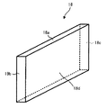
11、11´・・・半導体基板
11a・・・半導体層
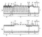
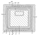
12・・・ソース電極
13・・・MOSFET素子
14・・・ゲートパッド
15・・・ゲート電極
15a・・・ゲート絶縁膜
16・・・フィールドプレート電極パッド
17・・・EQPR電極パッド
18、18´・・・pピラー層
18a、18a´・・・pピラー層の上面
18b、18b´・・・pピラー層の一端面
18c、18c´・・・pピラー層の他端面
18d、18d´・・・pピラー層の側面
19・・・nピラー層
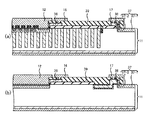
22・・・電界緩和層
23・・・第1の絶縁膜
24・・・電界緩和層
25・・・第2の絶縁膜
26・・・素子部
27・・・終端部
28・・・ベース層
29・・・コンタクト層
30・・・ベース層
31・・・コンタクト層
32・・・ソース層
33・・・高濃度半導体基板
34、34´・・・ドレイン電極
35・・・フィールド酸化膜
36、36´・・・フィールドプレート電極
37・・・チャネルストップ層
37−1・・・p型のチャネルストップ層
37−2・・・n型のチャネルストップ層
38、38´・・・EQPR電極
39・・・第3の絶縁膜
40・・・トレンチ
41・・・第1のトレンチ
42・・・第2のトレンチ
Claims (7)
- 電力用半導体素子が設けられた素子部、および前記素子部の周囲に設けられた終端部、
からなる電力用半導体装置であって、
第1導電型の半導体基板と、
前記半導体基板の上面のうち、前記素子部の一部に設けられた第2導電型の第1の不純物層と、
前記第1の不純物層にゲート絶縁膜を介して接するように設けられたゲート電極と、
前記第1の不純物層の上面の一部に設けられた第1導電型の第2の不純物層と、
前記半導体基板の下面に設けられた第1の電極と、
前記半導体基板の前記上面に、少なくとも前記第2の不純物層に接するように設けられた第2の電極と、
それぞれが、前記半導体基板の上面から露出する帯状の上面または前記第1の不純物層の下面に接する帯状の上面、前記上面を構成する短辺の一方を含み、前記上面に対して垂直な平面である一端面、前記上面を構成する短辺の他方を含み、前記上面に対して垂直な平面である他端面、および前記上面を構成する長辺のいずれか一方を含み、前記上面に対して垂直な平面である側面、を有し、前記上面から前記半導体基板の深さ方向に埋め込まれるように設けられた平面状であって、前記第2の電極の下および前記第2の電極から露出する前記終端部において、前記上面が所定の間隔でストライプ状に配列されるように設けられた複数の第2導電型のピラー層と、
前記終端部の前記半導体基板の上面に、前記複数の第2導電型のピラー層の前記上面を囲うように設けられた、前記半導体基板より高濃度である第1導電型の第3の不純物層と、
前記第3の不純物層上に設けられた、ポリシリコンからなるEQPR電極と、
前記第2の電極から露出する前記終端部の前記半導体基板であって、前記ピラー層の前記一端面を含む一端部の間の前記半導体基板、および前記ピラー層の前記他端面を含む他端部の間の前記半導体基板、にそれぞれ設けられた複数の第1のトレンチと、
それぞれの前記第1のトレンチの側面および底面に設けられた第1の絶縁膜と、
それぞれの前記第1のトレンチの内部に設けられ、前記EQPR電極に電気的に接続された第1のポリシリコンと、
前記第2の電極から露出する前記終端部の前記半導体基板に、前記ピラー層の側面に沿って設けられた第2のトレンチと、
前記第2のトレンチの側面および底面に設けられた第2の絶縁膜と、
前記第2のトレンチの内部に設けられ、前記EQPR電極に電気的に接続された第2のポリシリコンと、
を具備することを特徴とする電力用半導体装置。 - 素子部、および前記素子部の周囲に設けられた終端部、
からなる電力用半導体装置であって、
第1導電型の半導体基板と、
前記半導体基板の上面のうち、前記素子部の一部に設けられた第2導電型の第1の不純物層と、
前記第1の不純物層の上面の一部に設けられた第1導電型の第2の不純物層と、
前記第1の不純物層にゲート絶縁膜を介して接するように設けられたゲート電極と、
前記半導体基板の下面に設けられた第1の電極と、
前記半導体基板の前記上面に、前記第1の不純物層に接するように設けられた第2の電極と、
少なくとも前記素子部の前記半導体基板内に設けられた複数の第2導電型のピラー層と、
前記終端部の前記半導体基板内であり、かつ互いに隣接する前記ピラー層の間に設けられた第1の絶縁膜と、
前記半導体基板の上面に、前記複数の第2導電型のピラー層を囲うように設けられた、前記半導体基板より高濃度である第1導電型の第3の不純物層と、
前記第3の不純物層上に設けられたEQPR電極と、
前記第1の絶縁膜の内部に設けられ、前記EQPR電極に電気的に接続された第1のフローティング電極と、
を具備することを特徴とする電力用半導体装置。 - 前記EQPR電極および前記第1のフローティング電極はそれぞれ、ポリシリコンからなることを特徴とする請求項2に記載の電力用半導体装置。
- 前記終端部の前記半導体基板内に、前記ピラー層に沿って設けられた第2の絶縁膜をさらに具備することを特徴とする請求項2または3に記載の電力用半導体装置。
- 前記第2の絶縁膜は、最も外側の前記ピラー層のさらに外側の前記半導体基板内に設けられたことを特徴とする請求項4に記載の電力用半導体装置。
- 前記第2の絶縁膜の内部に設けられ、前記EQPR電極に電気的に接続された第2のフローティング電極、
をさらに具備することを特徴とする請求項4または5に記載の電力用半導体装置。 - 前記EQPR電極および前記第2のフローティング電極はそれぞれ、ポリシリコンからなることを特徴とする請求項6に記載の電力用半導体装置。
Priority Applications (4)
| Application Number | Priority Date | Filing Date | Title |
|---|---|---|---|
| JP2012066956A JP5701802B2 (ja) | 2012-03-23 | 2012-03-23 | 電力用半導体装置 |
| CN2012103186164A CN103325774A (zh) | 2012-03-23 | 2012-08-31 | 电力用半导体装置 |
| US13/610,532 US8716789B2 (en) | 2012-03-23 | 2012-09-11 | Power semiconductor device |
| US14/202,912 US9041101B2 (en) | 2012-03-23 | 2014-03-10 | Power semiconductor device |
Applications Claiming Priority (1)
| Application Number | Priority Date | Filing Date | Title |
|---|---|---|---|
| JP2012066956A JP5701802B2 (ja) | 2012-03-23 | 2012-03-23 | 電力用半導体装置 |
Publications (2)
| Publication Number | Publication Date |
|---|---|
| JP2013201167A JP2013201167A (ja) | 2013-10-03 |
| JP5701802B2 true JP5701802B2 (ja) | 2015-04-15 |
Family
ID=49194438
Family Applications (1)
| Application Number | Title | Priority Date | Filing Date |
|---|---|---|---|
| JP2012066956A Expired - Fee Related JP5701802B2 (ja) | 2012-03-23 | 2012-03-23 | 電力用半導体装置 |
Country Status (3)
| Country | Link |
|---|---|
| US (2) | US8716789B2 (ja) |
| JP (1) | JP5701802B2 (ja) |
| CN (1) | CN103325774A (ja) |
Families Citing this family (19)
| Publication number | Priority date | Publication date | Assignee | Title |
|---|---|---|---|---|
| JP2012074441A (ja) * | 2010-09-28 | 2012-04-12 | Toshiba Corp | 電力用半導体装置 |
| US9614043B2 (en) | 2012-02-09 | 2017-04-04 | Vishay-Siliconix | MOSFET termination trench |
| JP5701802B2 (ja) * | 2012-03-23 | 2015-04-15 | 株式会社東芝 | 電力用半導体装置 |
| US9842911B2 (en) | 2012-05-30 | 2017-12-12 | Vishay-Siliconix | Adaptive charge balanced edge termination |
| US9406543B2 (en) * | 2013-12-10 | 2016-08-02 | Samsung Electronics Co., Ltd. | Semiconductor power devices and methods of manufacturing the same |
| DE102014005879B4 (de) * | 2014-04-16 | 2021-12-16 | Infineon Technologies Ag | Vertikale Halbleitervorrichtung |
| US9887259B2 (en) | 2014-06-23 | 2018-02-06 | Vishay-Siliconix | Modulated super junction power MOSFET devices |
| KR102098996B1 (ko) | 2014-08-19 | 2020-04-08 | 비쉐이-실리코닉스 | 초접합 금속 산화물 반도체 전계 효과 트랜지스터 |
| JP6185440B2 (ja) * | 2014-09-16 | 2017-08-23 | 株式会社東芝 | 半導体装置 |
| JP2016171279A (ja) | 2015-03-16 | 2016-09-23 | 株式会社東芝 | 半導体装置 |
| TWI652791B (zh) * | 2015-03-27 | 2019-03-01 | 力智電子股份有限公司 | 半導體裝置 |
| JP6730078B2 (ja) | 2016-04-27 | 2020-07-29 | ローム株式会社 | 半導体装置 |
| TWI737889B (zh) * | 2018-02-05 | 2021-09-01 | 力智電子股份有限公司 | 功率半導體元件 |
| US11362209B2 (en) * | 2019-04-16 | 2022-06-14 | Semiconductor Components Industries, Llc | Gate polysilicon feed structures for trench devices |
| US11302785B2 (en) * | 2019-06-18 | 2022-04-12 | Texas Instruments Incorporated | Method for testing a high voltage transistor with a field plate |
| JP7280213B2 (ja) * | 2020-03-04 | 2023-05-23 | 株式会社東芝 | 半導体装置 |
| CN115812255A (zh) * | 2020-07-10 | 2023-03-17 | 住友电气工业株式会社 | 碳化硅半导体器件 |
| JP2023070761A (ja) * | 2021-11-10 | 2023-05-22 | ローム株式会社 | 半導体装置 |
| CN115632057A (zh) * | 2022-09-21 | 2023-01-20 | 西安电子科技大学 | 一种边缘电荷平衡的SiC超级结结构及其制备方法 |
Family Cites Families (18)
| Publication number | Priority date | Publication date | Assignee | Title |
|---|---|---|---|---|
| JP4088033B2 (ja) * | 2000-11-27 | 2008-05-21 | 株式会社東芝 | 半導体装置 |
| JP3908572B2 (ja) | 2002-03-18 | 2007-04-25 | 株式会社東芝 | 半導体素子 |
| JP4393144B2 (ja) | 2003-09-09 | 2010-01-06 | 株式会社東芝 | 電力用半導体装置 |
| JP4940546B2 (ja) | 2004-12-13 | 2012-05-30 | 株式会社デンソー | 半導体装置 |
| JP4825424B2 (ja) * | 2005-01-18 | 2011-11-30 | 株式会社東芝 | 電力用半導体装置 |
| JP2006278826A (ja) * | 2005-03-30 | 2006-10-12 | Toshiba Corp | 半導体素子及びその製造方法 |
| US7541643B2 (en) * | 2005-04-07 | 2009-06-02 | Kabushiki Kaisha Toshiba | Semiconductor device |
| US7592668B2 (en) * | 2006-03-30 | 2009-09-22 | Fairchild Semiconductor Corporation | Charge balance techniques for power devices |
| JP4980663B2 (ja) | 2006-07-03 | 2012-07-18 | ルネサスエレクトロニクス株式会社 | 半導体装置および製造方法 |
| JP5196766B2 (ja) | 2006-11-20 | 2013-05-15 | 株式会社東芝 | 半導体装置 |
| JP2007116190A (ja) | 2006-12-12 | 2007-05-10 | Toshiba Corp | 半導体素子およびその製造方法 |
| JP2008187125A (ja) * | 2007-01-31 | 2008-08-14 | Toshiba Corp | 半導体装置 |
| JP5491723B2 (ja) * | 2008-11-20 | 2014-05-14 | 株式会社東芝 | 電力用半導体装置 |
| US8071461B2 (en) * | 2008-12-04 | 2011-12-06 | Freescale Semiconductor, Inc. | Low loss substrate for integrated passive devices |
| KR20100123789A (ko) | 2009-05-16 | 2010-11-25 | 박종남 | 발효용기 |
| JP5606019B2 (ja) | 2009-07-21 | 2014-10-15 | 株式会社東芝 | 電力用半導体素子およびその製造方法 |
| JP5235960B2 (ja) * | 2010-09-10 | 2013-07-10 | 株式会社東芝 | 電力用半導体装置及びその製造方法 |
| JP5701802B2 (ja) * | 2012-03-23 | 2015-04-15 | 株式会社東芝 | 電力用半導体装置 |
-
2012
- 2012-03-23 JP JP2012066956A patent/JP5701802B2/ja not_active Expired - Fee Related
- 2012-08-31 CN CN2012103186164A patent/CN103325774A/zh active Pending
- 2012-09-11 US US13/610,532 patent/US8716789B2/en not_active Expired - Fee Related
-
2014
- 2014-03-10 US US14/202,912 patent/US9041101B2/en not_active Expired - Fee Related
Also Published As
| Publication number | Publication date |
|---|---|
| US20130248979A1 (en) | 2013-09-26 |
| US9041101B2 (en) | 2015-05-26 |
| JP2013201167A (ja) | 2013-10-03 |
| US20140191310A1 (en) | 2014-07-10 |
| US8716789B2 (en) | 2014-05-06 |
| CN103325774A (zh) | 2013-09-25 |
Similar Documents
| Publication | Publication Date | Title |
|---|---|---|
| JP5701802B2 (ja) | 電力用半導体装置 | |
| US8957502B2 (en) | Semiconductor device | |
| CN102163621B (zh) | 半导体器件以及制造半导体器件的方法 | |
| CN105280711B (zh) | 电荷补偿结构及用于其的制造 | |
| CN102403356B (zh) | 半导体装置 | |
| JP5537996B2 (ja) | 半導体装置 | |
| CN102947937A (zh) | 半导体装置及半导体装置的制造方法 | |
| JP2008182054A (ja) | 半導体装置 | |
| WO2013035818A1 (ja) | 半導体装置 | |
| JP5687582B2 (ja) | 半導体素子およびその製造方法 | |
| US9112023B2 (en) | Multi-gate VDMOS transistor and method for forming the same | |
| CN102456716A (zh) | 半导体器件 | |
| CN106711191A (zh) | 具有终端保护区的超结半导体器件及其制造方法 | |
| CN102254930A (zh) | 半导体装置及其制造方法 | |
| JP2013069852A (ja) | 半導体装置 | |
| JP2016225343A (ja) | 半導体装置 | |
| JP2009141185A (ja) | 半導体装置及びその製造方法 | |
| US10892359B2 (en) | Semiconductor device | |
| JP2013243272A (ja) | 炭化珪素半導体装置およびその製造方法 | |
| US20160079350A1 (en) | Semiconductor device and manufacturing method thereof | |
| US20110169080A1 (en) | Charge balance power device and manufacturing method thereof | |
| JP2012160601A (ja) | 半導体装置の製造方法 | |
| KR20170015342A (ko) | 복합 트렌치 및 주입 컬럼들을 가진 반도체 디바이스 | |
| CN102449770B (zh) | 用于半导体器件的3d沟道结构 | |
| KR20200105350A (ko) | 수퍼 정션 반도체 장치 및 이의 제조 방법 |
Legal Events
| Date | Code | Title | Description |
|---|---|---|---|
| A621 | Written request for application examination |
Free format text: JAPANESE INTERMEDIATE CODE: A621 Effective date: 20140131 |
|
| A977 | Report on retrieval |
Free format text: JAPANESE INTERMEDIATE CODE: A971007 Effective date: 20140523 |
|
| A131 | Notification of reasons for refusal |
Free format text: JAPANESE INTERMEDIATE CODE: A131 Effective date: 20140527 |
|
| A521 | Request for written amendment filed |
Free format text: JAPANESE INTERMEDIATE CODE: A523 Effective date: 20140609 |
|
| A131 | Notification of reasons for refusal |
Free format text: JAPANESE INTERMEDIATE CODE: A131 Effective date: 20141028 |
|
| A521 | Request for written amendment filed |
Free format text: JAPANESE INTERMEDIATE CODE: A523 Effective date: 20141225 |
|
| TRDD | Decision of grant or rejection written | ||
| A01 | Written decision to grant a patent or to grant a registration (utility model) |
Free format text: JAPANESE INTERMEDIATE CODE: A01 Effective date: 20150120 |
|
| A61 | First payment of annual fees (during grant procedure) |
Free format text: JAPANESE INTERMEDIATE CODE: A61 Effective date: 20150218 |
|
| LAPS | Cancellation because of no payment of annual fees |