JP5708585B2 - モールドモータ - Google Patents
モールドモータ Download PDFInfo
- Publication number
- JP5708585B2 JP5708585B2 JP2012162155A JP2012162155A JP5708585B2 JP 5708585 B2 JP5708585 B2 JP 5708585B2 JP 2012162155 A JP2012162155 A JP 2012162155A JP 2012162155 A JP2012162155 A JP 2012162155A JP 5708585 B2 JP5708585 B2 JP 5708585B2
- Authority
- JP
- Japan
- Prior art keywords
- lead wire
- terminal
- molded motor
- holding groove
- terminal holder
- Prior art date
- Legal status (The legal status is an assumption and is not a legal conclusion. Google has not performed a legal analysis and makes no representation as to the accuracy of the status listed.)
- Expired - Fee Related
Links
- WABPQHHGFIMREM-UHFFFAOYSA-N lead(0) Chemical group [Pb] WABPQHHGFIMREM-UHFFFAOYSA-N 0.000 claims description 152
- 239000011347 resin Substances 0.000 claims description 49
- 229920005989 resin Polymers 0.000 claims description 49
- 210000000078 claw Anatomy 0.000 claims description 22
- 239000000463 material Substances 0.000 claims description 16
- 238000005260 corrosion Methods 0.000 claims description 15
- 230000007797 corrosion Effects 0.000 claims description 15
- 229910052782 aluminium Inorganic materials 0.000 claims description 13
- XAGFODPZIPBFFR-UHFFFAOYSA-N aluminium Chemical compound [Al] XAGFODPZIPBFFR-UHFFFAOYSA-N 0.000 claims description 13
- 229910000679 solder Inorganic materials 0.000 claims description 9
- RYGMFSIKBFXOCR-UHFFFAOYSA-N Copper Chemical compound [Cu] RYGMFSIKBFXOCR-UHFFFAOYSA-N 0.000 claims description 7
- 229910052802 copper Inorganic materials 0.000 claims description 6
- 239000010949 copper Substances 0.000 claims description 6
- 239000000853 adhesive Substances 0.000 claims description 4
- 230000001070 adhesive effect Effects 0.000 claims description 4
- 238000004804 winding Methods 0.000 description 5
- 238000000034 method Methods 0.000 description 4
- 239000012778 molding material Substances 0.000 description 3
- XEEYBQQBJWHFJM-UHFFFAOYSA-N Iron Chemical compound [Fe] XEEYBQQBJWHFJM-UHFFFAOYSA-N 0.000 description 2
- 238000005536 corrosion prevention Methods 0.000 description 2
- 230000000694 effects Effects 0.000 description 2
- 238000001746 injection moulding Methods 0.000 description 2
- 229910052751 metal Inorganic materials 0.000 description 2
- 239000002184 metal Substances 0.000 description 2
- 238000000465 moulding Methods 0.000 description 2
- GZCWPZJOEIAXRU-UHFFFAOYSA-N tin zinc Chemical compound [Zn].[Sn] GZCWPZJOEIAXRU-UHFFFAOYSA-N 0.000 description 2
- 229910000831 Steel Inorganic materials 0.000 description 1
- 239000004020 conductor Substances 0.000 description 1
- 238000006073 displacement reaction Methods 0.000 description 1
- 239000012530 fluid Substances 0.000 description 1
- 238000002347 injection Methods 0.000 description 1
- 239000007924 injection Substances 0.000 description 1
- 229910052742 iron Inorganic materials 0.000 description 1
- 238000010030 laminating Methods 0.000 description 1
- 238000004519 manufacturing process Methods 0.000 description 1
- 230000002093 peripheral effect Effects 0.000 description 1
- 238000007517 polishing process Methods 0.000 description 1
- 230000001681 protective effect Effects 0.000 description 1
- 239000010959 steel Substances 0.000 description 1
- 229920001187 thermosetting polymer Polymers 0.000 description 1
Images






Landscapes
- Motor Or Generator Frames (AREA)
- Insulation, Fastening Of Motor, Generator Windings (AREA)
Description
〔1.モールドモータの構成〕
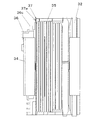
図1は、本発明の実施形態に係るモールドモータの概略構成を示す断面図である。図1に示すモータ1は、本発明のモールドモータの一例である。図2は、ステータ3の平面図である。
シャフト2は、一方の端部が第1のベアリング5に支持され、中央部分が第2のベアリング6に支持されている。シャフト2は、第1のベアリング5及び第2のベアリング6に対して回転可能である。シャフト2は、他方の端部がモータ1の外に位置している。シャフト2は、他端側に、負荷が取り付けられる。
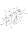
図4A及び図4Bは、端子ホルダー11の斜視図である。図4Aは、端子ホルダー11の、少なくとも第1面11k(端子保持穴11aを有する面)と第2面11m(第1のリード線保持溝11bを有する面)とが目視できるアングルで描画した図である。図4Bは、端子ホルダー11の、少なくとも第6面11p(第1面11kに対向する面)と第3面11n(第2面11mに対向する面)とが目視できるアングルで描画した図である。
図5は、端子12の側面図である。端子12は、ベース12a、スリット12b、舌部12c、爪12d、および爪12eを有する。端子12は、材料が金属等の導電材料であり、本実施の形態では銅である。端子12の材料は、リード線14の材料と同一材料、またはリード線14の材料との腐食電位差が小さい材料とすることが好ましい。これにより、リード線14と端子12とのイオン化傾向の差が小さいため、リード線14と端子12との接触部分において電食(ガルバニック腐食)が発生しにくくなる。
図6は、カバー13の斜視図である。
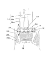
図7A〜図7Eは、端子ホルダー11,端子12,およびカバー13を、ステータ3のホルダー取付部36へ取り付ける過程を示す部分斜視図である。
本実施の形態にかかるモータ1は、ステータ3に壁37を有する。壁37は、端子ホルダー11をホルダー取付部36に取り付けた時に、第1のリード線保持溝11bを塞ぐ。このような構成としたことにより、ステータ3等を樹脂等のモータケーシング8で覆う際に、溶融した樹脂が第1のリード線保持溝11bに流入することを防ぐ。端子ホルダー11への樹脂の流入を防ぐことにより、端子ホルダー11内に位置するリード線14及び端子12が、樹脂の充填圧力により変形することを防ぐ。リード線14及び端子12の変形を防ぐことにより、リード線14と端子12との接続部分に隙間が生じず、接続状態が維持される。
2 シャフト
3 ステータ
4 ロータ
5 第1のベアリング
6 第2のベアリング
7 モータブラケット
8 モータケーシング
9 ベアリングブラケット
11 端子ホルダー
11a 端子保持穴
11b 第1のリード線保持溝
11c 第2のリード線保持溝
11d 爪
11e 段差部
11f 突起部
11g 穴
12 端子
12a ベース
12b スリット
12c 舌部
12d 爪
12e 爪
13 カバー
13a 本体部
13b 舌部
13c 舌部
13d 孔
13f 孔
13g 側壁
13h 凹部
14 リード線
14u U相リード線
14v V相リード線
14w W相リード線
31 ステータコア
32 ティース
33 コアバック
34 絶縁部材
34a 絶縁壁
34b 絶縁壁
35 コイル
36 端子取付部
37 壁
38 底部
40 被覆部材
50 接続部
60 樹脂
Claims (13)
- ステータと、
前記ステータに対して回転可能に支持されるロータと、
を有し、
前記ステータは、
環状のコアバックと、前記コアバックから径方向内側へ向けて伸びる複数のティースとを含むステータコアと、
前記コアバック及び前記ティースの一部を覆う絶縁部材と、
前記ステータコアに取り付けられるコイルと、
前記コイルに接続されるリード線と、
前記リード線が挿入されるスリットを有し、前記リード線を前記スリットに挿入することで前記リード線に接続される端子と、
前記リード線と前記端子とを保持し、前記絶縁部材に固定される端子ホルダーと、
を有し、
前記ロータは、
前記ステータコアの径方向内側に配置されたマグネットを含み、
前記端子ホルダーは、互いに対向する一対の側面に、前記リード線が挿入される第1のリード線保持溝及び第2のリード線保持溝を備え、
前記コアバック、前記絶縁部材、および前記端子ホルダーの少なくとも前記一対の側面のうち前記第1のリード線保持溝を備える側面が、モータケーシングにより覆われ、
前記リード線の一方の端部は、前記第1のリード線保持溝の中に配置され、
前記絶縁部材は、前記第1のリード線保持溝を覆う壁を有する、
モールドモータ。
- 請求項1記載のモールドモータであって、
前記端子ホルダーは、前記端子が挿入される端子保持穴を有し、
前記端子保持穴を塞ぐカバーを含む、モールドモータ。 - 請求項1に記載のモールドモータであって、
前記端子ホルダーは、爪を有し、
前記絶縁部材は、前記爪を支持する凹部を有する、モールドモータ。 - 請求項1に記載のモールドモータであって、
前記第1のリード線保持溝及び前記第2のリード線保持溝は、前記端子ホルダーの上端から下方に向けて切り欠かれる、モールドモータ。 - 請求項1に記載のモールドモータであって、
前記壁は、前記端子ホルダーの前記第1のリード線保持溝に対向する位置に凹部を有する、モールドモータ。 - 請求項2に記載のモールドモータであって、
前記カバーは、前記第2のリード線保持溝の一部を覆う側壁を有する、モールドモータ。 - 請求項2または6に記載のモールドモータであって、
前記第1のリード線保持溝は、前記壁と前記カバーとにより覆われる、モールドモータ。 - 請求項7に記載のモールドモータであって、
前記側壁は、前記第2のリード線保持溝に対向する位置に凹部を有する、モールドモータ。
- 請求項1〜8のうちいずれか一項に記載のモールドモータであって、
前記コイルは、電線材料がアルミニウムである、モールドモータ。 - 請求項1〜9のうちいずれか一項に記載のモールドモータであって、
前記リード線は、材料が銅である、モールドモータ。 - 請求項9乃至10に記載のモールドモータであって、
前記コイルと前記リード線とは、半田で接続され、
前記半田は、アルミニウムよりも低い腐食電位を有する、モールドモータ。 - 請求項11に記載のモールドモータであって、
前記コイルと前記リード線との接続部が、樹脂により覆われる、モールドモータ。 - 請求項1または2に記載のモールドモータであって、
前記端子保持穴に充填される接着剤を含む、モールドモータ。
Priority Applications (4)
| Application Number | Priority Date | Filing Date | Title |
|---|---|---|---|
| JP2012162155A JP5708585B2 (ja) | 2011-11-16 | 2012-07-21 | モールドモータ |
| KR1020120110247A KR101991516B1 (ko) | 2011-11-16 | 2012-10-04 | 몰드 모터 |
| CN201210457912.2A CN103117620B (zh) | 2011-11-16 | 2012-11-14 | 模制马达 |
| CN 201220600170 CN203086279U (zh) | 2011-11-16 | 2012-11-14 | 模制马达 |
Applications Claiming Priority (3)
| Application Number | Priority Date | Filing Date | Title |
|---|---|---|---|
| JP2011251156 | 2011-11-16 | ||
| JP2011251156 | 2011-11-16 | ||
| JP2012162155A JP5708585B2 (ja) | 2011-11-16 | 2012-07-21 | モールドモータ |
Publications (2)
| Publication Number | Publication Date |
|---|---|
| JP2013128391A JP2013128391A (ja) | 2013-06-27 |
| JP5708585B2 true JP5708585B2 (ja) | 2015-04-30 |
Family
ID=48778608
Family Applications (1)
| Application Number | Title | Priority Date | Filing Date |
|---|---|---|---|
| JP2012162155A Expired - Fee Related JP5708585B2 (ja) | 2011-11-16 | 2012-07-21 | モールドモータ |
Country Status (2)
| Country | Link |
|---|---|
| JP (1) | JP5708585B2 (ja) |
| CN (1) | CN203086279U (ja) |
Families Citing this family (7)
| Publication number | Priority date | Publication date | Assignee | Title |
|---|---|---|---|---|
| KR101991516B1 (ko) * | 2011-11-16 | 2019-06-20 | 니혼 덴산 테크노 모터 가부시키가이샤 | 몰드 모터 |
| JP5902726B2 (ja) * | 2014-01-15 | 2016-04-13 | トヨタ自動車株式会社 | 回転電機ステータ |
| JP6327988B2 (ja) * | 2014-07-17 | 2018-05-23 | アイチエレック株式会社 | 回転機 |
| JP6327989B2 (ja) * | 2014-07-17 | 2018-05-23 | アイチエレック株式会社 | 回転機 |
| JP6382698B2 (ja) * | 2014-11-26 | 2018-08-29 | トヨタ自動車株式会社 | 三相回転電機 |
| JP6230658B2 (ja) * | 2016-06-07 | 2017-11-15 | 三菱電機株式会社 | 制御装置一体型回転電機 |
| KR102448967B1 (ko) * | 2020-08-12 | 2022-09-28 | 주식회사 현대케피코 | 모터와 케이블의 연결구조 |
Family Cites Families (6)
| Publication number | Priority date | Publication date | Assignee | Title |
|---|---|---|---|---|
| JPS5127405A (ja) * | 1974-08-30 | 1976-03-08 | Hitachi Ltd | Kaitendenkyokoirunosetsuzokuho |
| JP3054972B2 (ja) * | 1992-01-16 | 2000-06-19 | 愛三工業株式会社 | ステップモータ |
| JP3412166B2 (ja) * | 1992-07-10 | 2003-06-03 | 松下電器産業株式会社 | 電動機 |
| JP3864380B2 (ja) * | 2002-09-25 | 2006-12-27 | ミネベア株式会社 | レゾルバの入出力端子構造及びそれを用いたレゾルバの結線方法 |
| JP4760566B2 (ja) * | 2006-06-21 | 2011-08-31 | 日本電産株式会社 | 巻線取付方法 |
| JP5528761B2 (ja) * | 2009-10-02 | 2014-06-25 | 日本電産テクノモータ株式会社 | モールドモータ |
-
2012
- 2012-07-21 JP JP2012162155A patent/JP5708585B2/ja not_active Expired - Fee Related
- 2012-11-14 CN CN 201220600170 patent/CN203086279U/zh not_active Expired - Fee Related
Also Published As
| Publication number | Publication date |
|---|---|
| JP2013128391A (ja) | 2013-06-27 |
| CN203086279U (zh) | 2013-07-24 |
Similar Documents
| Publication | Publication Date | Title |
|---|---|---|
| JP5708585B2 (ja) | モールドモータ | |
| JP5827840B2 (ja) | Vr型レゾルバ | |
| CN104541437B (zh) | 定子单元以及马达 | |
| JP6576773B2 (ja) | ポンプ装置 | |
| US11190076B2 (en) | Motor | |
| CN104380582B (zh) | 用于安装无刷电机的传感器基板的方法与结构 | |
| JP6248251B2 (ja) | アウタロータ型回転センサの信号線引出し構造 | |
| JP5384958B2 (ja) | モータ及びその製造方法 | |
| JP2017216759A (ja) | モータおよびポンプ装置 | |
| KR101798803B1 (ko) | 몰드 고정자, 몰드 전동기 및 공기 조화기 | |
| JP6452852B2 (ja) | 固定子、固定子の製造方法、電動機および空気調和装置 | |
| WO2017018066A1 (ja) | モータおよびモータの製造方法 | |
| KR101991516B1 (ko) | 몰드 모터 | |
| JP2018042362A (ja) | ステータユニット、モータ、およびファンモータ | |
| JP6606072B2 (ja) | 電気機械 | |
| CN206759258U (zh) | 马达 | |
| JP2019030143A (ja) | コネクタ及びコネクタを備えたモータ | |
| JP2019030144A (ja) | コネクタ及びコネクタを備えたモータ | |
| JP2019030141A (ja) | コネクタ及びコネクタを備えたモータ | |
| JP2020072543A (ja) | ロータ、ステータ、およびモータ | |
| JP6652360B2 (ja) | ポンプ装置 | |
| US10141811B2 (en) | Stator for electric motor, electric motor, and air conditioner | |
| JP2020178438A (ja) | モータ | |
| JP6232003B2 (ja) | 端子、端子構造体及び回転電機 | |
| JP2019030142A (ja) | コネクタ及びコネクタを備えたモータ |
Legal Events
| Date | Code | Title | Description |
|---|---|---|---|
| A625 | Written request for application examination (by other person) |
Free format text: JAPANESE INTERMEDIATE CODE: A625 Effective date: 20140425 |
|
| TRDD | Decision of grant or rejection written | ||
| A977 | Report on retrieval |
Free format text: JAPANESE INTERMEDIATE CODE: A971007 Effective date: 20150130 |
|
| A01 | Written decision to grant a patent or to grant a registration (utility model) |
Free format text: JAPANESE INTERMEDIATE CODE: A01 Effective date: 20150203 |
|
| A61 | First payment of annual fees (during grant procedure) |
Free format text: JAPANESE INTERMEDIATE CODE: A61 Effective date: 20150216 |
|
| R150 | Certificate of patent or registration of utility model |
Ref document number: 5708585 Country of ref document: JP Free format text: JAPANESE INTERMEDIATE CODE: R150 |
|
| R250 | Receipt of annual fees |
Free format text: JAPANESE INTERMEDIATE CODE: R250 |
|
| R250 | Receipt of annual fees |
Free format text: JAPANESE INTERMEDIATE CODE: R250 |
|
| LAPS | Cancellation because of no payment of annual fees |