JP5747112B1 - Wheelchair front leg suspension - Google Patents
Wheelchair front leg suspension Download PDFInfo
- Publication number
- JP5747112B1 JP5747112B1 JP2014167132A JP2014167132A JP5747112B1 JP 5747112 B1 JP5747112 B1 JP 5747112B1 JP 2014167132 A JP2014167132 A JP 2014167132A JP 2014167132 A JP2014167132 A JP 2014167132A JP 5747112 B1 JP5747112 B1 JP 5747112B1
- Authority
- JP
- Japan
- Prior art keywords
- frame
- wheelchair
- vertical
- frames
- vertical frame
- Prior art date
- Legal status (The legal status is an assumption and is not a legal conclusion. Google has not performed a legal analysis and makes no representation as to the accuracy of the status listed.)
- Expired - Fee Related
Links
- 210000001364 upper extremity Anatomy 0.000 title claims abstract description 53
- 239000000725 suspension Substances 0.000 title claims description 59
- 235000013351 cheese Nutrition 0.000 claims description 17
- 229910052782 aluminium Inorganic materials 0.000 claims description 12
- XAGFODPZIPBFFR-UHFFFAOYSA-N aluminium Chemical compound [Al] XAGFODPZIPBFFR-UHFFFAOYSA-N 0.000 claims description 12
- 230000008447 perception Effects 0.000 claims 1
- 229910052751 metal Inorganic materials 0.000 description 5
- 239000002184 metal Substances 0.000 description 5
- 239000004033 plastic Substances 0.000 description 3
- 210000002683 foot Anatomy 0.000 description 2
- 150000002739 metals Chemical class 0.000 description 2
- 210000004744 fore-foot Anatomy 0.000 description 1
- 210000004247 hand Anatomy 0.000 description 1
- 230000000474 nursing effect Effects 0.000 description 1
- 210000000707 wrist Anatomy 0.000 description 1
Images


Landscapes
- Handcart (AREA)
Abstract
【課題】病院や介護施設で患者等の緊急避難時に、車椅子で階段を移動させるため、従来の車椅子に階段移動用の補助装置を付け、階段移動が容易にした汎用の車椅子の共通した構造に適した簡便な緊急の階段用車椅子補助装置を提供する。
【解決手段】車椅子自体の強度のあるフレーム11を利用し、そこに使用に耐える強度を備えたL字型フックLと支持部を備えて車椅子に懸架できまた着脱できる車椅子前脚懸架装置を車椅子のフットレスト下側から組み込むことで車椅子と一体となるように装着し、車椅子の前脚側に新たな階段移動のための支持機能を加える。
【選択図】図4[PROBLEMS] To provide a common structure for a general-purpose wheelchair that facilitates stair movement by attaching an auxiliary device for stair movement to a conventional wheelchair to move the staircase with a wheelchair in case of emergency evacuation of a patient or the like in a hospital or a care facility Provide a suitable simple emergency staircase wheelchair assistance device.
The wheelchair itself has a frame 11 having a strength, and an L-shaped hook L having a strength that can withstand the use of the wheelchair and a support portion. It is installed from the bottom of the footrest so that it is integrated with the wheelchair, and a new support function for moving the stairs is added to the front leg side of the wheelchair.
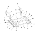
[Selection] Figure 4
Description
本発明は、車椅子に乗った要介護者をそのままで階段を避難移動しようとする時、車椅子の前脚側に着脱式の支持部を設けることで、より安全な車椅子の移動を補助する装置に関するものである。 The present invention relates to a device that assists safer movement of a wheelchair by providing a detachable support portion on the front leg side of the wheelchair when evacuating the stairs while keeping a care recipient in the wheelchair as it is. It is.
障がい者等の要介護者が使用している車椅子のまま階段移動するには、車椅子の前後左右から複数の人間による人力で持ち上げて移動するか、あるいは駅の階段等に設置してあるような大掛かりな電動車椅子昇降装置移動機で移動するか、あるいは蓄電池自走式駆動キャタピラの上に車椅子を乗せて移動する方法がある。 To move the stairs while using a wheelchair used by a care recipient such as a person with a disability, it must be lifted and moved by human power from the front, rear, left and right of the wheelchair, or it is installed on the stairs of a station, etc. move with extensive electric wheelchair lift device mobile, or there is a way to move by putting the wheelchair over the 蓄 battery self-propelled drive tracks.
患者もしくは身体障がい者等が車椅子に乗ったまま階段を移動するのは、車椅子が平面を押して移動するために製作されたもので、段差を乗り越えて車椅子を持ち上げて移動するための専用の持ち手もしくは支持部が備わっていないために階段移動には必要以上の人員が必要であったり、また階段の幅が狭い場合などがあったりして、階段移動は介助者には無理な姿勢を強いられ、困難で肉体的な負担も多い。それで車椅子が通れる幅の階段などでも少なくとも2名の人員で階段移動できるようにする。それを可能にするために前脚側に専用の車椅子の懸架装置を、介助者が最大限の力を発揮できるような位置に着脱できる支持部を設置すれば良い。階段上側の介助者は車椅子に既設の背部の備え付けのグリップを使用し、また階段下側の介助者には車椅子のフットレスト下側に簡単に着脱できる車椅子の本発明の車椅子前脚懸架装置を、階段移動の必要が生じたときに使用するようにすれば良い。 A patient or a person with a physical disability moves on the stairs while riding on a wheelchair because the wheelchair is designed to move by pushing on a flat surface, and a dedicated handle for moving the wheelchair over a step. or or a support section is required is more than necessary personnel to the stair movement in order to have such equipped, also with or there is such a case where the width of the staircase is narrow, the stairs move forced to unreasonable attitude in the caregiver It is difficult and physically burdensome. Therefore, even if the stairs are wide enough for wheelchairs to pass, stairs can be moved by at least two people. In order to make this possible, a support unit that can be attached to and detached from a dedicated wheelchair suspension on the front leg side can be installed at a position where the assistant can exert the maximum force. Stairs upper caregiver using grips equipped the existing back wheelchair, also a wheelchair front legs suspension system of the wheelchair of the present invention is a step-lower caregiver that can be easily attached to and detached from the footrest bets under side of the wheelchair, Use it when you need to move stairs.
車椅子のフットレストの下側から挿入する車椅子前脚懸架装置を着脱できるようにし、車椅子のフレームにL字型フックを懸架して、車椅子のフットレストを下側から支持するための支持フレームを備えて、車椅子を階段下側から支持できるようにした。 To be able to attach and detach the wheelchair front legs suspension system is inserted from the underside of the footrest bets wheelchair, by suspending the L-shaped hooks to wheelchair frame, a support frame for supporting the footrest bets wheelchair from below The wheelchair can be supported from below the stairs.
車椅子前脚懸架装置は、車椅子のフットレストの下側と床面との隙間の前方からあるいは横側から挿入できるように薄型にして、また車椅子のフレーム構造や連結部分を損なうことがないように、車椅子の形態に適合させて着脱できる構造にする。 Wheelchair front legs suspension system, in the thin so that it can be inserted from the front or from the side of the gap between the lower side and the floor surface of the footrest bets wheelchair, also so as not to impair the frame structure and connecting parts of the wheelchair, A structure that fits the wheelchair and is detachable.
また、階段を移動する場合は踊り場や廊下などの移動も含まれるので、車椅子前脚懸架装置は階段下側の介助者が手を離してもその位置で保たれるようにゴム紐で吊るようにして車椅子と一体となるようにし、平面では車椅子前脚懸架装置を設置したまま前進可能にした。 In addition, moving the stairs includes movements such as landings and hallways, so the wheelchair nose landing gear suspension should be hung with a rubber strap so that it can be held in place even if the assistant under the stairs releases his hand. The wheelchair is integrated with the wheelchair, and on the flat surface, the wheelchair front leg suspension is installed and can be moved forward.
車椅子前脚懸架装置は、幅や長さのサイズの異なった車椅子により対応できるように、回転するアームを設置してその先端のL字型フックで車椅子のフレームに懸架できるようにし、また車椅子のフットレストまたはその下端のフレームを受け止めるための広めのプレートPを設置した。 The wheelchair front leg suspension system is equipped with a rotating arm so that it can be supported by wheelchairs of different widths and lengths, so that it can be suspended on the wheelchair frame with an L-shaped hook at the tip, and the wheelchair footless A wide plate P was installed to receive the frame at the bottom or the bottom of the frame.
車椅子前脚懸架装置の車椅子のフレームへの前方での着脱を容易とするために、車椅子前脚懸架装置にL字型フックとハンドルフレームHが一体となって可動するムーブメントを設置した。 In order to make it easy to attach and detach the wheelchair front leg suspension to the wheelchair frame in front, a movement in which the L-shaped hook and the handle frame H are movable is installed on the wheelchair front leg suspension.
車椅子前脚懸架装置が、車椅子の下で前後方向に不用意に移動しないように、車椅子前脚懸架装置のL字型のフックを車椅子のフレーム6とフレーム7がクロスする場所に引っ掛けるようにし、L字型フックがフレーム6よりは前方に、またハンドルフレームがフットレスト前方で垂直となって後方への移動を制限するように設置した。
In order to prevent the wheelchair front leg suspension device from inadvertently moving in the front-rear direction under the wheelchair, the L-shaped hook of the wheelchair front leg suspension device is hooked on the position where the
L字型のフックは回転する第3、第4縦フレームMの一端に設置し、また他端にハンドルフレームHを設置して一体となるムーブメントによって構成され、ハンドルフレームHを回転するとL字型フックも連動して回転すると共に、L字型フックの回転調整が階段下の介助者側でできるようにした。
L-
車椅子前脚懸架装置が、幅と長さの異なる多様な車椅子のフットレストを下側から支持できるように、車椅子前脚懸架装置に幅8cm前後長さ22cmのプレートを設けて、その上でフットレスト下端KまたはフットレストFを下側から支持できるようにする。 Wheelchair front leg suspension system, to allow support width and length of different diverse wheelchair footrest from below, by providing a plate width 8cm longitudinal length 22cm wheelchair front leg suspension system, footrest preparative lower K on it or footrest bets F to be supported from the lower side.
車椅子前脚懸架装置で介助者が車椅子を階段下側から支持できるように、車椅子前脚懸架装置の支持部がフットレストの前方でフットレストと適度な間隔を設けて設置され、介助者が支持部を手で把持できるようにする。 The support part of the wheelchair front leg suspension device is installed in front of the footrest with an appropriate distance from the footrest so that the assistant can support the wheelchair from the lower side of the stairs with the wheelchair front leg suspension system. Be able to grip.
車椅子前脚懸架装置全体をフットレストに懸架できるように、ゴム紐を張り渡してフットレストの上側に架け、また要介護者の足の下で架かって、吊るせるようにゴム紐を設置する。 The entire wheelchair before leg suspension device so that it can be suspended on the footrest, hung on the upper side of the footrest door and stretched the rubber straps, also spans under the care recipient of the foot, to install a rubber cord as Tsuruseru.
一辺を5cm程度として直角に連結したL字型フックを構成して、ムーブメントを回転しアームフレームを垂直にした時に、アームフレームに直角に連結されて水平となるフレーム11の他端で直角に連結されたL字型フックが、水平に対し山形を形成して内角が地上を向き、車椅子のフレーム7に対し直角となるようにした。
Construct an L-shaped hook with a side of about 5cm and connected at right angles, and when the movement is rotated to make the arm frame vertical, it is connected at right angles to the other end of the
平行する車椅子の左右のフレーム7にL字型フックを、フレーム7の内側でアームフレームが回転し内角が内側から回転しフレーム7の上側から引っ掛ける場合はL字型フックLとし、フレーム7の左右の外側からアームフレームが回転し内角が外側から回転しフレーム7の上側から引っ掛ける場合は逆L字型フックRとした。
L-shaped hooks are used on the left and
車椅子前脚懸架装置を平面に置いた時、回転移動したL字型フックの内角の頂点までの地上高を懸架する車椅子のフレーム7の地上高よりも低くして、ゴム紐で合わせて吊るす時全体が地上から離れて懸架されるようにした。
When the wheelchair front leg suspension is placed on a flat surface, the ground height to the top of the inner corner of the L-shaped hook that has been rotated is lower than the ground height of the
車椅子に階段移動用の車椅子前脚懸架装置を着脱することで、適宜に車椅子が新たな階段移動用の車椅子として使用可能となり、車椅子の前後の介助者で車椅子に要介護者を乗せたまま階段移動を可能にする。 The wheelchair can be used as a new wheelchair for moving stairs by attaching / detaching the wheelchair front leg suspension device for moving stairs to / from the wheelchair. Enable.
病院や介護施設などでの非常時に階段移動を強いられる時、小型で簡便な車椅子前脚懸架装置を常備しておくことで、車椅子のままでの災害時避難用具として使用できる。 When you are forced to move stairs in an emergency at a hospital or nursing facility, you can use it as a disaster evacuation tool in a wheelchair by keeping a small and simple wheelchair front leg suspension device.
以下、本発明に係る車椅子前脚懸架装置のいくつかの実施形態を説明する。Several embodiments of the wheelchair front leg suspension device according to the present invention will be described below.
[第1実施形態]
図1、図2、及び図4では、汎用の車椅子の座幅を約40cmとした場合、アルミパイプ等からなる車椅子の座幅よりも短めの一対の長さ約30cmの後フレーム1と前フレームSを平行に配置して、それぞれの両端に1個ずつ、計4個のクロスパイプジョイントJをそれぞれ連結して、更にそれら4個のクロスパイプジョイントJから後フレーム1と前フレームSのそれぞれの延長線上にそれぞれ長さ約10cmの第1延長フレーム3を連結して全長約50cmの平行するフレームを構成し、左側の2個の第1延長フレーム3の端部に長さ約20cmの第1縦フレーム2を、右側の2個の第1延長フレーム3の端部に第2縦フレーム2をそれぞれ第1延長フレーム3に対して直角となるようにまたそれぞれが平行となるように連結して、車椅子の座幅よりも広い幅約50cmで長さ約20cmの長方形状の枠フレームを構成した。
[First Embodiment]
In FIG. 1, FIG. 2, and FIG. 4, when the seat width of a general-purpose wheelchair is about 40 cm, a pair of
前記長方形状の枠フレームの約20cm間隔で向き合う後フレーム1の両端の一対のクロスパイプジョイントJと、前フレームSの両端の一対のクロスパイプジョイントJ間に、後フレーム1と前フレームSに対して直角となるように、また、第1、第2縦フレーム2に対して平行となるように、第3、第4縦フレームМを回転可能に挿入した。
A pair of cross pipes joints J at both ends of the
前記第3、第4縦フレームМの両端に長さ約15cmの複数のフレームをそれぞれ直角でそれぞれが平行となるように連結して、前フレームS側のフレームをハンドルフレームHとし、後フレーム1側のフレームをアーム部Aとアーム部Bから成るアームフレームとした。
Said third, and a plurality of frames across a length of about 15cm of the fourth vertical frame М connected to respectively a right angle respectively parallel, before the frame of the frame S side and handle frame H, the
アーム部Aとアーム部Bの他端で第2延長フレーム11を直角に連結し、第2延長フレーム11は第3、第4縦フレームМと平行となるように、そして前記第3、第4縦フレームМを延伸するようにアーム部A、Bと連結し、その一方の先端が第3、第4縦フレームМの前側のハンドルフレームHから約47cmとなるようにした。
The
前記長方形の枠フレームを水平に伏した状態で、アーム部Aとアーム部Bが回転して前記アームフレームが枠フレームに直角にそして垂直に立つ位置に来る場合に、第2延長フレーム11の先端から約5cmの長さで内角θ約90度を構成するL字型フックLが第2延長フレーム11に直角となるように連結されて、L字型部分が水平面に対して山形を形成し、L字型フックLの内角が地上と向き合って山のように突き出して、またL字型フックLの先端がそれぞれ第1、第2縦フレーム2に直角に向くように設置して、クロスパイプジョイントJに挿入されたムーブメントのハンドルフレームHとL字型フックLが、長方形の枠フレームの枠外で前フレームSの前側のハンドルフレームHを回転することで後フレーム1の後側のアーム部A、Bが連動して回転して、L字型フックLの内角によって車椅子のフレーム7に上から懸架されるように構成した(図3参照)。
Wherein in a state where the frame member was lay horizontally rectangular, if you rotate the arm portion A and the arm portion B that comes right angle and vertically standing position on the arm frame is frame member, the tip of the
汎用の車椅子のフレーム7の地上高を約20cmとすると、アーム部A、Bを垂直に立てた時水平面に対し山形となるL字型フックLの内角がフレーム7の上で懸架される地上高を、約15cmとなるようにした。
When about 20cm the ground clearance of a general-
但し、車椅子前脚懸架装置のサイズまたは構成について、フレームМまたはムーブメントのL字型フックLからハンドルフレームHまでの長さを約47cmとしたが、前フレームSは支持フレームを兼ねるので、L字型フックLの内角によって車椅子のフレーム7に上から懸架され車椅子のフレーム6で制止される状態で、ハンドルフレームHと前フレームSがフットレストの前方で握れるように間隔を空けて配置され、手の甲または指先が入るようにすることが必要である。
However, the size or configuration of the wheelchair front leg suspension system has been set to about 47cm in length to the handle frame H from the frame М or Mubumen bets L-shaped hooks L, since the previous frame S is also serves as a supporting frame, L-shaped The handle frame H and the front frame S are arranged at a distance so that they can be held in front of the footrest while being suspended from the
前記第2延長フレーム11の先端でそれぞれ第1、第2縦フレーム2側である長方形の枠フレームの外側を向いてそれぞれが反対向きとなっている一対のL字型フックLに於いて、一対のL字型フックLの一方を逆向けにして、L字型フックLの先端の向きを左右いずれかに揃えて設置しても良い。
In the pair of L-shaped hooks L facing the outside of the rectangular frame frames on the first and second
アーム部Aとアーム部Bにしたのは、細いアルミパイプ等を使用した時のフレームの懸架強度を増すためであり、またアームフレームとハンドルフレームHが長方形の枠フレームの外側に位置するのは、フレームМのクロスパイブジョイントJでのスライド移動を制限するためである。 Arm portions to that in the A and the arm portion B is for increasing the suspension strength of the frame when using a thin aluminum pipe or the like, also the arm frame and the handle frame H is located outside the side of the rectangular frame member This is for restricting the slide movement at the cross pipe joint J of the frame М.
前記長方形の枠フレームで第1、第2縦フレーム2に直角に連結されたそれぞれの第1延長フレーム3間に、第3、第4縦フレームМに接触して第3、第4縦フレームМの回転を妨げないように一対のプレートPを固定した。
The first in frame frame rectangle, between the second
長方形のプレートPの左右の幅は約8cmで、前後の長さは第3、第4縦フレームMよりも長く約22センチとしたが、幅をもう少し広くして第3、第4縦フレームMにもプラインドリベット等で固定するほうが長方形の枠フレームがより強度を増す。またプレートPがアルミ板などの金属の場合は、フットレストまたはフットレストフレームKを受ける接触面に金属間の摩擦音などを防ぐためにプレートPの上面に繊維質のカーペットなどを貼ると良い。 In left and right width of about 8cm rectangular plate P, the third the length of the front and rear, has been a long about 22 cm than the fourth vertical frame M, the third and little wider, fourth vertical frame M the rectangular frame frame is better to be fixed in the plastic India rivets also increases the more strength. When the plate P is a metal such as an aluminum plate, a fibrous carpet or the like is preferably attached to the upper surface of the plate P in order to prevent frictional noise between metals on the contact surface that receives the footrest or the footrest frame K.
第1、第2縦フレーム2間に、一対のプレートPの上に被せるようにゴム紐Gを連結してゴム紐Gを車椅子のフットレストFに上側から架けることで車椅子前脚懸架装置を吊るせるようにした。
A rubber cord G is connected between the first and second
汎用の車椅子のフレーム7の地上高を約20cmとすると、車椅子前脚懸架装置を地上に置きアーム部A、Bを垂直に立てた時水平面に対し山形となるL字型フックLの内角までの地上高は、フレーム7の地上高よりも低い約15cmである。
When about 20cm the ground clearance of a general-
ムーブメントはアーム部Aとアーム部Bを備えているが、アルミパイブ等からなるフレームを太くすることでアーム部Bのみにすることも可能である。但しアーム部Aのみにした時あるいはアーム部Bのみにした時、L字型フックLからハンドルフレームHまでのムーブメントの全長は、約47cmとする。 Mubumen bets is provided with an arm portion A and the arm portion B, it is also possible to only the arm B by thick frames consisting Arumipaibu like. However when only or arm B when the only the arm portion A, the full length of Mubumen bets from the L-shaped hook L to handle frame H is about 47cm.
ムーブメントの第3、第4縦フレームМは、クロスパイプジョイントJに挿入されて回転しスライドするが、L字型フックL側(後側)ではアーム部Bによって、前側ではハンドルフレームHでそのスライド移動幅は制限される。 Mubumen bets third, fourth vertical frame М is slid to rotate is inserted in the cross pipe joint J, the L-shaped hooks L side (rear side) in the arm section B, the front side in the handle frame H The slide movement width is limited.
[第2実施形態]
図5及び図6では、汎用の車椅子の座幅を約40cmとした場合、アルミパイプ等からなる車椅子の座幅よりも短めの一対の長さ約30cmの後フレーム1と前フレームSを前後に平行に配置して、それぞれの左端間及び右端間に長さ約20cmの第1、第2縦フレーム4をそれぞれ後フレーム1、前フレームSに直角に連結して長方形の枠フレームを構成し、長さ約30cmの後フレーム1と前フレームSの両端の延長線上にそれぞれ1個ずつ、計4個の長さ約10cmの第1延長フレーム5を連結し、車椅子の座幅よりも広い全長約50cmの互いに平行なフレームを構成し、該フレームの両端にそれぞれ1個ずつ、計4個のチーズパイブジョイントТを連結した。
[Second Embodiment]
5 and 6, when the seat width of a general-purpose wheelchair is about 40 cm, the
約20cm間隔で向き合う、後フレーム1の両端の一対のチーズパイブジョイントТと前フレームSの両端の一対のチーズパイブジョイントТ間に、後フレーム1と前フレームSには直角となるように、また第1、第2縦フレーム4には平行となるように第3、第4縦フレームNを回転しスライド可能に挿入して、それら第3、第4縦フレームNの前後両端に長さ約15cmのフレームを前記第3、第4縦フレームNに直角で互いに平行となるように連結して、前端側のフレームをハンドルフレームHとし、後端側の一対のフレームをアーム部Aとアーム部Bとした。
Facing at about 20cm interval, between a pair of cheese Pas Eve joint Т across the pair of cheese Pas Eve joint Т the previous frame S at both ends of the
アーム部Aとアーム部Bの他端で第2延長フレーム11をアーム部Aとアーム部Bに直角に連結し、第2延長フレーム11は第3、第4縦フレームNと平行となるようにそして前記第3、第4縦フレームNを延伸するように連結し、第2延長フレーム11の先端からハンドルフレームHまでの全長を約47cmとなるようにした。
The
前記長方形の枠フレームを水平に伏した状態で、アーム部Aとアーム部Bが回転して前記長方形の枠フレームに対して直角にそして垂直に立つ位置に来る場合に、第2延長フレーム11の先端から約5cmの長さで内角θ約90度を構成する逆L字型フックRが第2延長フレーム11に直角となるように該第2延長フレーム11に連結されて水平面に対して山形を形成し、逆L字型フックRの内角が地上と向き合って山のように突き出して、また逆L字型フックRの先端がそれぞれ第1、第2縦フレーム4に直角に向くように設置されて、長方形の枠フレームの前フレームSの前側のハンドルフレームHを回転することで後フレーム1の後側のアーム部A、Bが連動して回転して、逆L字型フックRの内角によって車椅子のフレーム7に上から懸架されるように構成した。
Wherein in a state where the frame member was lay horizontally rectangular, when the arm portion A and the arm portion B rotates to come to a right angle and perpendicularly standing position relative to the frame the frame of the rectangle, the
汎用の車椅子のフレーム7の地上高を約20cmとすると、アーム部A、Bを垂直に立てた時水平面に対し山形となる逆L字型フックRの内角までの地上高は、フレーム7の地上高よりも低い約15cmとした。
When about 20cm the ground clearance of a general-
但し、車椅子前脚懸架装置のサイズまたは構成について、フレームNまたはムーブメントの逆L字型フックRからハンドルフレームHまでの長さを約47cmとしたが、前フレームSは支持フレームを兼ねるので、逆L字型フックRの内角によって車椅子のフレーム7に上から懸架され車椅子のフレーム6で制止される状態で、ハンドルフレームHと前フレームSがフットレストの前方で握れるように間隔を空けて配置され、手の甲または指先が入るようにすることが必要である。
However, with the size or configuration of the wheelchair front leg suspension system, although the frame N or Mubumen bets about 47cm in length from the reversed L-shaped hooks R to handle frame H, since the previous frame S is also serves as a supporting frame, The handle frame H and the front frame S are spaced from each other so that the handle frame H and the front frame S can be gripped in front of the footrest while suspended from the
一対の逆L字型フックRはL字型フックに替えることも可能で、また片方をL字型フックL、もう片方を逆L字型フックRにしても良い。 The pair of inverted L-shaped hooks R can be replaced with L-shaped hooks, and one of them can be an L-shaped hook L and the other can be an inverted L-shaped hook R.
アームフレームをアーム部Aとアーム部Bにしたのは、細いアルミパイプ等を使用した時のフレームの懸架強度を増すためであり、またアーム部BとハンドルフレームHが長方形の枠フレームの外側に位置するのは、第3、第4縦フレームNのチーズパイブジョイントJでのスライド移動を制限するためである。 To that of the arm frame to the arm portion A and the arm portion B is thin is for increasing the suspension strength of the frame when using the aluminum pipe or the like, also the outer side of the frame member of the arm portion B and the handle frame H is rectangular The reason is that the sliding movement at the cheese pipe joint J of the third and fourth vertical frames N is limited.
前記長方形の枠フレームの左側、右側それぞれの一対の第1延長フレーム5間に、第3、第4縦フレームNに接触して該第3、第4縦フレームNの回転を妨げないように長方形のプレートPを1個ずつ固定した。 A rectangular shape that touches the third and fourth vertical frames N between the pair of first extension frames 5 on the left and right sides of the rectangular frame so as not to prevent the rotation of the third and fourth vertical frames N. the flop rate P was fixed one by one.
長方形のプレートPの左右の幅は約8cmで、前後の長さは第1、第2縦フレーム4よりも長く約22センチとしたが、幅をもう少し広くして第1、第2縦フレーム4にもプラインドリベット等で固定するほうが長方形の枠フレームがより強度を増す。またプレートPがアルミ板などの金属の場合は、金属間の摩擦音などを防ぐためにフットレストを受けるプレートPの接触面に繊維質のカーペットなどを貼ると良い。
In left and right width of about 8cm rectangular plate P, first the length of the front and rear, has been a long about 22 centimeters than the second
第3、第4縦フレームN間に、一対のプレートPの上に被せるようにゴム紐Gを第3、第4縦フレームNの回転を阻害しないように固定せず連結して、ゴム紐Gを車椅子のフットレストFに上側から架けることで車椅子前脚懸架装置を吊るせるようにした。 The rubber cord G is connected between the third and fourth vertical frames N without being fixed so as to cover the pair of plates P so as not to inhibit the rotation of the third and fourth vertical frames N. The wheelchair front leg suspension device can be hung on the footrest F of the wheelchair from above.
汎用の車椅子のフレーム7の地上高を約20cmとすると、アーム部A、Bを垂直に立てた時水平面に対し山形となる逆L字型フックRの内角までの地上高は、フレーム7の地上高よりも低い約15cmである。
When about 20cm the ground clearance of a general-
ムーブメントはアーム部Aとアーム部Bを備えているが、アルミパイブ等からなるフレームを太くすることでアーム部Bのみにすることも可能である。但しこの時、逆L字型フックRからハンドルフレームHまでの距離は、約47cmとする。 Mubumen bets is provided with an arm portion A and the arm portion B, it is also possible to only the arm B by thick frames consisting Arumipaibu like. However, at this time, the distance from the inverted L-shaped hook R to the handle frame H is about 47 cm.
ムーブメントの第3、第4縦フレームNは回転しスライドするが、アーム部BとハンドルフレームHでそのスライド幅は制限される。 Mubumen bets Third, fourth vertical frame N to rotate and slide, the slide width arm B and the handle frame H is limited.
第3、第4縦フレームN間に、一対のプレートPを被せるようにゴム紐Gを連結して、第3、第4縦フレームNの回転を妨げないように輪通ししてゴム紐Gを張り渡して、ゴム紐Gを車椅子のフットレストFに上側から架けることで車椅子前脚懸架装置を吊るせるようにした。 A rubber cord G is connected between the third and fourth vertical frames N so as to cover a pair of plates P, and the rubber cord G is looped around so as not to prevent the rotation of the third and fourth vertical frames N. It was stretched and the wheelchair front leg suspension device was hung by hanging the rubber cord G on the footrest F of the wheelchair from above.
[第3実施形態]
図7では、汎用の車椅子の座幅を約40cmとした場合、アルミパイプ等からなる車椅子の座幅よりも短めの一対の長さ約30cmの後フレーム1と前フレームSを平行に配置して、それぞれの両端間に長さ約20cmの第1、第2縦フレーム12それぞれ直角に連結して長方形の枠フレームを構成し、長さ約30cmの後フレーム1、前フレームSの両側の延長線上にそれぞれ長さ約10cmの第1延長フレーム5を一対ずつ連結し、左側の第1延長フレーム5の端部間に長さ約20cmの第3縦フレーム10を、右側の第1延長フレーム5の端部間に長さ約20cmの第4縦フレーム10を連結して、全体として車椅子の座幅よりも広い幅約50cmの三つの連合した長方形となるフレームを構成して、前記第3、第4縦フレーム10にそれぞれチーズパイブジョイントТを回転とスライド可能に挿入した。
[Third Embodiment]
In FIG. 7, when the seat width of a general-purpose wheelchair is about 40 cm, the
前記チーズパイブジョイントТに、前記第3、第4縦フレーム10と直角になるように約15cmのアームフレームCを連結して、前記アームフレームCの他端に長さ約25cmの第2延長フレームXを前記アームフレームCに直角にまた前記フレーム10を延伸するように連結し、第2延長フレームXその先端から前フレームSまでの間隔を約45cmとなるように連結して、前記長方形の枠フレームを水平に伏した状態でアームフレームCが回転して後フレーム1、前フレームSに直角にそして垂直に立つ位置に来る場合に、第2延長フレームXの先端から約5cmの長さで内角θ約90度を構成する逆L字型フックRが第2延長フレームXに直角となるように逆L字型フックRが連結されて水平面に対して山形を形成し、逆L字型フックRの内角が地上と向き合って山のように突き出して、また逆L字型フックRの先端がそれぞれ第1、第2縦フレーム12に直角に向くように設置されて、一体となる一対のムーブメントが、アームフレームCを回転することで逆L字型フックRの内角によって車椅子のフレーム7に上から懸架されるように構成した。
An arm frame C of about 15 cm is connected to the cheese pipe joint Т so as to be perpendicular to the third and fourth
汎用の車椅子のフレーム7の地上高を約20cmとすると、アームフレームCを垂直に立てた時水平面に対し山形となる逆L字型フックRの内角までの地上高は、フレーム7の地上高よりも低い約15cmとした。
If the ground height of the
但し、車椅子前脚懸架装置のサイズまたは構成について、逆L字型フックRから前フレームSまでの間隔を約45cmとなるようにしたが、前フレームSは支持フレームを兼ねるので、逆L字型フックRの内角によって車椅子のフレーム7に上から懸架され車椅子のフレーム6で制止される状態で、前フレームSは常に車椅子のフットレスト先端から離れて手の甲または指先が入る間隔が必要になる。
However, with the size or configuration of the wheelchair front leg suspension system has been to the distance from the inverted L-shaped hook R up to the previous frame S becomes about 45cm, since the previous frame S is also serves as a supporting frame, inverted L-shape the internal angle of the hook R in a state of being restrained by the
一対の逆L字型フックRはL字型フックに替えることも可能で、また片方のみをL字型フックLにして設置しても良い。 The pair of inverted L-shaped hooks R can be replaced with L-shaped hooks, or only one of them can be installed as an L-shaped hook L.
第1、第2実施形態で用いたアーム部A、Bと違って、本実施形態ではアームフレームCが単数であるが、これは、太いアルミパイプ等を使用しムーブメントの懸架のための強度が足りることが前提での構成である。 First, arm A used in the second embodiment, unlike is B, the strength for the present but in the embodiment is the arm frame C is singular, this is Mubumen bets suspension using a thick aluminum pipe or the like It is a premise that there is enough.
前記長方形の枠フレームの後フレーム1側の一対の第1延長フレーム5とフレームS側の一対のフレーム5間に、長さ約22cm幅約8cmの長方形の一対のプレートPを固定した。但しプレートPは、逆L字型フックRの内角の頂点がフレーム12の垂直線上辺りにまで来るように、アームフレームCの回転を妨げないように設置する。
A pair of rectangular plates P having a length of about 22 cm and a width of about 8 cm were fixed between the pair of first extension frames 5 on the
長方形のプレートPの左右の幅は約8cmで、前後の長さは第1、第2縦フレーム12よりも長く約22センチとしたが、幅をもう少し広くして第1、第2縦フレーム12にもプラインドリベット等で固定するほうが長方形の枠フレームがより強度を増す。またプレートPがアルミ板などの金属の場合は、フットレストを受ける上面に繊維質のカーペットなどを貼ると良い。
In left and right width of about 8cm rectangular plate P, first the length of the front and rear, has been a long about 22 centimeters from the second
一対の第3、第4縦フレーム10間に、一対のプレートPの上に被せるようにゴム紐Gを第3、第4縦フレーム10に連結して、ゴム紐Gを車椅子のフットレストFに上側から架けることで車椅子前脚懸架装置を吊るせるようにした。
A pair third, between fourth
第3、第4縦フレーム10に挿入されたチーズパイプジョイントТが、前フレームS側でスライド移動を制限された時、ムーブムントの逆L字型フックRから前フレームSまでの直線上の間隔は約45cmである。
When the cheese pipe joint Т inserted in the third and fourth
但し車椅子前脚懸架装置のサイズまたは構成について、前フレームSは支持フレームを兼ねるので、前フレームSは常に車椅子のフットレスト先端から離れて手の甲または指先が入り握れる間隔が必要になる。 However with the size or configuration of the wheelchair front leg suspension system, front frame S is also serves as a supporting frame, the previous frame S is regularly need gripped interval contains the back of the hand or finger away from the footrest preparative tip the wheelchair.
汎用の車椅子のフレーム7の地上高を約20cmとすると、アームフレームCを垂直に立てた時水平面に対し山形となる逆L字型フックRの内角までの地上高は、約15cmである。
If the ground height of the
図面に記していないが、チーズパイブジョイントТの支持フレームS側へのスライド移動を制限するための固定金具を設ける。 Although not shown in the drawing, a fixing bracket is provided for restricting the sliding movement of the cheese pipe joint Т to the support frame S side.
次に本発明に係る車椅子前足懸架装置の具体的な使用方法について説明する。
車椅子で階段を下りる場合に、前進方向で前輪キャスターを階段踊り場からの段差の手前まで移動する。もう一人の介助者は階段下側に移動して車椅子前脚懸架装置を平面に伏した状態で、フットレストFの下側に車椅子前脚懸架装置を移動する。この際、フットレストFの地上高は使用状態によって様々なので、L字型フックLの突端がフットレストFの下部やフレーム9に当たらないように、前進方向を向いた自在の前輪キャスターの前に、車椅子前脚懸架装置を車椅子の左右いずれかの横側から差し込むように滑り込ませると良い。但し、それでも車椅子前脚懸架装置をフットレストFの下側に挿入できない場合は、後方の介助者に車椅子を後傾させて前輪キャスターを宙に上げてもらえば良い。この際、車椅子を前進方向で停止するとしたのは、車椅子の前輪である自在キャスターは、フットレストとキャスターとの間に最も広い空間を構成し、またキャスターが上から見るとフレーム9と平行にあるいは一直線上に並んで、アーム部Aまたはアーム部Bの回転とL字型フックLまたは逆L字型フックRの車椅子のフレーム7への懸架を最も妨げない状態となるからである。
Next, a specific method of using the wheelchair forefoot suspension according to the present invention will be described.
When going down the stairs in a wheelchair, move the front wheel casters to the front of the step from the stair landing in the forward direction. The other one of the caregiver to move in a stepwise downward in a state in which lay in the plane of the wheelchair front leg suspension device to move the wheelchair front leg suspension system below the footrest bets F. In this case, since the ground clearance of the footrest DOO F is various by use, as the protruding end of the L-shaped hook L does not hit the bottom and the frame 9 of the footrest F, before the free front wheel casters facing forward, The wheelchair front leg suspension device may be slid so as to be inserted from either the left or right side of the wheelchair. However, if the wheelchair front leg suspension device cannot be inserted below the footrest F, the rear wheeler can tilt the wheelchair and raise the front wheel caster in the air. At this time, the free wheel caster, which is the front wheel of the wheel chair, is said to stop the wheel chair in the forward direction, and forms the widest space between the footrest and the caster, and when viewed from above, the caster is parallel to the frame 9 or This is because, in a straight line, the rotation of the arm portion A or the arm portion B and the suspension of the L-shaped hook L or the inverted L-shaped hook R to the
階段下の介助者は、平面に伏した車椅子前脚懸架装置のハンドルフレームHを両手で持って、右手または左手をそれぞれ90度回転すると、同時にムーブメントのL字型フックLの先端が、車椅子の内側から左右のフレーム7の外側に向けて直角方向で円回転して、アーム部A、Bが垂直に立とうとするので、その直前にハンドルフレームHを手首の力でL字型フック内角をフレーム7よりも高く持ち上げる。
The caregiver under the stairs, with the handle frame H wheelchair front legs suspension system which lay on planes with both hands, the right hand or left hand respectively rotate 90 degrees, the tip of simultaneously Mubumen bets L-shaped hooks L, wheelchair frame by a circle rotates at a right angle direction from the inside to the outside of the left and
ハンドルフレームHを持ってL字型フックLの先端を持ち上げて、フレーム7に接触しないように回転して、L字型フックLの先端がフレーム7の上にオーバーハングする様にハンドルフレームHを左右外側に回転すると、アーム部A、Bがフレーム7に内側から当たってハンドルフレームHの回転が止まるので、そのままL字型フックLの位置を下げると、L字型フックLの内角を車椅子のフレーム6よりも奥でフレーム7の上側からを引っ掛けることができる。
Lift the tip of the L-shaped hooks L with the handle frame H, rotated so as not to contact the
次に階段下側の介助者は、ゴム紐GをフットレストFの上側でかつ要介護者の足の下になるように架けると、車椅子前脚懸架装置の全体がL字型フックLとゴム紐Gで懸架されて宙に浮くことになる。 Then stairs under side of the caregiver, when subjected to be the rubber string G below the upper a and the care recipient's foot footrest DOO F, whole L-shaped hooks L and rubber bands wheelchair front leg suspension system Suspended by G and floats in the air.
このとき車椅子前脚懸架装置のL字型フックを車椅子に架ける位置は、車椅子のフレーム7の上側で、そしてフレーム6よりは車椅子の奥側でL字型フックLを架けるが、車椅子のサイズが大きい場合は車椅子のフレーム9に懸架することも可能である。但しこの場合L字型フックLが車椅子のフレーム9を前後に不用意にスライド移動する可能性があるので注意が必要である。
At this time, the position where the L-shaped hook of the wheelchair front leg suspension device can be mounted on the wheelchair is on the upper side of the
一方ハンドルフレームHと前フレームSは、車椅子のフットレストFの先端よりは前方に位置していて、L字型フックは車椅子のフレーム6で車椅子の前方への移動が制限されているので、実際の使用では車椅子は後傾していて前輪側が上がっているため、車椅子前脚懸架装置は車椅子のフレーム6で前方への移動を制限されて、またハンドルフレームHが車椅子のフットレストで後方への移動を制限されるので、定位置を保つことができる。
On the other hand, the handle frame H and the front frame S are positioned in front of the tip of the footrest F of the wheelchair, and the L-shaped hook is restricted by the
汎用の車椅子ではフットレストFのフレーム8が、フレーム9によって連結されているが、一部のリクライニングタイプの車椅子ではフットレストFが可動式となっていて、フレーム9が無くてフットレストFとフレーム8とが跳ね上げ可動式または分離式の場合もあるが、車椅子の大小のサイズに適用できるようにプレートの幅を約8cm長さを22cmとしているので、車椅子のフレーム7とフレーム6にL字型フックLを懸架し、またフットレストFまたはフットレスト下端Kを幅広で縦長のプレートPが車椅子を下側から支持し、前フレームSを介助者が握ることができるので、車椅子を階段下側から支持することができる。
介助者は、車椅子をフットレストFの先端と車椅子前脚懸架装置の前フレームSとの隙間に手を差し込んで前フレームSを持って引き上げて、車椅子の前輪を宙に浮かせて階段を下りる。この時階段上の介助者は車椅子の既設のグリップを持って後輪を宙に浮かせるが、介助者の階段の上下の立ち位置からすると車椅子は後傾することになって、要介護人は後ろ側に傾くが車椅子の上で姿勢は安定する。 Caregiver is pulled with a previous frame S by inserting the hand wheel chair into the gap between the previous frame S of the tip and the wheelchair front leg suspension system footrest DOO F, going down stairs float in the air to the front wheels of the wheelchair. At this time, the assistant on the stairs holds the wheelchair's existing grip and lifts the rear wheel in the air, but the wheelchair tilts backward from the upper and lower standing positions of the assistant's stairs. Although it leans to the side, the posture is stable on the wheelchair.
図4のL字型フックLの先端は、ハンドルフレームHを垂直に立てた時介護者から見て左右外側を向く構造であるが、図6のように逆L字型フックRに替えることも可能である。その場合のハンドルフレームHの操作は前記とは逆で、アーム部A、BをハンドルHを持って一度少し外側に逆L字型フックRの先端がフレーム7に接触しないように左右外側に回転して、逆L字型フックRの先端がフレーム7にオーバーハングして当たらない様に持ち上げてからハンドルフレームHを左右内側に回転すると、アーム部A、Bがフレーム7に外側から当たってハンドルフレームHの回転が止まるので、そのまま逆L字型フックRの位置を下げると、逆L字型フックRの内角でフレーム7を引っ掛けるようにして、またゴム紐で車椅子前脚懸架装置は宙に浮くことになる。
The tip of the L-shaped hook L in FIG. 4 has a structure that faces the left and right sides when viewed from the caregiver when the handle frame H is set up vertically, but may be replaced with an inverted L-shaped hook R as shown in FIG. Is possible. In contrary to the operation of the handle frame H in this case the rotary arm unit A, B on the left and right outer side so as not to contact the
図7は、図6からハンドルフレームHを省略し、また一対のアーム部A、Bを単体のアームフレームCに替えたものである。ハンドルフレームHの代わりにアームフレームCを持って逆L字型フックRをフレーム7に左右外側から内側に回転して懸架する。アームCを垂直に立てた状態から一度少し外側に逆L字型フックRの先端がフレーム7に接触しないように左右外側に回転して、逆L字型フックRの先端がフレーム7にオーバーハングして当たらない様に持ち上げてから左右内側に回転すると、アームフレームCがフレーム7に外側から当たって回転が止まるので、そのまま逆L字型フックRの位置を下げると、逆L字型フックRの内角でフレーム7を引っ掛けるようにして車椅子前脚懸架装置は宙に浮くことになる。
FIG. 7 is obtained by omitting the handle frame H from FIG. 6 and replacing the pair of arm portions A and B with a single arm frame C. Instead of the handle frame H, the arm frame C is held and the inverted L-shaped hook R is suspended on the
車椅子前脚懸架装置は、車椅子の前輪自在キャスターの回転を妨げるが、前進方向ならおよそ直線的に進行することができる。 The wheelchair front leg suspension prevents rotation of the wheelchair front wheel caster, but can travel approximately linearly in the forward direction.
建物外での使用としては、車椅子の車輪での移動が困難な極端な悪路や、急な坂道であっても、前後2名の介助者が車椅子のまま担架の様に担くことで、例えば瓦礫の中をも車椅子担架のようにした移動を可能とする。 As for use outside the building, even if it is an extreme rough road that is difficult to move with the wheel of a wheelchair or a steep hill, the two front and rear assistants can carry it like a stretcher in the wheelchair, For example, it is possible to move in a rubble like a wheelchair stretcher.
従来の車椅子を車椅子前脚懸架装置で新たな機能を備えた車椅子とすることができるので、階段移動用車椅子を新たに開発する必要が無く、また着脱可能であるため簡便で安価で利便性も高い。 Since the conventional wheelchairs can be wheelchair with a new function in the wheelchair front leg suspension system, it is not necessary to newly develop a stair movement wheelchair, also possible simple and inexpensive and convenient for a detachable high .
1…後フレーム
2、4、12…第1、第2縦フレーム
3、5…第1延長フレーム
10…第3、第4縦フレーム
11…第2延長フレーム
A、B…アーム部
C…アームフレーム
F…フットレスト
G…ゴム紐
H…ハンドルフレーム
J…クロスパイプジョイント
K…フットレストフレーム下端
L…L字型フック
M、N…第3、第4縦フレーム
P…プレート
R…逆L字型フック
S…前フレーム
T…チーズパイプジョイント
X…第2延長フレーム
θ…L字型フックL内角、及び逆L字型フックR内角
1 ... Rear frame
2, 4, 12 ... first and second vertical frames
3, 5 ... 1st extension frame
10 ... 3rd and 4th vertical frame
11 ... 2nd extension frame A, B ... Arm part
C ... arm frame F ... footrest preparative <br/> G ... rubber string H ... handle frame J ... cross pipe joint K ... footrest preparative frame lower end L ... L-shaped hooks M, N ... third, fourth vertical frame P ... Plate R ... Reverse L-shaped hook S ... Front frame T ... Cheese pipe joint X ... Second extension frame θ ... L-shaped hook L inner angle and Reverse L-shaped hook R inner angle
Claims (3)
前記前フレーム(S)及び後フレーム(1)の左右両端にそれぞれ1個ずつ連結された、計4個のクロスパイプジョイント(J)と、
前記4個のクロスパイプジョイント(J)に連結された、前記前フレーム(S)及び後フレーム(1)を左右両側に延長するための4個の第1延長フレーム(3)と、
前記4個の第1延長フレーム(3)のうち前記前フレーム(S)及び後フレーム(1)を左側に延長するための2個の第1延長フレーム(3)の端部間に連結された第1縦フレーム(2)、及び、前記前フレーム(S)及び後フレーム(1)を右側に延長するための2個の第1延長フレーム(3)の端部間に連結された第2縦フレーム(2)と
から成る、長方形状の枠フレームと、
b) 前記4個のクロスパイプジョイント(J)のうち前記前フレーム(S)の左端及び後フレーム(1)の左端に連結された2個のクロスパイプジョイント(J)に、両端部が回転可能に挿入された第3縦フレーム(M)、及び前記前フレーム(S)の右端及び後フレーム(1)の右端に連結された2個のクロスパイプジョイント(J)に両端部が回転可能に挿入された第4縦フレーム(M)と、
c) 前記第1縦フレーム(2)と前記第3縦フレーム(M)の間、及び前記第2縦フレーム(2)と前記第4縦フレーム(M)の間にそれぞれ設置されたアルミニウム製の一対のプレート(P)と、
d) 前記第3縦フレーム(M)及び前記第4縦フレーム(M)それぞれの前端のクロスパイプジョイント(J)に挿入された、該第3縦フレーム(M)及び該第4縦フレーム(M)それぞれと一体に回転すると共に前記第3縦フレーム(M)及び前記第4縦フレーム(M)と直角な向きに延びるハンドル部を有する一対のハンドルフレーム(H)と、
e) 前記第3縦フレーム(M)及び前記第4縦フレーム(M)それぞれの後端のクロスパイプジョイント(J)に挿入された、該第3縦フレーム(M)及び該第4縦フレーム(M)それぞれと一体に回転すると共に、前記第3縦フレーム(M)及び前記第4縦フレーム(M)と直角で且つ前記ハンドル部と平行な一対のアーム部(A,B)を有する2個のアームフレームと、
f) 前記2個のアームフレームの端部のそれぞれに1個ずつ連結された、前記第3及び第4縦フレーム(M)に平行な2個の第2延長フレーム(11)と、
g) 前記2個の第2延長フレーム(11)の後端のそれぞれに1個ずつ連結された、2個のL字型フック(L)と
を備え、
前記枠フレームを水平に伏した状態で、前記第3及び第4縦フレーム(M)を回転させて前記アーム部(A,B)を垂直にしたとき、前記L字型フック(L)が上方に凸となる山形を形成するように構成されており、
車椅子の前側に前記一対のハンドルフレーム(H)が位置するように前記車椅子の一対のフットレスト(F)の下側に前記枠フレームを挿入し、前記一対のハンドルフレーム(H)を回転させて前記一対のL字型フック(L)をそれぞれ前記車椅子の左右のフレーム(7)に上側から懸架させたとき、前記ハンドルフレーム(H)及び前記前フレーム(S)が前記フットレスト(F)の前方に位置すると共に前記プレート(P)が車椅子のフットレスト(F)を下側から受けとめるように構成され、前記前フレーム(S)を把持することにより前記車椅子を前記フットレスト(F)側から支持することができることを特徴とする車椅子前脚懸架装置。 a) Ri Rana or short Arumipai flop than the bearing width of the general-purpose wheelchair, and mutually parallel before frame disposed around (S) and the rear frame (1),
A total of four cross pipe joints (J) , one connected to each of the left and right ends of the front frame (S) and the rear frame (1) ;
Four first extension frames (3) connected to the four cross pipe joints (J) for extending the front frame (S) and the rear frame (1) to the left and right sides ;
Of the four first extension frames (3) , the front frame (S) and the rear frame (1) are connected between the ends of the two first extension frames (3) for extending leftward. A first vertical frame (2) and a second vertical frame connected between ends of two first extension frames (3) for extending the front frame (S) and the rear frame (1) to the right side. Frame (2) and
A rectangular frame consisting of
b) Out of the four cross pipe joints (J) , the two cross pipe joints (J) connected to the left end of the front frame (S) and the left end of the rear frame (1) can be rotated at both ends. Both ends are rotatably inserted into the third vertical frame (M) inserted into the frame and two cross pipe joints (J) connected to the right end of the front frame (S) and the right end of the rear frame (1). The fourth vertical frame (M),
c) Aluminum made between the first vertical frame (2) and the third vertical frame (M), and between the second vertical frame (2) and the fourth vertical frame (M). A pair of plates (P);
d) The third vertical frame (M) and the fourth vertical frame (M) inserted into the cross pipe joints (J) at the front ends of the third vertical frame (M) and the fourth vertical frame (M), respectively. A pair of handle frames (H) having handle portions that rotate integrally with each other and extend in a direction perpendicular to the third vertical frame (M) and the fourth vertical frame (M) ;
e) The third vertical frame (M) and the fourth vertical frame (J) inserted into the cross pipe joint (J) at the rear end of each of the third vertical frame (M) and the fourth vertical frame (M). M) Two pieces that rotate integrally with each other and have a pair of arm portions (A, B) perpendicular to the third vertical frame (M) and the fourth vertical frame (M) and parallel to the handle portion Arm frame ,
f) two second extension frames (11) parallel to the third and fourth longitudinal frames (M), one connected to each of the ends of the two arm frames;
g) two L-shaped hooks (L) connected to each of the rear ends of the two second extension frames (11).
With
When the third and fourth vertical frames (M) are rotated and the arms (A, B) are made vertical with the frame frame lying horizontally, the L-shaped hook (L) is upward. It is configured to form a convex chevron,
The frame frame is inserted below the pair of footrests (F) of the wheelchair so that the pair of handle frames (H) is positioned on the front side of the wheelchair, and the pair of handle frames (H) is rotated to When a pair of L-shaped hooks (L) are suspended from the upper side of the left and right frames (7) of the wheelchair, the handle frame (H) and the front frame (S) are placed in front of the footrest (F). the plate with position (P) is constructed so that perception wheelchair footrest (F) is from below, by gripping the front frame (S) to support the wheelchair from the footrest (F) side Wheelchair front leg suspension device characterized by being able to perform.
前記前フレーム(S)及び後フレーム(1)の左右両端に連結された該前フレーム(S)及び該後フレーム(1)を左右両側に延長する4個の第1延長フレーム(5)と、
前記4個の第1延長フレーム(5)の端部に1個ずつ連結された、計4個のチーズパイプジョイント(T)と、
b) 前記4個のチーズパイプジョイント(T)のうち前記前フレーム(S)及び前記後フレーム(1)の左側に位置する2個のチーズパイプジョイント(T)間に回転可能に挿入された第3縦フレーム(N)、及び前記前フレーム(S)及び前記後フレーム(1)の右側に位置する2個のチーズパイプジョイント(T)間に回転可能に挿入された第4縦フレーム(N)と、
c) 前記第1縦フレーム(4)と前記第3縦フレーム(N)の間、及び前記第2縦フレーム(4)と前記第4縦フレーム(N)の間にそれぞれ設置されたアルミニウム製の一対のプレート(P)と、
d) 前記第3縦フレーム(N)及び前記第4縦フレーム(N)それぞれの前端のチーズパイプジョイント(T)に挿入された、該第3縦フレーム(N)及び該第4縦フレーム(N)それぞれと一体に回転すると共に前記第3縦フレーム(N)及び前記第4縦フレーム(N)と直角な向きに延びるハンドル部を有する一対のハンドルフレーム(H)と、
e) 前記第3縦フレーム(N)及び前記第4縦フレーム(N)それぞれの後端のチーズパイプジョイント(T)に挿入された、該第3縦フレーム(N)及び該第4縦フレーム(N)それぞれと一体に回転すると共に、前記第3縦フレーム(N)及び前記第4縦フレーム(N)と直角で且つ前記ハンドル部と平行な一対のアーム部(A,B)を有する2個のアームフレームと、
f) 前記2個のアームフレームの端部のそれぞれに1個ずつ連結された、前記第3及び第4縦フレーム(N)に平行な2個の第2延長フレーム(11)と、
g) 前記2個の第2延長フレーム(11)の後端のそれぞれに1個ずつ連結された、2個のL字型フック(R)と
を備え、
前記枠フレームを水平に伏した状態で、前記第3及び第4縦フレーム(N,N)を回転させて前記アーム部(A,B)を垂直にしたとき、前記L字型フック(R)が上方に凸となる山形を形成するように構成されており、
車椅子の前側に前記一対のハンドルフレーム(H)が位置するように前記車椅子の一対のフットレスト(F)の下側に前記枠フレームを挿入し、前記一対のハンドルフレーム(H)を回転させて前記一対のL字型フック(R)をそれぞれ前記車椅子の左右のフレーム(7)に上側から懸架させたとき、前記ハンドルフレーム(H)及び前記前フレーム(S)が前記フットレスト(F)の前方に位置すると共に前記プレート(P,P)が車椅子のフットレスト(F)を下側から受けとめるように構成され、前記前フレーム(S)を把持することにより前記車椅子を前記フットレスト(F)側から支持することができることを特徴とする車椅子前脚懸架装置。 a) Ri Rana or short Arumipai flop than the bearing width of the general-purpose wheelchair, parallel to the previous frame to each other, which are arranged one after (S) and the rear frame (1), the front frame (S) and the rear frame (1 A rectangular frame frame composed of first and second vertical frames (4) connected one by one between the left and right ends of
Four first extension frames (5) extending to the left and right sides of the front frame (S) and the rear frame (1) connected to the left and right ends of the front frame (S) and the rear frame (1) ;
A total of four cheese pipe joints (T) connected one by one to the ends of the four first extension frames (5) ;
b) The four cheese pipe joints (T) are rotatably inserted between the two cheese pipe joints (T) located on the left side of the front frame (S) and the rear frame (1). 3 vertical frames (N) and a fourth vertical frame (N) rotatably inserted between two cheese pipe joints (T) located on the right side of the front frame (S) and the rear frame (1) When,
c) Aluminum made between the first vertical frame (4) and the third vertical frame (N) and between the second vertical frame (4) and the fourth vertical frame (N). A pair of plates (P);
d) The third vertical frame (N) and the fourth vertical frame (N) inserted into the cheese pipe joint (T) at the front ends of the third vertical frame (N) and the fourth vertical frame (N), respectively. A pair of handle frames (H) having handle portions that rotate integrally with each other and extend in a direction perpendicular to the third vertical frame (N) and the fourth vertical frame (N) ;
e) The third vertical frame (N) and the fourth vertical frame (N) inserted into the cheese pipe joint (T) at the rear end of each of the third vertical frame (N) and the fourth vertical frame (N). N) Two pieces that rotate integrally with each other and have a pair of arm portions (A, B) perpendicular to the third vertical frame (N) and the fourth vertical frame (N) and parallel to the handle portion Arm frame ,
f) two second extension frames (11) parallel to the third and fourth vertical frames (N), one connected to each of the ends of the two arm frames;
g) two L-shaped hooks (R) , one connected to each of the rear ends of the two second extension frames (11 );
With
When the third and fourth vertical frames (N, N) are rotated to make the arm portions (A, B) vertical with the frame frame lying horizontally, the L-shaped hook (R) Is configured to form a chevron that is convex upward ,
The frame frame is inserted below the pair of footrests (F) of the wheelchair so that the pair of handle frames (H) is positioned on the front side of the wheelchair, and the pair of handle frames (H) is rotated to When the pair of L-shaped hooks (R) is suspended from the upper side of the left and right frames (7) of the wheelchair, the handle frame (H) and the front frame (S) are placed in front of the footrest (F). And the plate (P, P) is configured to receive the footrest (F) of the wheelchair from below, and supports the wheelchair from the footrest (F) side by gripping the front frame (S). A wheelchair front leg suspension device characterized in that
前記前フレーム(S)及び後フレーム(1)の左右両端に連結された該前フレーム(S)及び該後フレーム(1)を左右両側に延長する4個の第1延長フレーム(5)と、
b) 前記4個の第1延長フレーム(5)のうち前記前フレーム(S)及び前記後フレーム(1)を左側に延長する2個の第1延長フレーム(5)の端部間に連結された第3縦フレーム(10)、及び前記前フレーム(S)及び前記後フレーム(1)を右側に延長する2個の第1延長フレーム(5)の端部間に連結された第4縦フレーム(10)と、
c) 前記第1縦フレーム(12)と前記第3縦フレーム(10)の間、及び前記第2縦フレーム(12)と前記第4縦フレーム(10)の間にそれぞれ設置されたアルミニウム製の一対のプレート(P)と、
d) 前記第3縦フレーム(10)及び前記第4縦フレーム(10)それぞれに回転可能に挿入された2個のチーズパイプジョイント(T)と、
e) 前記2個のチーズパイプジョイント(T)のそれぞれに連結された、該第3縦フレーム(10)及び該第4縦フレーム(10)と直角な一対のアームフレーム(C)と、
f) 前記一対のアームフレーム(C)の端部に連結された前記第3縦フレーム(10)及び該第4縦フレーム(10)に平行な一対の第2延長フレーム(X)と、
g) 前記一対の第2延長フレーム(X)の端部に設けられた一対のL字型フック(R)と
を備え、
前記枠フレームを水平に伏した状態で、前記アームフレーム(C)を垂直にしたとき、前記L字型フック(R)が上方に凸となる山形を形成するように構成されており、
前記車椅子の一対のフットレスト(F)の下側に前記枠フレームを挿入し、前記アームフレーム(C)を回転させて前記一対のL字型フック(R)をそれぞれ前記車椅子の左右のフレーム(7)に上側から懸架させたとき、前記前フレーム(S)が前記フットレスト(F)の前方に位置すると共に前記プレート(P,P)が車椅子のフットレスト(F)を下側から受けとめるように構成され、前記前フレーム(S)を把持することにより前記車椅子を前記フットレスト(F)側から支持することができることを特徴とする車椅子前脚懸架装置。 a) Ri Rana or short Arumipai flop than the bearing width of the general-purpose wheelchair, parallel to the previous frame to each other, which are arranged one after (S) and the rear frame (1), the front frame (S) and the rear frame (1 A rectangular frame frame composed of first and second vertical frames (12) connected one by one between the left and right ends of
Four first extension frames (5) extending to the left and right sides of the front frame (S) and the rear frame (1) connected to the left and right ends of the front frame (S) and the rear frame (1) ;
b) is connected between the ends of the four first the front frame (S) and two first extension frame extending said frame (1) in the left rear of the extended frame (5) (5) A third vertical frame (10) , and a fourth vertical frame connected between ends of two first extension frames (5) extending rightward from the front frame (S) and the rear frame (1). (10) and
c) Aluminum made between the first vertical frame (12) and the third vertical frame (10) and between the second vertical frame (12) and the fourth vertical frame (10). A pair of plates (P);
d) two cheese pipe joints (T) rotatably inserted in the third vertical frame (10) and the fourth vertical frame (10),
e) a pair of arm frames (C) perpendicular to the third vertical frame (10) and the fourth vertical frame (10) connected to each of the two cheese pipe joints (T) ;
f) the third vertical frame (10) connected to the ends of the pair of arm frames (C) and a pair of second extension frames (X) parallel to the fourth vertical frame (10);
g) a pair of L-shaped hooks (R) provided at ends of the pair of second extension frames (X );
With
The L-shaped hook (R) is configured to form a chevron that protrudes upward when the arm frame (C) is vertical with the frame frame lying horizontally .
The frame frame is inserted under the pair of footrests (F) of the wheelchair, the arm frame (C) is rotated, and the pair of L-shaped hooks (R) are respectively attached to the left and right frames (7 ) when brought into suspension from above, configured so that catch the plate (P, P) is a wheelchair footrest (F) from below together with the front frame (S) is positioned in front of the footrest (F) The wheelchair front leg suspension device is characterized in that the wheelchair can be supported from the footrest (F) side by gripping the front frame (S) .
Priority Applications (2)
| Application Number | Priority Date | Filing Date | Title |
|---|---|---|---|
| JP2014167132A JP5747112B1 (en) | 2014-08-20 | 2014-08-20 | Wheelchair front leg suspension |
| PCT/JP2015/069646 WO2016027581A1 (en) | 2014-08-20 | 2015-07-08 | Wheelchair front suspension device |
Applications Claiming Priority (1)
| Application Number | Priority Date | Filing Date | Title |
|---|---|---|---|
| JP2014167132A JP5747112B1 (en) | 2014-08-20 | 2014-08-20 | Wheelchair front leg suspension |
Related Child Applications (1)
| Application Number | Title | Priority Date | Filing Date |
|---|---|---|---|
| JP2015098441A Division JP5837714B1 (en) | 2014-08-20 | 2015-05-13 | Wheelchair front leg suspension |
Publications (2)
| Publication Number | Publication Date |
|---|---|
| JP5747112B1 true JP5747112B1 (en) | 2015-07-08 |
| JP2016042899A JP2016042899A (en) | 2016-04-04 |
Family
ID=53537881
Family Applications (1)
| Application Number | Title | Priority Date | Filing Date |
|---|---|---|---|
| JP2014167132A Expired - Fee Related JP5747112B1 (en) | 2014-08-20 | 2014-08-20 | Wheelchair front leg suspension |
Country Status (1)
| Country | Link |
|---|---|
| JP (1) | JP5747112B1 (en) |
-
2014
- 2014-08-20 JP JP2014167132A patent/JP5747112B1/en not_active Expired - Fee Related
Also Published As
| Publication number | Publication date |
|---|---|
| JP2016042899A (en) | 2016-04-04 |
Similar Documents
| Publication | Publication Date | Title |
|---|---|---|
| JP5045854B2 (en) | Mobile drip stand | |
| US9737448B2 (en) | Elevating manual wheelchair | |
| CN104814839B (en) | Mobile chair | |
| US20150202102A1 (en) | Wheelchair with Automatic Seat Lift Mechanism | |
| JP2007244817A (en) | Electric wheelchair with elevating function | |
| CN110251373A (en) | Walking assist device with functions of assisting standing up and sitting down | |
| JP2024536884A (en) | Suspension equipment, including nursing equipment and nursing equipment | |
| CN212522218U (en) | A wheelchair that can overcome obstacles | |
| CN110876662B (en) | Wheelchair convenient to get up and using method | |
| CN209996630U (en) | An electric rehabilitation wheelchair | |
| CN217091185U (en) | Carrying module, caring machine and shifting machine | |
| KR20170101333A (en) | electric wheelchair for bad-movement | |
| JP2010279396A (en) | Transfer implement for care | |
| WO2024192654A1 (en) | Getting-up and shifting machine, supporting care machine, and lifting main unit and health care module therein | |
| JP5747112B1 (en) | Wheelchair front leg suspension | |
| JP5837714B1 (en) | Wheelchair front leg suspension | |
| CN205698280U (en) | A kind of automatic lifting wheelchair | |
| CN220530249U (en) | Main unit, standing machine, squat standing machine, get-up standing machine and leg rest assembly | |
| CN207940989U (en) | An angle-adjustable wheelchair | |
| CN211095384U (en) | Wheelchair with rehabilitation training function | |
| WO2016027581A1 (en) | Wheelchair front suspension device | |
| JP7039803B1 (en) | Wheelchair connecting device | |
| TWM647395U (en) | Rising move machine, pushing-up care machine, lifting host and health care modules comprised therein | |
| WO2024192649A1 (en) | Getting-up nursing machine and health nursing modules therein | |
| CN205054637U (en) | Rotation type wheelchair |
Legal Events
| Date | Code | Title | Description |
|---|---|---|---|
| TRDD | Decision of grant or rejection written | ||
| A01 | Written decision to grant a patent or to grant a registration (utility model) |
Free format text: JAPANESE INTERMEDIATE CODE: A01 Effective date: 20150421 |
|
| A61 | First payment of annual fees (during grant procedure) |
Free format text: JAPANESE INTERMEDIATE CODE: A61 Effective date: 20150511 |
|
| R150 | Certificate of patent or registration of utility model |
Ref document number: 5747112 Country of ref document: JP Free format text: JAPANESE INTERMEDIATE CODE: R150 |
|
| LAPS | Cancellation because of no payment of annual fees |