JP5788024B2 - Mixing element for gas turbine unit with flue gas recirculation - Google Patents
Mixing element for gas turbine unit with flue gas recirculation Download PDFInfo
- Publication number
- JP5788024B2 JP5788024B2 JP2013550847A JP2013550847A JP5788024B2 JP 5788024 B2 JP5788024 B2 JP 5788024B2 JP 2013550847 A JP2013550847 A JP 2013550847A JP 2013550847 A JP2013550847 A JP 2013550847A JP 5788024 B2 JP5788024 B2 JP 5788024B2
- Authority
- JP
- Japan
- Prior art keywords
- mixing duct
- mixing
- flow path
- intake
- flue gas
- Prior art date
- Legal status (The legal status is an assumption and is not a legal conclusion. Google has not performed a legal analysis and makes no representation as to the accuracy of the status listed.)
- Expired - Fee Related
Links
Images









Classifications
-
- B—PERFORMING OPERATIONS; TRANSPORTING
- B01—PHYSICAL OR CHEMICAL PROCESSES OR APPARATUS IN GENERAL
- B01F—MIXING, e.g. DISSOLVING, EMULSIFYING OR DISPERSING
- B01F23/00—Mixing according to the phases to be mixed, e.g. dispersing or emulsifying
- B01F23/10—Mixing gases with gases
-
- B—PERFORMING OPERATIONS; TRANSPORTING
- B01—PHYSICAL OR CHEMICAL PROCESSES OR APPARATUS IN GENERAL
- B01F—MIXING, e.g. DISSOLVING, EMULSIFYING OR DISPERSING
- B01F25/00—Flow mixers; Mixers for falling materials, e.g. solid particles
- B01F25/30—Injector mixers
- B01F25/31—Injector mixers in conduits or tubes through which the main component flows
- B01F25/313—Injector mixers in conduits or tubes through which the main component flows wherein additional components are introduced in the centre of the conduit
- B01F25/3132—Injector mixers in conduits or tubes through which the main component flows wherein additional components are introduced in the centre of the conduit by using two or more injector devices
- B01F25/31322—Injector mixers in conduits or tubes through which the main component flows wherein additional components are introduced in the centre of the conduit by using two or more injector devices used simultaneously
-
- B—PERFORMING OPERATIONS; TRANSPORTING
- B01—PHYSICAL OR CHEMICAL PROCESSES OR APPARATUS IN GENERAL
- B01F—MIXING, e.g. DISSOLVING, EMULSIFYING OR DISPERSING
- B01F25/00—Flow mixers; Mixers for falling materials, e.g. solid particles
- B01F25/30—Injector mixers
- B01F25/31—Injector mixers in conduits or tubes through which the main component flows
- B01F25/313—Injector mixers in conduits or tubes through which the main component flows wherein additional components are introduced in the centre of the conduit
- B01F25/3133—Injector mixers in conduits or tubes through which the main component flows wherein additional components are introduced in the centre of the conduit characterised by the specific design of the injector
- B01F25/31331—Perforated, multi-opening, with a plurality of holes
-
- F—MECHANICAL ENGINEERING; LIGHTING; HEATING; WEAPONS; BLASTING
- F02—COMBUSTION ENGINES; HOT-GAS OR COMBUSTION-PRODUCT ENGINE PLANTS
- F02C—GAS-TURBINE PLANTS; AIR INTAKES FOR JET-PROPULSION PLANTS; CONTROLLING FUEL SUPPLY IN AIR-BREATHING JET-PROPULSION PLANTS
- F02C3/00—Gas-turbine plants characterised by the use of combustion products as the working fluid
- F02C3/34—Gas-turbine plants characterised by the use of combustion products as the working fluid with recycling of part of the working fluid, i.e. semi-closed cycles with combustion products in the closed part of the cycle
-
- F—MECHANICAL ENGINEERING; LIGHTING; HEATING; WEAPONS; BLASTING
- F02—COMBUSTION ENGINES; HOT-GAS OR COMBUSTION-PRODUCT ENGINE PLANTS
- F02C—GAS-TURBINE PLANTS; AIR INTAKES FOR JET-PROPULSION PLANTS; CONTROLLING FUEL SUPPLY IN AIR-BREATHING JET-PROPULSION PLANTS
- F02C7/00—Features, components parts, details or accessories, not provided for in, or of interest apart form groups F02C1/00 - F02C6/00; Air intakes for jet-propulsion plants
- F02C7/04—Air intakes for gas-turbine plants or jet-propulsion plants
-
- F—MECHANICAL ENGINEERING; LIGHTING; HEATING; WEAPONS; BLASTING
- F02—COMBUSTION ENGINES; HOT-GAS OR COMBUSTION-PRODUCT ENGINE PLANTS
- F02C—GAS-TURBINE PLANTS; AIR INTAKES FOR JET-PROPULSION PLANTS; CONTROLLING FUEL SUPPLY IN AIR-BREATHING JET-PROPULSION PLANTS
- F02C7/00—Features, components parts, details or accessories, not provided for in, or of interest apart form groups F02C1/00 - F02C6/00; Air intakes for jet-propulsion plants
- F02C7/04—Air intakes for gas-turbine plants or jet-propulsion plants
- F02C7/057—Control or regulation
-
- F—MECHANICAL ENGINEERING; LIGHTING; HEATING; WEAPONS; BLASTING
- F05—INDEXING SCHEMES RELATING TO ENGINES OR PUMPS IN VARIOUS SUBCLASSES OF CLASSES F01-F04
- F05D—INDEXING SCHEME FOR ASPECTS RELATING TO NON-POSITIVE-DISPLACEMENT MACHINES OR ENGINES, GAS-TURBINES OR JET-PROPULSION PLANTS
- F05D2260/00—Function
- F05D2260/20—Heat transfer, e.g. cooling
- F05D2260/221—Improvement of heat transfer
- F05D2260/2212—Improvement of heat transfer by creating turbulence
-
- F—MECHANICAL ENGINEERING; LIGHTING; HEATING; WEAPONS; BLASTING
- F05—INDEXING SCHEMES RELATING TO ENGINES OR PUMPS IN VARIOUS SUBCLASSES OF CLASSES F01-F04
- F05D—INDEXING SCHEME FOR ASPECTS RELATING TO NON-POSITIVE-DISPLACEMENT MACHINES OR ENGINES, GAS-TURBINES OR JET-PROPULSION PLANTS
- F05D2260/00—Function
- F05D2260/60—Fluid transfer
- F05D2260/61—Removal of CO2
-
- Y—GENERAL TAGGING OF NEW TECHNOLOGICAL DEVELOPMENTS; GENERAL TAGGING OF CROSS-SECTIONAL TECHNOLOGIES SPANNING OVER SEVERAL SECTIONS OF THE IPC; TECHNICAL SUBJECTS COVERED BY FORMER USPC CROSS-REFERENCE ART COLLECTIONS [XRACs] AND DIGESTS
- Y02—TECHNOLOGIES OR APPLICATIONS FOR MITIGATION OR ADAPTATION AGAINST CLIMATE CHANGE
- Y02E—REDUCTION OF GREENHOUSE GAS [GHG] EMISSIONS, RELATED TO ENERGY GENERATION, TRANSMISSION OR DISTRIBUTION
- Y02E20/00—Combustion technologies with mitigation potential
- Y02E20/16—Combined cycle power plant [CCPP], or combined cycle gas turbine [CCGT]
Landscapes
- Engineering & Computer Science (AREA)
- Chemical & Material Sciences (AREA)
- Combustion & Propulsion (AREA)
- Mechanical Engineering (AREA)
- General Engineering & Computer Science (AREA)
- Chemical Kinetics & Catalysis (AREA)
- Life Sciences & Earth Sciences (AREA)
- Sustainable Development (AREA)
- Engine Equipment That Uses Special Cycles (AREA)
- Accessories For Mixers (AREA)
- Treating Waste Gases (AREA)
Description
本発明は、ガスタービンにおける煙道ガス再循環の分野に関し、具体的には、圧縮器より上流において煙道ガスと大気とを混合するためのエレメントに関する。 The present invention relates to the field of flue gas recirculation in gas turbines, and in particular to an element for mixing flue gas and atmosphere upstream from a compressor.
従来技術
燃焼後二酸化酸素の捕捉と組み合わせて、煙道ガス再循環(FGR)システムを用いて、ガスタービンの排気の二酸化炭素濃度を上昇させることが提案されている。これについては、そのような構成を記載したWO‐2010072710を引用する。煙道ガス再循環は、二酸化炭素の捕捉プロセスに非常に有利である。というのも、二酸化炭素の濃度が上昇し、かつ、二酸化炭素捕捉ユニットへ流れる全質量流量が低減するからである。これら2つの点により、二酸化炭素捕捉装置をより小さくできると同時に、捕捉プロセスがより効率的になる。
Prior art It has been proposed to use a flue gas recirculation (FGR) system in combination with post-combustion oxygen dioxide capture to increase the carbon dioxide concentration of the gas turbine exhaust. For this, reference is made to WO-200072710 which describes such a configuration. Flue gas recirculation is very advantageous for the carbon dioxide capture process. This is because the concentration of carbon dioxide increases and the total mass flow to the carbon dioxide capture unit decreases. These two points make the carbon dioxide capture device smaller and at the same time make the capture process more efficient.
本発明の概要
ガスタービンシステムにおいて煙道ガス再循環を用いる場合、二酸化炭素濃縮化された煙道ガスを大気と混合し、その後に、ガスタービンの圧縮器のインレットへ供給しなければならない。圧縮器はこの二酸化炭素を含む混合気を、燃焼器と、ガスタービンの2次冷却システムとへ供給する。
SUMMARY OF THE INVENTION When using flue gas recirculation in a gas turbine system, the carbon dioxide enriched flue gas must be mixed with the atmosphere and then fed to the compressor turbine inlet. The compressor supplies the mixture containing carbon dioxide to the combustor and the secondary cooling system of the gas turbine.
煙道ガスの再循環により、燃焼プロセスへ供給される総酸素量が低減する。燃焼プロセス後の残りの酸素濃度は、再循環される煙道ガス量に対して制限パラメータとなる。再循環された煙道ガスとガスタービン排ガス質量流量との比として定義される煙道ガス比が過度に高いと、酸素量はストイキ燃焼に必要な量より少なくなる。そうすると不完全燃焼が生じ、これにより、一酸化炭素エミッション、未燃焼炭化水素(UHC)および火炎不安定性が高くなり、最終的には火炎が失火してしまう可能性もある。それゆえ、動作領域全体にわたって混合が良好に行われることを保証しなければならない。発電所の出力および効率の損失を生じさせないためには、圧力損失を確実に可能な限り小さくしなければならない。安全なガスタービン動作を実現するためには、煙道ガス再循環比の制御が重要となる。タービンの燃料ガス比および負荷パラメータの幅広い範囲にわたって良好な混合品質を実現するのを保証するためには、混合器のロバストな構成が極めて重要となる。 The recirculation of flue gas reduces the total amount of oxygen supplied to the combustion process. The remaining oxygen concentration after the combustion process becomes a limiting parameter for the amount of flue gas recycled. If the flue gas ratio, defined as the ratio between the recirculated flue gas and the gas turbine exhaust gas mass flow, is too high, the amount of oxygen will be less than that required for stoichiometric combustion. This results in incomplete combustion, which increases carbon monoxide emissions, unburned hydrocarbons (UHC) and flame instability and can eventually cause the flame to misfire. Therefore, it must be ensured that the mixing is good over the entire operating area. In order not to cause a loss of power plant output and efficiency, the pressure loss must be as small as possible. Control of the flue gas recirculation ratio is important to achieve safe gas turbine operation. In order to ensure good mixing quality over a wide range of turbine fuel gas ratios and load parameters, a robust configuration of the mixer is crucial.
換言すると、圧縮器上流において、再循環される煙道ガスを新気と均質に混合しなければならない。 In other words, the recirculated flue gas must be intimately mixed with fresh air upstream of the compressor.
本発明の基本的思想は、ガスタービンの取入口に混合装置を設置することであり、当該混合装置はたとえば、取入口においてフィルタおよび/またはサイレンサの上流または下流に設置することができる。混合器はたとえば、取入口ユニットの1つの側壁のみから、当該取入口ユニットにより画定される流路内へ延在する指形の混合器とすることができる。混合器のパイプ内での混合、混合器の排出口における混合、または、混合器の排出口より下流における混合を改善するために、板および/または案内翼を使用することができる。 The basic idea of the invention is to install a mixing device at the intake of a gas turbine, which can be installed upstream or downstream of a filter and / or silencer, for example, at the intake. The mixer may be, for example, a finger-shaped mixer that extends from only one side wall of the inlet unit into the flow path defined by the inlet unit. Plates and / or guide vanes can be used to improve mixing in the mixer pipe, mixing at the mixer outlet, or mixing downstream from the mixer outlet.
それゆえ、本発明は特に、煙道ガス再循環を行うガスタービンユニットの圧縮機のインレットより上流の取入部に関し、当該取入部は、吸入空気の新鮮空気流が主空気流方向に沿って流れる流路を有する少なくとも1つの領域を有し、当該流路は複数の側壁によって画定され、前記取入部はさらに、少なくとも1つの前記側壁から前記流路内に延在する混合ダクトまたは混合フィンガを有する。この混合ダクトは有利には、前記少なくとも1つの側壁に、再循環された煙道ガスを取り込むための取入口を有し、さらに、再循環された煙道ガスを当該混合ダクト内から空気流中へ吹き出すための、当該側壁から離隔された少なくとも1つの排出開口を有し、当該排出開口は有利には、その壁領域に過度に近接しないように、かつ、そのより中心領域に位置するように設置される。 Therefore, the present invention particularly relates to an intake section upstream of a compressor inlet of a gas turbine unit that performs flue gas recirculation, wherein the intake section has a fresh air flow of intake air flowing along a main air flow direction. Having at least one region having a flow path, the flow path being defined by a plurality of side walls, wherein the intake further comprises at least one mixing duct or mixing finger extending into the flow path from the side walls. . The mixing duct advantageously has an intake in the at least one side wall for taking up the recirculated flue gas, and further allows the recirculated flue gas to flow from within the mixing duct into the air stream. Having at least one discharge opening spaced from the side wall, which is advantageously not too close to the wall area and more centrally located. Installed.
上述の取入部の第1の有利な実施形態では、前記混合ダクトは1つの側壁にのみ取り付けられ(指状混合部材)、前記流路内へ自由に延在する。この場合に有利なのは、前記少なくとも1つの排出開口が前記混合ダクトの先端領域に配置されるか、または、当該先端領域の近傍に配置されるか、または、当該混合ダクトの長さに沿って分散されることである。 In a first advantageous embodiment of the intake part described above, the mixing duct is attached only to one side wall (finger mixing member) and extends freely into the flow path. In this case, it is advantageous if the at least one discharge opening is arranged in the tip region of the mixing duct or in the vicinity of the tip region or distributed along the length of the mixing duct. Is to be done.
前記混合ダクトを少なくとも2つ、3つ、4つまたは少なくとも5つ、列を成すように配置することができ、有利にはこれらの混合ダクトを相互に隣接させて配置することができる。前記列の向きは有利には、実質的に空気流の方向に沿うように配置され、最も上流にある混合ダクトが前記列の前縁部を成す。有利には、上述のような列の複数の混合ダクトが前記流路内に延在する長さはすべて異なっており、有利には、最上流の混合ダクトが前記流路内に最も大きく延在しており、最下流の混合ダクトが前記流路内に最も小さく延在し、これらの間の混合ダクトの長さは、下流における当該混合ダクトの配置位置に応じて順次短くなっていくようにする。さらに有利には、前記混合ダクトの長さは、前記列に沿って規則的に短くなっていく。このような列の場合、また、個別の混合ダクトの場合、前記流路において少なくとも2つまたは少なくとも3つまたは少なくとも4つの列/混合ダクトを空気流方向に対して垂直方向に相互に離隔して配置することができ、有利には相互に等間隔をおいて配置することができる。 The mixing ducts can be arranged in rows, at least two, three, four or at least five, preferably these mixing ducts can be arranged adjacent to each other. The orientation of the row is advantageously arranged substantially along the direction of the air flow, with the most upstream mixing duct forming the leading edge of the row. Advantageously, the lengths of the plurality of mixing ducts in the row as described above all extending into the flow path are all different, and advantageously the uppermost mixing duct extends the largest in the flow path. The most downstream mixing duct extends the smallest in the flow path, and the length of the mixing duct between them gradually decreases according to the arrangement position of the mixing duct downstream. To do. More advantageously, the length of the mixing duct decreases regularly along the row. In the case of such a row and in the case of individual mixing ducts, at least two or at least three or at least four rows / mixing ducts are separated from each other in the direction perpendicular to the air flow direction in the flow path. Can be arranged, preferably at equal intervals from one another.
上記実施形態に代えて択一的に、または上記実施形態と組み合わせて、前記流路内において少なくとも2つまたは少なくとも3つの列/混合ダクトを、前記空気流方向に沿って相互に離隔して配置することができる。 As an alternative to the above embodiment, or in combination with the above embodiment, at least two or at least three rows / mixing ducts are arranged in the flow path so as to be spaced apart from each other along the air flow direction. can do.
前記少なくとも1つの混合ダクト、または複数の混合ダクトの列は、軸を流路内の空気流に対して実質的に垂直にして、前記流路内に入り込むように延在することができる。また、前記流路内の空気流に対して、前記少なくとも1つの混合ダクトまたは前記混合ダクトの列を傾けて設置することもでき、たとえば、とりわけ流路内の空気力学的特性に依存して、前記混合ダクトまたは列の前縁部が曲がった形状または曲線形状を有することができる。有利には、前記流路内における空気流方向は、前記側壁に対して実質的に平行である。 The at least one mixing duct, or a plurality of rows of mixing ducts, may extend to enter the flow path with an axis substantially perpendicular to the air flow in the flow path. It is also possible to install the at least one mixing duct or the row of mixing ducts inclined with respect to the air flow in the flow path, for example depending on, among other things, the aerodynamic characteristics in the flow path, A front edge of the mixing duct or row may have a bent shape or a curved shape. Advantageously, the direction of air flow in the flow path is substantially parallel to the side wall.
前記混合ダクトはチューブ形とすることができる。それに代えて択一的に、前記混合ダクトは、当該混合ダクトを画定する4つの壁を有するか、またはこのような壁によって形成される。前記4つの壁は有利には、対ごとに平行に設置されている。 The mixing duct may have a tube shape. Alternatively, the mixing duct has or is formed by four walls that define the mixing duct. The four walls are advantageously installed in parallel in pairs.
前記排出開口は、前記空気流の方向に対して実質的に垂直な方向に、または、前記空気流の方向に対して実質的に平行かつ逆の方向に開いた構成とすることができる(後縁部から吹き出す)。 The discharge opening may be configured to open in a direction substantially perpendicular to the direction of the air flow, or in a direction substantially parallel and opposite to the direction of the air flow (rear) Blow out from the edge).
前記少なくとも1つの排出開口は、前記空気流の方向に対して実質的に垂直でありかつ前記混合ダクトの軸に対して実質的に垂直である方向に開いた構成とすることができる(横方向に吹き出す)。ここで有利なのは、混合ダクトごとに、それぞれ反対方向で流路内の空気流中に再循環煙道ガスを吹き出す2つの排出開口が設けられていることである。 The at least one discharge opening may be configured to open in a direction that is substantially perpendicular to the direction of the air flow and substantially perpendicular to the axis of the mixing duct (lateral direction). To blow out). Here, it is advantageous for each mixing duct to be provided with two outlet openings for blowing the recirculating flue gas into the air flow in the flow path in opposite directions.
前記少なくとも1つの排出開口、または、前記少なくとも1つの排出開口の領域に、丸みを有するかまたは真っ直ぐな案内翼を少なくとも1つ配置することができる。この案内翼はたとえば、前記混合ダクトの軸に沿った方向の排出開口の全高の実質的に半分の高さの所に配置することができる。 In the at least one discharge opening or in the region of the at least one discharge opening, it is possible to arrange at least one guide vane that is rounded or straight. This guide vane can for example be arranged at a height substantially half the total height of the discharge opening in the direction along the axis of the mixing duct.
別の有利な実施形態の前記少なくとも1つの排出開口は、前記空気流の方向に対して実質的に垂直でありかつ前記混合ダクトの軸に対して実質的に平行な方向に開いた構成となっており、前記煙道ガスが流れる方向で見て当該排出開口の下流に混合エレメントが、有利には衝突板が配置される。この混合エレメントは有利には、前記煙道ガスが流れる方向に対して実質的に垂直でありかつ前記空気流方向に対して平行な方向に配置される。 In another advantageous embodiment, the at least one discharge opening is configured to open in a direction substantially perpendicular to the direction of the air flow and substantially parallel to the axis of the mixing duct. A mixing element, preferably a collision plate, is arranged downstream of the discharge opening as viewed in the direction in which the flue gas flows. This mixing element is advantageously arranged in a direction substantially perpendicular to the direction in which the flue gas flows and parallel to the direction of air flow.
さらに別の有利な実施形態では、前記混合ダクトは、対ごとに平行に設置された4つの側壁によって前記流路が画定される領域に配置され、前記混合ダクトまたは前記複数の混合ダクトの列より上流および/または下流において、前記領域に、または、実質的に前記領域の実質的にすぐ上流および/またはすぐ下流に、サイレンサおよび/またはフィルタが配置される。 In yet another advantageous embodiment, the mixing duct is arranged in a region where the flow path is defined by four side walls arranged in parallel in pairs, and from the mixing duct or the row of the plurality of mixing ducts A silencer and / or filter is disposed upstream and / or downstream, in the region, or substantially immediately upstream and / or immediately downstream of the region.
流れ状態が理想的であり、かつ、混合装置の端から端における圧力損失が小さい場合には、前記混合ダクトは、または、列を成す複数の混合ダクトの場合には最上流に配置された混合ダクトは、空気力学的に最適化された前縁部を有し、たとえば丸みを有する前縁部を有する。また、混合品質をさらに上昇させるため、煙道ガスが空気流中に導入される場所より幾らか上流の場所において攪拌を生じさせるための攪拌器を、前記混合ダクトの外側であって前記開口より上流の場所に配置することもできる。 If the flow conditions are ideal and the pressure loss from end to end of the mixing device is small, the mixing duct or mixing arranged in the uppermost stream in the case of a plurality of mixing ducts in a row The duct has an aerodynamically optimized leading edge, for example a rounded leading edge. In order to further improve the mixing quality, a stirrer for generating agitation at a location somewhat upstream from where the flue gas is introduced into the air stream is provided outside the mixing duct and from the opening. It can also be placed upstream.
特に有利な1つの実施形態では、基本的に、混合ダクトを3角形の列にすると、混合特性が格別に良好になる。この実施形態では、少なくとも2つ、または少なくとも3つ、または少なくとも4つ、または少なくとも5つの混合ダクトが列を成すように相互に隣接して配置され、当該列の向きは前記空気流方向に実質的に沿うようにされ、最上流の混合ダクトが、前記列の(有利には丸められた)前縁部を成し、前記混合ダクトが前記流路内に延在する長さはすべて異なっており、最上流の混合ダクトが最も大きく前記流路内に延在し、最下流の混合ダクトは前記流路内に最も小さく延在し、これらの間の混合ダクトの長さは、下流における各混合ダクトの配置位置に応じて順次短くなっていき、有利には規則的に短くなっていき、前記列の後縁部は、斜めになった後縁壁によって形成され、前記列の各側壁において、前記空気流の方向に対して実質的に垂直でありかつ前記混合ダクトの軸に対して実質的に垂直な方向に、前記3角形の排出開口が開いている。有利には、三角形のこれらの開口の1面が、斜めの後縁壁によって形成されている。 In one particularly advantageous embodiment, basically, the mixing characteristics are particularly good if the mixing ducts are arranged in a triangular array. In this embodiment, at least 2, or at least 3, or at least 4, or at least 5 mixing ducts are arranged adjacent to each other in a row, the orientation of the row being substantially in the direction of the air flow The uppermost mixing duct forms the (advantageously rounded) leading edge of the row, the length of which the mixing duct extends into the flow path are all different The most upstream mixing duct extends the largest in the channel, the most downstream mixing duct extends the smallest in the channel, and the length of the mixing duct between them is Depending on the position of the mixing duct, it is shortened sequentially, preferably regularly, and the trailing edge of the row is formed by a beveled trailing edge wall, on each side wall of the row Substantially with respect to the direction of the air flow In a direction substantially perpendicular to the axis of the vertical and is and the mixing duct, the discharge opening of the triangle is open. Advantageously, one side of these triangular openings is formed by an oblique trailing edge wall.
本発明はさらに、上述の取入部を有するガスタービンにも関する。このガスタービンは有利にはコンバインドサイクルガスタービンである。 The invention further relates to a gas turbine having the aforementioned intake. This gas turbine is preferably a combined cycle gas turbine.
別の実施形態では、本発明は、煙道ガス再循環と燃焼後二酸化炭素捕捉とを組み合わせた発電所に関する。この他にさらに、本発明は、ガスタービンユニットの取入口に煙道ガスを再循環させる方法にも関し、この方法では、再循環された煙道ガスと新鮮な大気空気とを混合するために上述の取入部を使用する。前記ガスタービンユニットは有利にはコンバインドサイクル型である。この方法の有利な実施形態では、前記混合ダクトに、または当該混合ダクトより上流に流れ制御エレメントが設置され、当該流れ制御エレメントは、前記再循環路における質量流量測定結果に基づいて、および/または、圧縮器上流の混合された取入空気の組成の測定結果に基づいて、および/または、燃焼品質の測定結果に基づいて制御され、当該流れ制御エレメントは、再循環される煙道ガスの質量流量を制御するのに使用される。 In another embodiment, the invention relates to a power plant that combines flue gas recirculation and post-combustion carbon dioxide capture. In addition to this, the present invention also relates to a method of recirculating flue gas to the inlet of a gas turbine unit, wherein the method is for mixing the recirculated flue gas with fresh atmospheric air. Use the intake section described above. The gas turbine unit is preferably of the combined cycle type. In an advantageous embodiment of the method, a flow control element is installed in or upstream from the mixing duct, the flow control element being based on mass flow measurement results in the recirculation path and / or Controlled based on the measurement result of the mixed intake air upstream of the compressor and / or based on the measurement result of the combustion quality, the flow control element being the mass of the flue gas being recirculated Used to control the flow rate.
従属請求項に、本発明の他の実施形態が記載されている。 Other embodiments of the invention are described in the dependent claims.
以下、図面を参照して本発明の有利な実施形態を説明する。この図面は、ここで記載した本発明の有利な実施形態を説明するためのものであり、本発明を限定するものではない。 In the following, advantageous embodiments of the invention will be described with reference to the drawings. The drawings are for purposes of illustrating the preferred embodiments of the invention described herein and are not intended to limit the invention.
有利な実施形態の説明
図1に、煙道ガス再循環が行われるコンバインドサイクル発電所全体の概略的な構成を示す。圧縮器1において吸入空気が圧縮され、第1の燃焼器4へ導入される。この第1の燃焼器4へは燃料3が供給され、これにより生じた燃焼空気は高圧タービン5を通る。この高圧タービン5の下流に第2の燃焼器6が配置されており、第2の燃焼器6の下流において、低圧タービン7で排気ガスが可能な限り膨張される。低圧タービン7の下流に、排ガスの熱を利用して蒸気タービンを駆動するための蒸気を生成するための排熱回収ボイラ8が配置されている。この蒸気は、まず最初の段階にて高圧蒸気タービン9で膨張され、その後に中圧蒸気タービン10によって膨張され、その次に低圧蒸気タービン11によって膨張される。ここで通常は、前記低圧蒸気タービン11をバイパスするための手段が設けられている。低圧蒸気タービン11の下流において、復水器12が前記蒸気を凝縮して水にし、次にこの水はポンプ13によって、排熱回収ボイラユニット8へ供給される。ここで水は、排気ガスの流れとは逆の流れで、蒸気に変換し戻される。通常、この蒸気サイクルは実質的に閉じられたサイクルである。
DESCRIPTION OF THE PREFERRED EMBODIMENT FIG. 1 shows a schematic configuration of an entire combined cycle power plant in which flue gas recirculation takes place. The intake air is compressed in the
排熱回収ボイラユニット8の下流において、ある程度まで冷却された排気ガスが、通常はダイバータ17を通過する。ここでは動作モードに依存して、排気ガスの一部または全部をスタック14へ案内するか、または、下流の煙道ガス再循環システムおよび/または炭素捕捉システムへ案内することができる。
The exhaust gas cooled to a certain degree downstream of the exhaust heat
煙道ガス再循環システムへ案内された排気ガスの一部は、通常はまず最初に直接接触冷却器21aを通過し、その下流にダイバータ17が設けられている。このダイバータ17もまた、動作モードと、ユニットにて測定された特定のパラメータとに依存して、排気ガスの一部を炭素捕捉ユニットへ供給し、残りの排気ガスを、実際の煙道ガス再循環配管系において再循環させる。この煙道ガス再循環配管系は通常、上述で概略的に述べた理由により、燃焼状態を最適な範囲内に維持するように、再循環される煙道ガス量を制御するため、少なくとも1つのブロワ15と、質量流量測定装置16とを含む。煙道ガス再循環のためには、混合器20においてこれらの排気ガスを大気空気と混合する。この混合器20は典型的には、前記圧縮器1の取入口に実質的に隣接しかつ当該取入口より上流にある取入口ハウジングより上流に配置される。この実施例では、前記直接接触冷却器2はウォータースプレーを含み、これは煙道ガス中へ噴射される。この水滴は集められて再冷却された後に再噴射される。
A part of the exhaust gas guided to the flue gas recirculation system usually first passes directly through the direct contact cooler 21a, and a
再循環されず、かつ、特に煙道ガス再循環システム18において使用されない排気ガスの一部は、必要な場合にはブロワ15によってアシストされて、前記炭素捕捉システム19へ導入される。この炭素捕捉システム19では、二酸化炭素吸収ユニット19aにおいて二酸化炭素が排気ガスから抽出されて当該炭素捕捉システム19から排出され、残りのガスはスタック14へ供給される。
A portion of the exhaust gas that is not recirculated and not specifically used in the flue
本発明は、再循環された煙道ガスと、新たに吸入された大気空気21とを混合するための特別な装置に関し、その思想は、これに対応する混合装置を、圧縮器の取入口より上流の取入口部分自体に、または、取入口ハウジング2内に配置することである。
The present invention relates to a special device for mixing recirculated flue gas and freshly sucked
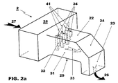
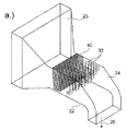
対応する装置を、図2aにおいて斜視図で示す。このような取入口ハウジング2は通常、広幅の吸入部分25を有し、この吸入部分25内に大気空気流27が流入する。この広幅吸入部分25より下流、または、広幅吸入部分25内部では、典型的には流れ断面が縮小され、この広幅吸入部分25の後には、流れ断面が一定である、典型的には水平方向の領域22が続く。この領域22の下流には、典型的には曲げ領域24が設けられており、空気流26が圧縮器1の取入口に入り込み、当該圧縮器1で圧縮することができるように、この曲げ領域24は空気流の方向を垂直方向に、取入口ハウジングの垂直方向領域23に変える。
A corresponding device is shown in perspective view in FIG. 2a. Such an intake housing 2 usually has a
本発明では、複数の指状部材の形態の混合ダクト32を領域22に配置する。これらの混合ダクト32は、領域22の側壁のうち1つから流路31内へ突出する。これらの混合ダクト32は側壁の1つに(または、いずれか複数の側壁に)取り付けられており、これらの混合ダクト32は、再循環される煙道ガス41を取り込むための取入口34が設けられた側壁に固定される。
In the present invention, a mixing
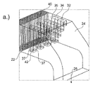
図2bに、上述のような混合ダクトの第1の実施形態を示す。この実施形態では、長方形または正方形の断面の管状部材の形態の3つの混合ダクト32が、相互に隣接して1列に配置されている。これら3つの混合ダクト32のうち、最上流に配置された混合ダクトが最も長い混合ダクトであり、よって、流路31内に最も大きく突出している。この最上流の混合ダクトはまた、列の前縁部35を成しており、後続の混合ダクトはこの前縁部35より下流の方向に配列されている。この1列において、最下流に配置された混合ダクトが最も短い混合ダクトとなって流路31内に最も小さく突出するように、かつ、基本的に、前記混合ダクト列の後縁部36を成すように、前記3つの混合ダクトの長さは規則的に短くなっていく。このようにして、前記混合ダクト列により、取入口34を介して取り込まれた煙道ガスを、矢印39で示されたように吹き出し、再循環される煙道ガスを空気流33の流れ断面全体にわたって分配するように導入する開口37が各混合ダクトの端部に設けられた構造が実現される。
FIG. 2b shows a first embodiment of a mixing duct as described above. In this embodiment, three mixing
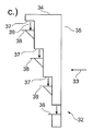
図2cに、上述の実施形態に代わる択一的な実施形態を示す。基本的に管状の混合ダクト32に底部壁が設けられていないので、底部に開口37が設けられている図2bの実施形態と異なり、図2cでは、管状部材32の底部は閉じられているが、各混合ダクトの各後縁側における各先端部分には排出開口37が設けられており、この排出開口37を通って煙道ガスが前記混合ダクトから、実質的に空気流の方向33に対して平行な方向に出ていく。
FIG. 2c shows an alternative embodiment to the above embodiment. Unlike the embodiment of FIG. 2b, in which the bottom wall of the tubular mixing
図3に、さらに別の実施形態の混合ダクト32を示す。この実施形態では、混合ダクトの列は設けられていないが、複数の吹出開口36を有する1つの混合ダクトが設けられており、これら複数の吹出開口36は、当該1つの混合ダクトの長さ全体にわたって分布されている。この1つの混合ダクトは階段状に形成されており、各段に、図2bに示された方向と同様の方向に空気流中に煙道ガスを吹き出す排出口37が設けられている。この実施形態では、各開口37のすぐ下流の空気流39が衝突板38に衝突する。この衝突板38は、空気流39の方向に対して実質的に垂直に、かつ、流路31内に流れる大気空気の空気流33に対して平行な方向に配置されている。これらの衝突板38は、混合ダクト32の後縁側壁に取り付けられている。上記実施形態の衝突板38は、混合ダクトの側壁から両側に横方向に突出しているが、衝突板38が側壁から突出しない構成も可能である。
FIG. 3 shows a mixing
広く言うと、図2に示されているように列を成して配置されているか、または、図3に示されているように長さにわたって分布された複数の開口37を有する構造を持つかに関わらず、前記混合ダクト32は板金部材から形成することができる。混合ダクト32を管状のパイプ形部材から形成することもできる。前縁部35における空気流33に対して可能な限り抵抗が小さくなるようにするためには、図3に示しているように、この前縁部35を丸めるのが有利であり、または、この前縁部は鋭角の前縁部を有することができる。有利には、表面が実質的に方向33に対して垂直である平坦な前縁部は避けるべきである。
Broadly speaking, is it arranged in a row as shown in FIG. 2 or has a structure with a plurality of
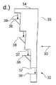
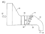
前縁部35は通常、図3cに示されているように、ダクトの軸に対して平行な方向に真っ直ぐである。しかし、流路31内の流れ環境に応じて、たとえば図3dに示されているように、前縁部35は成形された前縁部を有することも可能である。
The leading
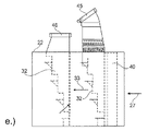
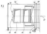
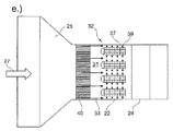
列を成すように配置される複数の混合ダクトは、図2aに示されたように、流れ方向33に対して垂直な方向に、相互に離隔されて列を成すように配置することができる。図3eに示されているように、上流混合ダクト32または上流混合ダクト列32と、下流混合ダクト32または下流混合ダクト列32とが設けられるように、複数の混合ダクトまたは複数の混合ダクト列を方向33に連続して配置することも可能である。これら各混合ダクトには、図3eに示されているように、各個別のダクト45および46によって、再循環された煙道ガスを供給するか、または、両列に結合された1つの同じダクトを用いて供給することができる。図3eおよび3fに示された実施形態では、2つの上流混合ダクト32が流路において、相互に横方向に大きな距離をおいて配置され、領域22の側壁に近接し、これら2つの上流混合ダクト32にはダクト45を介して煙道ガスが供給される。この混合ダクト対の下流には、第2群の混合ダクト32が設けられている。つまり、空気流方向33に対して垂直な方向に第2群の混合ダクト32が配置されており、これらは、前記2つの上流混合ダクト間のギャップを実質的に塞ぐように相互により近接する。
The plurality of mixing ducts arranged in rows can be arranged in rows spaced apart from each other in a direction perpendicular to the
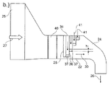
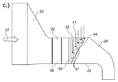
図4にさらに別の実施形態を示す。同図では、広幅吸入部分25より下流に、まず最初にサイレンサ40が配置されているのが分かる。また、このサイレンサと共に、またはこのサイレンサに代えて代替的にこの場所に、フィルタを設けることもできる。このフィルタは領域25内に配置することもできる。
FIG. 4 shows still another embodiment. In the figure, it can be seen that the
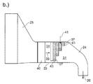
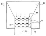
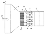
サイレンサ40より下流において、部分42内部に、横方向に配置された4列の混合ダクト32が配置されている。この構成でも各列は、下流方向に長さが規則的に短くなっていく4つの混合ダクトを有する。この実施形態では、各混合ダクトが末端位置において底部壁を有し、両側壁に側方開口37が設けられている。図4bに示されているように、煙道ガス41はこの側方開口37を通って、各混合ダクトの管状部分を通った後、図4cに示されているように、流れ方向33に対して垂直な方向に、実質的に水平方向に吹き出される。このことにより、図4cでは垂直方向に、図4dでは水平方向に、空気流33中に導入された煙道ガスは当該空気流33の流れ断面全体にわたって良好に分布されるが、図4dからも分かるように、流路の特定の長さにわたって混合導入が行われる。
Downstream from the
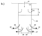
さらに別の実施形態を図5aに示す。この実施形態では、それぞれ4つの混合ダクトを有する、横方向に配置された4つの群を成すように配置された16個の混合ダクトは、基本的に図4と同じ構造となっている。しかしこの実施形態では、図4bに示されているように、高さhを有する、各混合ダクトの先端部分において各面に設けられた横方向の開口37に、丸められた案内翼42が設けられている。図5bに、この案内翼42の機能を最も良好に示す。これらの丸められた案内翼により、前記横方向の開口37の領域において混合ダクト32の通路を通る煙道ガス41が、前記横方向の開口37の底部領域においても頂部領域においても、高速かつ高圧で、良好に分配されてこれらの横方向の開口37を通って出て行けることが保証される。このことにより、混合装置における圧力損失が小さくなり、また、より均質な分布および混合が実現される。
Yet another embodiment is shown in FIG. In this embodiment, the 16 mixing ducts arranged to form four groups arranged in the lateral direction, each having four mixing ducts, have basically the same structure as that of FIG. However, in this embodiment, as shown in FIG. 4b, a
図6にも同様の実施形態を示すが、同図では案内翼は丸められておらず、各混合ダクトの主軸方向に対して実質的に垂直に配置された真っ直ぐな板として設けられている。 FIG. 6 shows a similar embodiment. In FIG. 6, the guide vanes are not rounded, and are provided as straight plates arranged substantially perpendicular to the main axis direction of each mixing duct.
これらの案内翼は典型的には、開口27自体の中に配置されるか、または当該開口27に非常に近接して配置されている。図5bに示されているように、有利には前記案内翼の高さは、開口37の全高hの実質的に半分の高さの所に来るように選択される。これに対応する案内翼の幅は有利には、混合ダクトの横方向の全幅の約1/4になるよう選択される。このことにより、空気流41の半分が案内翼によっていわば捉えられ、残り半分が案内翼の相互間を通過して、案内翼42/43の下に配置された開口37の部分を通って出て行けるようにすることができる。
These guide vanes are typically arranged in the
図7に、最後の実施形態を示す。この実施形態では、20個の混合ダクトが、それぞれ5つの混合ダクトを有する4つの群を成すように配置され、各混合ダクト群は三角形になっている。この三角形の群の後縁部は、斜めの後縁部壁44によって形成されている。このような後縁部壁により、三角形の開口37が実現され、このような後縁部壁は基本的に、図2bに示された構造と同様の構造に取り付けられる。このような開口37の構成は、図7bおよび7cを見ると良く分かる。このような三角形の横方向の開口により、煙道ガスの吹出がより一層良好に分布するようになり、この場合には、図7bおよび7cを見ると分かるように、混合ダクトの三角形の各列の長さは、流路の断面22を完全に横断するように調整されている。このような構成により、この流路断面において対向する両側壁に混合部材を取り付けることができ、ひいては、構成全体の安定性を上昇させることができる。
FIG. 7 shows the last embodiment. In this embodiment, 20 mixing ducts are arranged to form four groups each having five mixing ducts, and each mixing duct group is triangular. The rear edge of this group of triangles is formed by an oblique
1 圧縮器
2 取入口部分、取入口ハウジング
3 燃料供給部
4 第1の燃焼器
5 高圧タービン
6 第2の燃焼器
7 低圧タービン
8 排熱回収ボイラ
9 高圧蒸気タービン
10 中圧蒸気タービン
11 低圧蒸気タービン
12 復水器
13 ポンプ
14 スタックへ
15 ブロワ
16 質量流量測定装置
17 ダイバータ/ダンパ
18 煙道ガス再循環(FGR)システム
19 炭素捕捉システム
19a 二酸化炭素吸着ユニット
20 混合器
21 大気空気
21a 直接接触冷却器
22 2の水平方向部分
23 2の垂直方向部分
24 2の曲げ部分
25 2の広幅吸入部分
26 圧縮器の取入口における空気流
27 大気空気
28 22の側壁
29 22の底部壁
30 22の頂部壁
31 22内の流路
32 混合ダクト/混合指部
33 22内の空気流の方向
34 32の、煙道ガス再循環の取入口
35 32の前縁部
36 32の後縁部
37 32の排出口
38 衝突板
39 37における空気流および煙道ガス
40 サイレンサ
41 34および32内部における煙道ガスの流れ
42 丸みを有する案内翼
43 真っ直ぐな案内翼
44 斜めの後縁部壁
45 上流列へ煙道ガスを導入するためのダクト
46 下流列へ煙道ガスを導入するためのダクト
h 排出開口37の高さ
DESCRIPTION OF
Claims (14)
前記取入部(2)は、主要な空気流方向(33)に吸入空気の新鮮な空気流を流す流路(31)を有する少なくとも1つの領域(22)を含み、
前記流路(31)は、複数の側壁(28〜30)によって画定されており、
前記取入部(2)はさらに、少なくとも1つの前記側壁(28〜30)から前記流路(31)内に延在する少なくとも1つの混合ダクト(32)を有し、
前記混合ダクト(32)は、前記少なくとも1つの側壁(28〜30)に、再循環された煙道ガス(41)を取り込むための取入口(34)を有し、
前記取入部(2)はさらに、前記側壁(28〜30)から離隔されて設置された、再循環された煙道ガス(41)を前記混合ダクト(32)内部から前記空気流中へ吹き出すための少なくとも1つの排出開口(37)を有し、
少なくとも3つの前記混合ダクト(32)が列を成すように、相互に隣接して配置されており、
前記列の向きは実質的に、前記空気流方向(33)に沿うように配置されており、
最上流の前記混合ダクト(32)が前記列の前縁部を成し、
前記混合ダクト(32)が前記流路(31)内に延在する長さはすべて異なっており、
前記最上流の混合ダクト(32)が前記流路(31)内に最も大きく延在し、最下流の前記混合ダクト(32)が前記流路(31)内に最も小さく延在し、中間の前記混合ダクト(32)の長さは、下流における各混合ダクトの位置に応じて順次短くなっていく
ことを特徴とする取入部(2)。 An intake (2) installed upstream of the compressor (1) inlet of the gas turbine unit (1-7) for recirculating flue gas,
The intake (2) includes at least one region (22) having a flow path (31) for flowing a fresh air flow of intake air in a main air flow direction (33);
The flow path (31) is defined by a plurality of side walls (28-30),
The intake (2) further comprises at least one mixing duct (32) extending from the at least one side wall (28-30) into the flow path (31);
The mixing duct (32) has an intake (34) in the at least one side wall (28-30) for taking in recirculated flue gas (41);
The intake part (2) further blows out the recirculated flue gas (41) installed separately from the side walls (28-30) from the inside of the mixing duct (32) into the air stream. have at least one discharge opening (37) of,
At least three said mixing ducts (32) are arranged adjacent to each other in a row,
The orientation of the rows is arranged substantially along the air flow direction (33);
The most upstream mixing duct (32) forms the leading edge of the row;
The lengths of the mixing duct (32) extending into the flow path (31) are all different,
The most upstream mixing duct (32) extends the largest in the flow path (31), and the most downstream mixing duct (32) extends the smallest in the flow path (31). The intake section (2), wherein the length of the mixing duct (32) is sequentially reduced according to the position of each mixing duct downstream .
前記混合ダクト(32)の先端領域に少なくとも1つの排出開口(37)が配置されている、
請求項1記載の取入部(2)。 The mixing duct (32) is attached to only one of the side walls (22) and extends freely into the flow path (31),
At least one discharge opening (37) is arranged in the tip region of the mixing duct (32);
The intake part (2) according to claim 1.
および/または、
前記流路内において、少なくとも3つの前記列が、前記空気流方向(33)に沿って相互に離隔されて配置されている、
請求項1記載の取入部(2)。 In the flow path, at least three of the rows are spaced apart from each other along a direction perpendicular to the air flow direction (33),
And / or
In the flow path, at least three of the rows are arranged spaced apart from each other along the air flow direction (33).
The intake part (2) according to claim 1 .
請求項1から3までのいずれか1項記載の取入部(2)。 The at least one mixing duct (32) or the row of mixing ducts has the axis substantially perpendicular to the air flow direction (33) in the flow path (31) so that the flow path (31) Extending into the
The intake part (2) according to any one of claims 1 to 3 .
前記排出開口(37)は、前記空気流方向(33)に対して実質的に垂直な方向に開いているか、または、前記空気流方向(33)に対して実質的に平行かつ逆の方向に開いた構成である、
請求項1から4までのいずれか1項記載の取入部(2)。 Said mixing duct (32), have a four side walls defining the mixing duct,
The discharge opening (37) is open in a direction substantially perpendicular to the air flow direction (33) or in a direction substantially parallel and opposite to the air flow direction (33). Open configuration,
The intake part (2) according to any one of claims 1 to 4 .
請求項1から5までのいずれか1項記載の取入部(2)。 The at least one discharge opening (37) is configured to open in a direction substantially perpendicular to the air flow direction (33) and substantially perpendicular to the axis of the mixing duct (32). Yes ,
The intake part (2) according to any one of claims 1 to 5 .
請求項6記載の取入部(2)。 The at least one discharge opening (37) in or in the region of the at least one discharge opening (37), or straight at least one guide vane has a rounded (42, 43) are arranged,
The intake part (2) according to claim 6 .
前記煙道ガスが流れる方向で見て当該排出開口(37)の下流に混合エレメントが配置されている、
請求項1から5までのいずれか1項記載の取入部(2)。 The at least one discharge opening (37) is open in a direction substantially perpendicular to the air flow direction (33) and substantially parallel to the axis of the mixing duct (32). And
The mixture Ereme cement downstream of the flue gases as viewed in the direction of flow of the discharge opening (37) is placed,
The intake part (2) according to any one of claims 1 to 5 .
前記混合ダクト(32)または前記混合ダクトの列(32)の上流および/または下流において、サイレンサおよび/またはフィルタが前記領域(22)に配置されているか、または、当該領域(22)の実質的にすぐ上流および/またはすぐ下流に配置されている、
請求項1から8までのいずれか1項記載の取入部(2)。 The mixing duct (32) is arranged in a region (22) where the flow path (31) is defined by four side walls (28-30) arranged in parallel for each pair,
A silencer and / or a filter is arranged in the region (22) upstream of and / or downstream of the mixing duct (32) or the row of mixing ducts (32), or substantially in the region (22). Arranged immediately upstream and / or immediately downstream,
The intake part (2) according to any one of claims 1 to 8 .
請求項1から9までのいずれか1項記載の取入部(2)。 The mixing duct (32), or the mixing duct (32) arranged in the uppermost stream when a row having a plurality of mixing ducts (32) is provided, has a rounded leading edge.
The intake part (2) according to any one of claims 1 to 9 .
前記列の向きは、前記空気流方向(33)に実質的に沿うように配置されており、
最上流の前記混合ダクト(32)が、前記列の前縁部を成し、
前記混合ダクト(32)が前記流路(31)内に延在する長さはすべて異なっており、前記最上流の混合ダクト(32)が最も大きく前記流路(31)内に延在し、最下流の前記混合ダクト(32)は前記流路(31)内に最も小さく延在し、中間の前記混合ダクト(32)の長さは、下流における各混合ダクト(32)の配置位置に応じて順次かつ規則的に短くなっていき、
前記列の後縁部は、斜めになった後縁壁(44)によって形成されており、
前記列の各側壁において、前記空気流方向(33)に対して実質的に垂直でありかつ前記混合ダクト(32)の軸に対して実質的に垂直な方向に、3角形の排出開口(37)が開いた構成となっている、
請求項1から10までのいずれか1項記載の取入部(2)。 At least three said mixing ducts (32) are arranged adjacent to each other in a row,
The direction of the row is arranged so as to be substantially along the air flow direction (33),
The most upstream mixing duct (32) forms the leading edge of the row,
The lengths of the mixing duct (32) extending into the flow path (31) are all different, the uppermost mixing duct (32) is the largest and extends into the flow path (31), The most downstream mixing duct (32) extends the smallest in the flow path (31), and the length of the intermediate mixing duct (32) depends on the arrangement position of each mixing duct (32) downstream. Gradually and regularly shortened,
The trailing edge of the row is formed by a beveled trailing edge wall (44);
In each side wall of the row, a triangular discharge opening (37) in a direction substantially perpendicular to the air flow direction (33) and substantially perpendicular to the axis of the mixing duct (32). ) Is open,
The intake part (2) according to any one of claims 1 to 10 .
前記ガスタービンは、請求項1から11までのいずれか1項記載の取入部を有することを特徴とするガスタービン。 Cormorants line the flue gas recirculation, a gas turbine,
The gas turbine, gas turbine and having a intake portion of any one of claims 1 to 11.
請求項1から11までのいずれか1項記載の取入部を用いて、再循環された煙道ガスと新鮮な大気空気とを混合する
ことを特徴とする方法。 A method for recirculating flue gas to an inlet of a gas turbine unit ,
Method characterized by using the intake portion of any one of claims 1 to 11, mixing the recirculated flue gas and fresh ambient air.
前記流れ制御エレメントを使用して、再循環される煙道ガスの質量流量を制御する、
請求項13記載の方法。 Controlled based on mass flow measurement results in the recirculation path and / or based on measurement results of the composition of mixed intake air upstream of the compressor and / or based on combustion quality measurement results A flow control element is installed in the mixing duct (32) or upstream from the mixing duct;
Using the flow control element to control the mass flow rate of the recirculated flue gas;
The method of claim 13 .
Applications Claiming Priority (3)
| Application Number | Priority Date | Filing Date | Title |
|---|---|---|---|
| CH1152011 | 2011-01-24 | ||
| CH00115/11 | 2011-01-24 | ||
| PCT/EP2012/050964 WO2012101087A1 (en) | 2011-01-24 | 2012-01-23 | Mixing element for gas turbine units with flue gas recirculation |
Publications (2)
| Publication Number | Publication Date |
|---|---|
| JP2014505203A JP2014505203A (en) | 2014-02-27 |
| JP5788024B2 true JP5788024B2 (en) | 2015-09-30 |
Family
ID=43936485
Family Applications (1)
| Application Number | Title | Priority Date | Filing Date |
|---|---|---|---|
| JP2013550847A Expired - Fee Related JP5788024B2 (en) | 2011-01-24 | 2012-01-23 | Mixing element for gas turbine unit with flue gas recirculation |
Country Status (8)
| Country | Link |
|---|---|
| US (1) | US9453460B2 (en) |
| EP (1) | EP2668387B1 (en) |
| JP (1) | JP5788024B2 (en) |
| KR (1) | KR101574981B1 (en) |
| CN (1) | CN103328786B (en) |
| CA (1) | CA2824710C (en) |
| RU (1) | RU2573089C2 (en) |
| WO (1) | WO2012101087A1 (en) |
Families Citing this family (22)
| Publication number | Priority date | Publication date | Assignee | Title |
|---|---|---|---|---|
| EP2642097A1 (en) * | 2012-03-21 | 2013-09-25 | Alstom Technology Ltd | Method for operating a gas turbine and gas turbine for carrying out the method |
| US20130269358A1 (en) * | 2012-04-12 | 2013-10-17 | General Electric Company | Methods, systems and apparatus relating to reheat combustion turbine engines with exhaust gas recirculation |
| EP2837795B1 (en) * | 2013-08-14 | 2019-05-01 | Ansaldo Energia IP UK Limited | Improved intake arrangement in gas turbine power plant |
| EP2837794A1 (en) * | 2013-08-14 | 2015-02-18 | Alstom Technology Ltd | Improved intake arrangement in gas turbine power plant |
| KR101485020B1 (en) * | 2013-12-12 | 2015-01-29 | 연세대학교 산학협력단 | Super critical fluid gas cooling gas turbine device |
| WO2015147974A1 (en) * | 2014-03-26 | 2015-10-01 | Exxonmobil Upstream Research Company | System and method for the conditioning of recirculated exhaust gas |
| JP6522370B2 (en) * | 2015-02-26 | 2019-05-29 | 三菱日立パワーシステムズ株式会社 | Water discharge nozzle and mixing tank |
| RU2587511C1 (en) * | 2015-03-10 | 2016-06-20 | Публичное акционерное общество Научно-производственное объединение "Искра" | Air cleaning device |
| PL3344856T3 (en) | 2015-09-01 | 2020-11-02 | 8 Rivers Capital, Llc | Systems and methods for power production using nested co2 cycles |
| US10465714B2 (en) * | 2015-09-16 | 2019-11-05 | General Electric Company | Silencer duct having silencing element and couplers |
| US20170335734A1 (en) * | 2016-05-19 | 2017-11-23 | General Electric Company | Tempering Air System For Gas Turbine Selective Catalyst Reduction System |
| WO2019204394A2 (en) | 2018-04-17 | 2019-10-24 | Kayara Sammy | Wind-funneling for gas turbines |
| RU195474U1 (en) * | 2019-11-12 | 2020-01-29 | Ооо "Термокон" | HEATER-DRINKER |
| CN111058947B (en) * | 2020-01-09 | 2020-12-18 | 浙江特富发展股份有限公司 | Gas turbine exhaust utilization system |
| CN112007746A (en) * | 2020-08-14 | 2020-12-01 | 苏州西热节能环保技术有限公司 | Square primary air duct flow equalizing device at inlet of coal mill |
| RU2761711C1 (en) * | 2021-04-16 | 2021-12-13 | Общество с ограниченной ответственностью Самара-Авиагаз | Air-cleaning device |
| CN114688736B (en) * | 2022-03-21 | 2025-08-12 | 广东万和新电气股份有限公司 | Noise reduction device and gas water heater |
| US11859544B1 (en) * | 2022-06-16 | 2024-01-02 | Solar Turbines Incorporated | Turbine exhaust gas recirculation mixer box |
| CN115976456B (en) * | 2022-12-07 | 2024-09-27 | 镇江市博驰汽车配件有限公司 | Atmosphere circulation well type nitriding furnace and hydraulic motor output shaft nitriding process |
| IT202300003210A1 (en) | 2023-02-24 | 2024-08-24 | Nuovo Pignone Tecnologie Srl | SYSTEM AND METHOD FOR MIXING A RECIRCULATED EXHAUST GAS FLOW WITH AIR TO OBTAIN A GAS MIXTURE TO BE FEED TO A GAS TURBINE |
| KR102813394B1 (en) * | 2023-09-18 | 2025-05-27 | 현대제철 주식회사 | Combustion device for reducing nitrogen oxides |
| WO2025182185A1 (en) * | 2024-02-26 | 2025-09-04 | 三菱重工業株式会社 | Plant and plant control method |
Family Cites Families (23)
| Publication number | Priority date | Publication date | Assignee | Title |
|---|---|---|---|---|
| US4561245A (en) * | 1983-11-14 | 1985-12-31 | Atlantic Richfield Company | Turbine anti-icing system |
| SU1744290A1 (en) * | 1990-07-09 | 1992-06-30 | Казанский Авиационный Институт Им.А.Н.Туполева | Method of gas turbine plant operation |
| JP2548036Y2 (en) * | 1991-01-25 | 1997-09-17 | アイシン精機株式会社 | Exhaust gas recirculation device |
| DE19725668C1 (en) * | 1997-06-18 | 1998-10-29 | Daimler Benz Ag | Exhaust gas recirculation circuit for internal combustion engine |
| US6027305A (en) * | 1997-08-13 | 2000-02-22 | Virginia Tech Intellectual Properties, Inc. | Method and apparatus for reducing high-cycle fatigue and suppressing noise in rotating machinery |
| JP3716133B2 (en) * | 1999-07-07 | 2005-11-16 | 株式会社日立製作所 | Exhaust gas recirculation type gas turbine equipment and combined cycle power generation equipment equipped with the gas turbine equipment |
| DE19933030A1 (en) * | 1999-07-15 | 2001-01-18 | Mann & Hummel Filter | Fluid introduction for a hot fluid in a cavity structure |
| US6293265B1 (en) * | 1999-10-04 | 2001-09-25 | Siemens Canada Limited | Exhaust gas recirculation system |
| WO2004101975A1 (en) * | 2003-05-15 | 2004-11-25 | Alstom Technology Ltd | Device for damping sound in a duct |
| DE102004012080A1 (en) * | 2004-03-12 | 2005-10-13 | Alstom Technology Ltd | Apparatus and method for heating a gas stream |
| US7140357B2 (en) * | 2004-09-21 | 2006-11-28 | International Engine Intellectual Property Company, Llc | Vortex mixing system for exhaust gas recirculation (EGR) |
| US7028680B2 (en) * | 2004-09-21 | 2006-04-18 | International Engine Intellectual Property Company, Llc | Two stage mixing system for exhaust gas recirculation (EGR) |
| JP4989062B2 (en) * | 2005-04-28 | 2012-08-01 | バブコック日立株式会社 | Fluid mixing device |
| DE102005020484A1 (en) * | 2005-04-29 | 2006-11-02 | Mahle International Gmbh | Exhaust gas recirculation device for internal combustion engine, has exhaust gas recirculation valve for controlling exhaust gas recirculation line and comprising actuating device for axially adjusting sleeve relative to fresh-air duct |
| US8029234B2 (en) * | 2007-07-24 | 2011-10-04 | United Technologies Corp. | Systems and methods involving aerodynamic struts |
| US7770564B2 (en) * | 2007-10-31 | 2010-08-10 | Cummins, Inc. | Diffuser plate for improved mixing of EGR gas |
| US7730878B2 (en) * | 2007-12-26 | 2010-06-08 | Toyota Motor Engineering & Manufacturing North America, Inc. | Exhaust gas recirculation devices |
| US8448418B2 (en) * | 2008-03-11 | 2013-05-28 | General Electric Company | Method for controlling a flowrate of a recirculated exhaust gas |
| EP2246532A1 (en) * | 2008-12-24 | 2010-11-03 | Alstom Technology Ltd | Power plant with CO2 capture |
| EP2248999A1 (en) | 2008-12-24 | 2010-11-10 | Alstom Technology Ltd | Power plant with CO2 capture |
| CH701235A1 (en) * | 2009-06-09 | 2010-12-15 | Alstom Technology Ltd | Apparatus for mixing fresh intake air with recirculated exhaust air in a gas turbine. |
| CH701236A1 (en) * | 2009-06-09 | 2010-12-15 | Alstom Technology Ltd | Device for sound damping in a flow channel of a gas turbine having apparatus for supplying recirculated exhaust gases elements into the intake air. |
| US8317390B2 (en) * | 2010-02-03 | 2012-11-27 | Babcock & Wilcox Power Generation Group, Inc. | Stepped down gas mixing device |
-
2012
- 2012-01-23 RU RU2013139317/06A patent/RU2573089C2/en active
- 2012-01-23 CN CN201280006288.2A patent/CN103328786B/en active Active
- 2012-01-23 JP JP2013550847A patent/JP5788024B2/en not_active Expired - Fee Related
- 2012-01-23 CA CA2824710A patent/CA2824710C/en not_active Expired - Fee Related
- 2012-01-23 WO PCT/EP2012/050964 patent/WO2012101087A1/en not_active Ceased
- 2012-01-23 EP EP12700512.2A patent/EP2668387B1/en active Active
- 2012-01-23 KR KR1020137019111A patent/KR101574981B1/en not_active Expired - Fee Related
-
2013
- 2013-07-23 US US13/948,296 patent/US9453460B2/en active Active
Also Published As
| Publication number | Publication date |
|---|---|
| RU2573089C2 (en) | 2016-01-20 |
| CA2824710C (en) | 2016-09-06 |
| US9453460B2 (en) | 2016-09-27 |
| EP2668387B1 (en) | 2019-03-27 |
| US20130305732A1 (en) | 2013-11-21 |
| KR101574981B1 (en) | 2015-12-07 |
| CA2824710A1 (en) | 2012-08-02 |
| CN103328786B (en) | 2016-12-14 |
| CN103328786A (en) | 2013-09-25 |
| JP2014505203A (en) | 2014-02-27 |
| EP2668387A1 (en) | 2013-12-04 |
| RU2013139317A (en) | 2015-03-10 |
| KR20130140120A (en) | 2013-12-23 |
| WO2012101087A1 (en) | 2012-08-02 |
Similar Documents
| Publication | Publication Date | Title |
|---|---|---|
| JP5788024B2 (en) | Mixing element for gas turbine unit with flue gas recirculation | |
| US7861511B2 (en) | System for recirculating the exhaust of a turbomachine | |
| CN101725440B (en) | Inlet system for egr system | |
| JP6073458B2 (en) | Gas turbine power plant with heterogeneous input gas | |
| CN104428516B (en) | Gas turbine power device and its operation method with flue gas recirculation | |
| CN1245878A (en) | Boiler | |
| KR20160063272A (en) | Burner of a gas turbine | |
| CN101915429B (en) | Flue gas recirculation technology and combustor combustion air and circulating flue gas premixing device | |
| CN105992913A (en) | In-stream burner module | |
| US6929470B1 (en) | Low NOx duct burner | |
| US11761407B1 (en) | Inlet mixer for exhaust gas recirculation in power generation systems | |
| US20110146282A1 (en) | System and method for reducing sulfur compounds within fuel stream for turbomachine | |
| JP2001355832A (en) | Air port structure | |
| US20070125282A1 (en) | METHODS AND SYSTEMS FOR REDUCED NOx COMBUSTION OF COAL WITH INJECTION OF HEATED NITROGEN-CONTAINING GAS | |
| KR20250150120A (en) | System and method for mixing a recirculated exhaust gas stream with air to obtain a gas mixture to be fed to a gas turbine | |
| US20240019125A1 (en) | Method and device for recursive sequential combustion | |
| CN1099559C (en) | Multistage far-infrared radiation machine |
Legal Events
| Date | Code | Title | Description |
|---|---|---|---|
| A621 | Written request for application examination |
Free format text: JAPANESE INTERMEDIATE CODE: A621 Effective date: 20131225 |
|
| A131 | Notification of reasons for refusal |
Free format text: JAPANESE INTERMEDIATE CODE: A131 Effective date: 20141006 |
|
| A601 | Written request for extension of time |
Free format text: JAPANESE INTERMEDIATE CODE: A601 Effective date: 20150106 |
|
| A601 | Written request for extension of time |
Free format text: JAPANESE INTERMEDIATE CODE: A601 Effective date: 20150206 |
|
| A521 | Request for written amendment filed |
Free format text: JAPANESE INTERMEDIATE CODE: A523 Effective date: 20150302 |
|
| TRDD | Decision of grant or rejection written | ||
| A01 | Written decision to grant a patent or to grant a registration (utility model) |
Free format text: JAPANESE INTERMEDIATE CODE: A01 Effective date: 20150629 |
|
| A61 | First payment of annual fees (during grant procedure) |
Free format text: JAPANESE INTERMEDIATE CODE: A61 Effective date: 20150728 |
|
| R150 | Certificate of patent or registration of utility model |
Ref document number: 5788024 Country of ref document: JP Free format text: JAPANESE INTERMEDIATE CODE: R150 |
|
| S533 | Written request for registration of change of name |
Free format text: JAPANESE INTERMEDIATE CODE: R313533 |
|
| R350 | Written notification of registration of transfer |
Free format text: JAPANESE INTERMEDIATE CODE: R350 |
|
| S111 | Request for change of ownership or part of ownership |
Free format text: JAPANESE INTERMEDIATE CODE: R313113 |
|
| R350 | Written notification of registration of transfer |
Free format text: JAPANESE INTERMEDIATE CODE: R350 |
|
| LAPS | Cancellation because of no payment of annual fees |