JP5900564B2 - 熱交換器、空気調和機及び熱交換器の製造方法 - Google Patents
熱交換器、空気調和機及び熱交換器の製造方法 Download PDFInfo
- Publication number
- JP5900564B2 JP5900564B2 JP2014184537A JP2014184537A JP5900564B2 JP 5900564 B2 JP5900564 B2 JP 5900564B2 JP 2014184537 A JP2014184537 A JP 2014184537A JP 2014184537 A JP2014184537 A JP 2014184537A JP 5900564 B2 JP5900564 B2 JP 5900564B2
- Authority
- JP
- Japan
- Prior art keywords
- tube
- row
- flat tube
- leeward
- heat exchanger
- Prior art date
- Legal status (The legal status is an assumption and is not a legal conclusion. Google has not performed a legal analysis and makes no representation as to the accuracy of the status listed.)
- Active
Links
Images


Classifications
-
- F—MECHANICAL ENGINEERING; LIGHTING; HEATING; WEAPONS; BLASTING
- F28—HEAT EXCHANGE IN GENERAL
- F28F—DETAILS OF HEAT-EXCHANGE AND HEAT-TRANSFER APPARATUS, OF GENERAL APPLICATION
- F28F1/00—Tubular elements; Assemblies of tubular elements
- F28F1/10—Tubular elements and assemblies thereof with means for increasing heat-transfer area, e.g. with fins, with projections, with recesses
- F28F1/12—Tubular elements and assemblies thereof with means for increasing heat-transfer area, e.g. with fins, with projections, with recesses the means being only outside the tubular element
- F28F1/24—Tubular elements and assemblies thereof with means for increasing heat-transfer area, e.g. with fins, with projections, with recesses the means being only outside the tubular element and extending transversely
- F28F1/32—Tubular elements and assemblies thereof with means for increasing heat-transfer area, e.g. with fins, with projections, with recesses the means being only outside the tubular element and extending transversely the means having portions engaging further tubular elements
- F28F1/325—Fins with openings
-
- F—MECHANICAL ENGINEERING; LIGHTING; HEATING; WEAPONS; BLASTING
- F28—HEAT EXCHANGE IN GENERAL
- F28D—HEAT-EXCHANGE APPARATUS, NOT PROVIDED FOR IN ANOTHER SUBCLASS, IN WHICH THE HEAT-EXCHANGE MEDIA DO NOT COME INTO DIRECT CONTACT
- F28D1/00—Heat-exchange apparatus having stationary conduit assemblies for one heat-exchange medium only, the media being in contact with different sides of the conduit wall, in which the other heat-exchange medium is a large body of fluid, e.g. domestic or motor car radiators
- F28D1/02—Heat-exchange apparatus having stationary conduit assemblies for one heat-exchange medium only, the media being in contact with different sides of the conduit wall, in which the other heat-exchange medium is a large body of fluid, e.g. domestic or motor car radiators with heat-exchange conduits immersed in the body of fluid
- F28D1/04—Heat-exchange apparatus having stationary conduit assemblies for one heat-exchange medium only, the media being in contact with different sides of the conduit wall, in which the other heat-exchange medium is a large body of fluid, e.g. domestic or motor car radiators with heat-exchange conduits immersed in the body of fluid with tubular conduits
- F28D1/047—Heat-exchange apparatus having stationary conduit assemblies for one heat-exchange medium only, the media being in contact with different sides of the conduit wall, in which the other heat-exchange medium is a large body of fluid, e.g. domestic or motor car radiators with heat-exchange conduits immersed in the body of fluid with tubular conduits the conduits being bent, e.g. in a serpentine or zig-zag
- F28D1/0475—Heat-exchange apparatus having stationary conduit assemblies for one heat-exchange medium only, the media being in contact with different sides of the conduit wall, in which the other heat-exchange medium is a large body of fluid, e.g. domestic or motor car radiators with heat-exchange conduits immersed in the body of fluid with tubular conduits the conduits being bent, e.g. in a serpentine or zig-zag the conduits having a single U-bend
- F28D1/0476—Heat-exchange apparatus having stationary conduit assemblies for one heat-exchange medium only, the media being in contact with different sides of the conduit wall, in which the other heat-exchange medium is a large body of fluid, e.g. domestic or motor car radiators with heat-exchange conduits immersed in the body of fluid with tubular conduits the conduits being bent, e.g. in a serpentine or zig-zag the conduits having a single U-bend the conduits having a non-circular cross-section
-
- F—MECHANICAL ENGINEERING; LIGHTING; HEATING; WEAPONS; BLASTING
- F28—HEAT EXCHANGE IN GENERAL
- F28F—DETAILS OF HEAT-EXCHANGE AND HEAT-TRANSFER APPARATUS, OF GENERAL APPLICATION
- F28F1/00—Tubular elements; Assemblies of tubular elements
- F28F1/02—Tubular elements of cross-section which is non-circular
- F28F1/022—Tubular elements of cross-section which is non-circular with multiple channels
-
- F—MECHANICAL ENGINEERING; LIGHTING; HEATING; WEAPONS; BLASTING
- F28—HEAT EXCHANGE IN GENERAL
- F28F—DETAILS OF HEAT-EXCHANGE AND HEAT-TRANSFER APPARATUS, OF GENERAL APPLICATION
- F28F27/00—Control arrangements or safety devices specially adapted for heat-exchange or heat-transfer apparatus
- F28F27/02—Control arrangements or safety devices specially adapted for heat-exchange or heat-transfer apparatus for controlling the distribution of heat-exchange media between different channels
-
- F—MECHANICAL ENGINEERING; LIGHTING; HEATING; WEAPONS; BLASTING
- F28—HEAT EXCHANGE IN GENERAL
- F28F—DETAILS OF HEAT-EXCHANGE AND HEAT-TRANSFER APPARATUS, OF GENERAL APPLICATION
- F28F9/00—Casings; Header boxes; Auxiliary supports for elements; Auxiliary members within casings
- F28F9/02—Header boxes; End plates
- F28F9/0202—Header boxes having their inner space divided by partitions
- F28F9/0204—Header boxes having their inner space divided by partitions for elongated header box, e.g. with transversal and longitudinal partitions
-
- F—MECHANICAL ENGINEERING; LIGHTING; HEATING; WEAPONS; BLASTING
- F28—HEAT EXCHANGE IN GENERAL
- F28F—DETAILS OF HEAT-EXCHANGE AND HEAT-TRANSFER APPARATUS, OF GENERAL APPLICATION
- F28F9/00—Casings; Header boxes; Auxiliary supports for elements; Auxiliary members within casings
- F28F9/02—Header boxes; End plates
- F28F9/026—Header boxes; End plates with static flow control means, e.g. with means for uniformly distributing heat exchange media into conduits
- F28F9/0265—Header boxes; End plates with static flow control means, e.g. with means for uniformly distributing heat exchange media into conduits by using guiding means or impingement means inside the header box
-
- F—MECHANICAL ENGINEERING; LIGHTING; HEATING; WEAPONS; BLASTING
- F28—HEAT EXCHANGE IN GENERAL
- F28F—DETAILS OF HEAT-EXCHANGE AND HEAT-TRANSFER APPARATUS, OF GENERAL APPLICATION
- F28F9/00—Casings; Header boxes; Auxiliary supports for elements; Auxiliary members within casings
- F28F9/02—Header boxes; End plates
- F28F9/026—Header boxes; End plates with static flow control means, e.g. with means for uniformly distributing heat exchange media into conduits
- F28F9/0278—Header boxes; End plates with static flow control means, e.g. with means for uniformly distributing heat exchange media into conduits in the form of stacked distribution plates or perforated plates arranged over end plates
-
- F—MECHANICAL ENGINEERING; LIGHTING; HEATING; WEAPONS; BLASTING
- F28—HEAT EXCHANGE IN GENERAL
- F28F—DETAILS OF HEAT-EXCHANGE AND HEAT-TRANSFER APPARATUS, OF GENERAL APPLICATION
- F28F2275/00—Fastening; Joining
- F28F2275/04—Fastening; Joining by brazing
Landscapes
- Engineering & Computer Science (AREA)
- Physics & Mathematics (AREA)
- Thermal Sciences (AREA)
- Mechanical Engineering (AREA)
- General Engineering & Computer Science (AREA)
- Geometry (AREA)
- Heat-Exchange Devices With Radiators And Conduit Assemblies (AREA)
- Other Air-Conditioning Systems (AREA)
- Details Of Heat-Exchange And Heat-Transfer (AREA)
Description
空気調和機(10)について、図1を参照しながら説明する。
空気調和機(10)は、室外ユニット(11)および室内ユニット(12)を備えている。室外ユニット(11)と室内ユニット(12)は、液側連絡配管(13)およびガス側連絡配管(14)を介して互いに接続されている。空気調和機(10)では、室外ユニット(11)、室内ユニット(12)、液側連絡配管(13)およびガス側連絡配管(14)によって、冷媒回路(20)が形成されている。
空気調和機(10)は、冷房運転と暖房運転を選択的に行う。
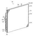
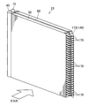
室外熱交換器(23)について、図2〜10を適宜参照しながら説明する。なお、以下の説明に示す扁平管(31,61)の本数は、単なる一例である。
詳しくは後述するが、風上熱交換器ユニット(30)は、図5,6に示すように上下に二つの領域に区分されている。そして、風上熱交換器ユニット(30)は、上側の領域が風上主熱交換領域(35)となり、下側の領域が風上補助熱交換領域(37)となっている。
詳しくは後述するが、風下熱交換器ユニット(60)は、図5,6に示すように上下に二つの熱交換領域(65,67)に区分されている。そして、風下熱交換器ユニット(60)は、上側の領域が風下主熱交換領域(65)となり、下側の領域が風下補助熱交換領域(67)となっている。
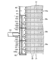
上述したように、風上ヘッダ集合管(40)のうち下側空間(43)を形成する部分は、分流器(150)を構成する。この分流器(150)は、室外熱交換器(23)が蒸発器として機能する場合に、室外熱交換器(23)へ供給された気液二相状態の冷媒を三つの風上補助熱交換部(38a〜38c)へ分配する。ここでは、分流器(150)について、図10を参照しながら説明する。
本実施形態の前提技術の2列構造の室外熱交換器(23)は、以下のようにして製造することができる。
本実施形態の前提技術によれば、二列構造の室外熱交換器(23)において、風上管列(50)側のフィン(32)の突出部(188)と風下管列(90)側のフィン(62)の突出部(188)が互いに向き合うように配置されている。上記突出部(188)は、複数の扁平管部(31,61)同士の間隔を保つためなどに形成されるものであるが、この突出部(188)が二列構造の室外熱交換器(23)の外面に露出していると、突出部(188)が周囲の機器との干渉により変形したり損傷したりするおそれがあるのに対して、本実施形態の前提技術では、突出部(188)が二列構造の室外熱交換器(23)の内側に位置しているので、突出部(188)が変形したり損傷したりするのを防止できる。
上記実施形態の前提技術については、以下のような構成としてもよい。
本実施形態では、上記前提技術において、上記風上管列(50)の扁平管である扁平管部(31)と風下管列(90)の扁平管である扁平管部(61)が、図15に示すように、両扁平管部(31,61)の扁平面に直交する方向(扁平管部(31,61)の配列方向)に位置をずらすように配置されている。いわゆる千鳥配置である。このようにすると、風上管列(50)の扁平管部(31)と扁平管部(31)の間を扁平管部(31)に接触せずに通過した空気が風下管列(90)の扁平管部(61)に接触する状態で通過するので、扁平管部(31,61)と接触しない風量が少なくなり、熱交換効率を高められる。
23 室外熱交換器
31 扁平管部
32 フィン
33 フィン群
50 風上管列
61 扁平管部
62 フィン
63 フィン群
90 風下管列
140 ギャップ部
170 扁平管
173 折り曲げ部(接続部材)
174 管継手(接続部材)
186 切り欠き部
187 管挿入部
188 突出部
Claims (4)
- 平行に並んだ複数の扁平管部(31,61)によってそれぞれが構成されて空気の流れ方向に並ぶ風上管列(50)及び風下管列(90)と、上記扁平管部(31,61)に接合されたフィン(32,62)とを備えた熱交換器(23)の製造方法であって、
一方の縁部に一定の間隔で形成された複数の切り欠き部(186)と、該切り欠き部(186)から他方の縁部に向かって形成され扁平管部(31,61)が挿入される管挿入部(187)とを有する上記フィン(32,62)を、風上管列(50)の扁平管部(31)と風下管列(90)の扁平管部(61)を有する複数の扁平管(170)それぞれの一端部と他端部に管挿入部(187)側の縁部を同じ向きにして装着するフィン装着工程と、
上記各扁平管(170)を一端部と他端部の間で折り曲げることにより、フィン(32,62)の管挿入部(187)側の縁部同士が向かい合う状態で風上管列(50)と風下管列(90)を形成する管列形成工程と、
を備え、
上記管列形成工程は、上記扁平管(170)を、風上管列(50)の扁平管部(31)と風下管列(90)の扁平管部(61)の位置が、両扁平管部(31,61)の扁平面に直交する方向にずれるように折り曲げる工程であることを特徴とする熱交換器の製造方法。 - 請求項1において、
上記フィン(32,62)が、上記一方の縁部に、隣り合う切り欠き部(186)の間に形成されて上記扁平管部(31,61)から突出する突出部(188)を有するフィンであり、
上記管列形成工程において、上記風上管列(50)側のフィン(32)の突出部(188)と風下管列(90)側のフィン(62)の突出部(188)とが互いに向かい合うように上記各扁平管(170)を一端部と他端部の間で折り曲げることを特徴とする熱交換器の製造方法。 - 請求項1または2において、
上記フィン装着工程では、扁平管部(31)の一端部と他端部に複数の上記フィン(32,62)を装着することにより風上管列(50)のフィン群(33)と風下管列のフィン群(63)を形成する一方、両フィン群(33,63)の間にはフィン(32,62)を装着しないギャップ部(140)を形成することを特徴とする熱交換器の製造方法。 - 請求項1から3のいずれか1つにおいて、
上記管列形成工程は、上記扁平管(170)を上記一端部と他端部の間でU字状に折り曲げる工程であって、U字状の折り曲げ部(173)を該扁平管(170)の平面から外れる立体的な折り曲げ部(173)にする工程であることを特徴とする熱交換器の製造方法。
Priority Applications (1)
| Application Number | Priority Date | Filing Date | Title |
|---|---|---|---|
| JP2014184537A JP5900564B2 (ja) | 2013-09-11 | 2014-09-10 | 熱交換器、空気調和機及び熱交換器の製造方法 |
Applications Claiming Priority (3)
| Application Number | Priority Date | Filing Date | Title |
|---|---|---|---|
| JP2013188526 | 2013-09-11 | ||
| JP2013188526 | 2013-09-11 | ||
| JP2014184537A JP5900564B2 (ja) | 2013-09-11 | 2014-09-10 | 熱交換器、空気調和機及び熱交換器の製造方法 |
Publications (2)
| Publication Number | Publication Date |
|---|---|
| JP2015078829A JP2015078829A (ja) | 2015-04-23 |
| JP5900564B2 true JP5900564B2 (ja) | 2016-04-06 |
Family
ID=52665366
Family Applications (1)
| Application Number | Title | Priority Date | Filing Date |
|---|---|---|---|
| JP2014184537A Active JP5900564B2 (ja) | 2013-09-11 | 2014-09-10 | 熱交換器、空気調和機及び熱交換器の製造方法 |
Country Status (3)
| Country | Link |
|---|---|
| JP (1) | JP5900564B2 (ja) |
| CN (1) | CN105518405A (ja) |
| WO (1) | WO2015037235A1 (ja) |
Cited By (1)
| Publication number | Priority date | Publication date | Assignee | Title |
|---|---|---|---|---|
| CN110476026A (zh) * | 2017-03-27 | 2019-11-19 | 大金工业株式会社 | 热交换器单元 |
Families Citing this family (12)
| Publication number | Priority date | Publication date | Assignee | Title |
|---|---|---|---|---|
| JP6583729B2 (ja) * | 2015-11-24 | 2019-10-02 | 株式会社富士通ゼネラル | 熱交換器 |
| USD787033S1 (en) * | 2015-12-24 | 2017-05-16 | Danfoss Micro Channel Heat Exchanger (Jiaxing) Co., Ltd. | Heat exchanger |
| JP2017133790A (ja) * | 2016-01-29 | 2017-08-03 | 株式会社富士通ゼネラル | 熱交換器 |
| US11415371B2 (en) | 2017-03-27 | 2022-08-16 | Daikin Industries, Ltd. | Heat exchanger and refrigeration apparatus |
| CN110686429B (zh) * | 2018-07-04 | 2024-11-08 | 浙江盾安热工科技有限公司 | 微通道换热器 |
| SG11202012777WA (en) | 2018-10-18 | 2021-05-28 | Carrier Corp | Microchannel heat exchanger tube supported bracket |
| CN110986632B (zh) * | 2019-12-05 | 2025-04-01 | 博格思众(常州)热交换器有限公司 | 微通道平行流换热器 |
| US12460872B2 (en) | 2020-08-31 | 2025-11-04 | Sanhua (Hangzhou) Micro Channel Heat Exchanger Co., Ltd. | Heat exchanger and method for processing heat exchanger |
| US12546538B2 (en) | 2020-11-25 | 2026-02-10 | Carrier Corporation | Microchannel heat exchanger tube supported bracket |
| JP2022185368A (ja) * | 2021-06-02 | 2022-12-14 | パナソニックIpマネジメント株式会社 | ヒートポンプシステム |
| CN115451748A (zh) * | 2021-06-09 | 2022-12-09 | 浙江盾安热工科技有限公司 | 扁管及换热器 |
| WO2023036279A1 (zh) * | 2021-09-13 | 2023-03-16 | 浙江盾安人工环境股份有限公司 | 换热器及微通道换热器 |
Family Cites Families (18)
| Publication number | Priority date | Publication date | Assignee | Title |
|---|---|---|---|---|
| FR1050082A (fr) * | 1952-02-01 | 1954-01-05 | Radiateur de chauffage | |
| JPS63154962U (ja) * | 1987-03-30 | 1988-10-12 | ||
| JP2624336B2 (ja) * | 1989-06-28 | 1997-06-25 | 松下冷機株式会社 | フィン付熱交換器 |
| JP3305460B2 (ja) * | 1993-11-24 | 2002-07-22 | 昭和電工株式会社 | 熱交換器 |
| JP2851540B2 (ja) * | 1994-11-17 | 1999-01-27 | 昭和アルミニウム株式会社 | 熱交換器 |
| US6964296B2 (en) * | 2001-02-07 | 2005-11-15 | Modine Manufacturing Company | Heat exchanger |
| CN100513977C (zh) * | 2005-12-07 | 2009-07-15 | 松下电器产业株式会社 | 热交换器 |
| JP2007170718A (ja) * | 2005-12-20 | 2007-07-05 | Denso Corp | 熱交換器 |
| JP2007192441A (ja) * | 2006-01-18 | 2007-08-02 | Matsushita Electric Ind Co Ltd | 放熱器、放熱器の製造方法及びそれを備えた冷却装置 |
| JP2007192474A (ja) * | 2006-01-19 | 2007-08-02 | Calsonic Kansei Corp | 熱交換器 |
| DE102006018688B4 (de) * | 2006-04-13 | 2009-08-27 | Visteon Global Technologies Inc., Van Buren | Verfahren zum Biegen von Multiportrohren für Wärmeübertrager |
| JP4989979B2 (ja) * | 2007-01-10 | 2012-08-01 | 昭和電工株式会社 | 熱交換器 |
| JP2009216315A (ja) * | 2008-03-11 | 2009-09-24 | Showa Denko Kk | 熱交換器 |
| JP5084707B2 (ja) * | 2008-12-11 | 2012-11-28 | 三菱電機株式会社 | 空気調和機 |
| JP5335568B2 (ja) * | 2009-06-12 | 2013-11-06 | 三菱電機株式会社 | 扁平管熱交換器 |
| JP2011112315A (ja) * | 2009-11-30 | 2011-06-09 | Mitsubishi Electric Corp | フィンチューブ型熱交換器及びこれを用いた空気調和機 |
| CN201652995U (zh) * | 2010-05-20 | 2010-11-24 | 三花丹佛斯(杭州)微通道换热器有限公司 | 微通道换热器 |
| US9551540B2 (en) * | 2011-11-22 | 2017-01-24 | Daikin Industries, Ltd. | Heat exchanger |
-
2014
- 2014-09-10 WO PCT/JP2014/004668 patent/WO2015037235A1/ja not_active Ceased
- 2014-09-10 CN CN201480048597.5A patent/CN105518405A/zh active Pending
- 2014-09-10 JP JP2014184537A patent/JP5900564B2/ja active Active
Cited By (2)
| Publication number | Priority date | Publication date | Assignee | Title |
|---|---|---|---|---|
| CN110476026A (zh) * | 2017-03-27 | 2019-11-19 | 大金工业株式会社 | 热交换器单元 |
| CN110476026B (zh) * | 2017-03-27 | 2021-08-10 | 大金工业株式会社 | 热交换器单元 |
Also Published As
| Publication number | Publication date |
|---|---|
| WO2015037235A1 (ja) | 2015-03-19 |
| JP2015078829A (ja) | 2015-04-23 |
| CN105518405A (zh) | 2016-04-20 |
Similar Documents
| Publication | Publication Date | Title |
|---|---|---|
| JP5900564B2 (ja) | 熱交換器、空気調和機及び熱交換器の製造方法 | |
| CN204085299U (zh) | 热交换器及空调机 | |
| JP5679084B1 (ja) | 熱交換器および空気調和機 | |
| CN105473977B (zh) | 热交换器及空调机 | |
| CN105518411B (zh) | 热交换器及空调机 | |
| JP2015078833A5 (ja) | ||
| JP5900440B2 (ja) | 熱交換器の製造方法及び熱交換器 | |
| JP2016205743A (ja) | 熱交換器及び空気調和機 | |
| JP5716496B2 (ja) | 熱交換器および空気調和機 | |
| JP2015055413A (ja) | 熱交換器 | |
| JP2015055408A (ja) | 熱交換器及び空気調和機 | |
| JP2015055398A (ja) | 熱交換器のロウ付け方法 | |
| JP6171766B2 (ja) | 熱交換器 | |
| JP2020148346A (ja) | 熱交換器及び空気調和機 | |
| JP6171765B2 (ja) | 熱交換器 | |
| JP2015055414A (ja) | 熱交換器 | |
| JP2015055407A (ja) | 熱交換器及び空気調和機 | |
| JP2015055409A (ja) | 熱交換器および空気調和機 | |
| JP2015055400A (ja) | 熱交換器 |
Legal Events
| Date | Code | Title | Description |
|---|---|---|---|
| A521 | Written amendment |
Free format text: JAPANESE INTERMEDIATE CODE: A523 Effective date: 20150209 |
|
| A131 | Notification of reasons for refusal |
Free format text: JAPANESE INTERMEDIATE CODE: A131 Effective date: 20150714 |
|
| A521 | Written amendment |
Free format text: JAPANESE INTERMEDIATE CODE: A523 Effective date: 20150901 |
|
| TRDD | Decision of grant or rejection written | ||
| A01 | Written decision to grant a patent or to grant a registration (utility model) |
Free format text: JAPANESE INTERMEDIATE CODE: A01 Effective date: 20160209 |
|
| A61 | First payment of annual fees (during grant procedure) |
Free format text: JAPANESE INTERMEDIATE CODE: A61 Effective date: 20160222 |
|
| R151 | Written notification of patent or utility model registration |
Ref document number: 5900564 Country of ref document: JP Free format text: JAPANESE INTERMEDIATE CODE: R151 |