JP6242592B2 - Method for operating a solar installation - Google Patents
Method for operating a solar installation Download PDFInfo
- Publication number
- JP6242592B2 JP6242592B2 JP2013113790A JP2013113790A JP6242592B2 JP 6242592 B2 JP6242592 B2 JP 6242592B2 JP 2013113790 A JP2013113790 A JP 2013113790A JP 2013113790 A JP2013113790 A JP 2013113790A JP 6242592 B2 JP6242592 B2 JP 6242592B2
- Authority
- JP
- Japan
- Prior art keywords
- live steam
- valve
- turbine
- reference value
- actual value
- Prior art date
- Legal status (The legal status is an assumption and is not a legal conclusion. Google has not performed a legal analysis and makes no representation as to the accuracy of the status listed.)
- Expired - Fee Related
Links
Images

Classifications
-
- F—MECHANICAL ENGINEERING; LIGHTING; HEATING; WEAPONS; BLASTING
- F01—MACHINES OR ENGINES IN GENERAL; ENGINE PLANTS IN GENERAL; STEAM ENGINES
- F01K—STEAM ENGINE PLANTS; STEAM ACCUMULATORS; ENGINE PLANTS NOT OTHERWISE PROVIDED FOR; ENGINES USING SPECIAL WORKING FLUIDS OR CYCLES
- F01K13/00—General layout or general methods of operation of complete plants
- F01K13/02—Controlling, e.g. stopping or starting
-
- F—MECHANICAL ENGINEERING; LIGHTING; HEATING; WEAPONS; BLASTING
- F01—MACHINES OR ENGINES IN GENERAL; ENGINE PLANTS IN GENERAL; STEAM ENGINES
- F01D—NON-POSITIVE DISPLACEMENT MACHINES OR ENGINES, e.g. STEAM TURBINES
- F01D11/00—Preventing or minimising internal leakage of working-fluid, e.g. between stages
- F01D11/02—Preventing or minimising internal leakage of working-fluid, e.g. between stages by non-contact sealings, e.g. of labyrinth type
- F01D11/04—Preventing or minimising internal leakage of working-fluid, e.g. between stages by non-contact sealings, e.g. of labyrinth type using sealing fluid, e.g. steam
-
- F—MECHANICAL ENGINEERING; LIGHTING; HEATING; WEAPONS; BLASTING
- F01—MACHINES OR ENGINES IN GENERAL; ENGINE PLANTS IN GENERAL; STEAM ENGINES
- F01D—NON-POSITIVE DISPLACEMENT MACHINES OR ENGINES, e.g. STEAM TURBINES
- F01D11/00—Preventing or minimising internal leakage of working-fluid, e.g. between stages
- F01D11/02—Preventing or minimising internal leakage of working-fluid, e.g. between stages by non-contact sealings, e.g. of labyrinth type
- F01D11/04—Preventing or minimising internal leakage of working-fluid, e.g. between stages by non-contact sealings, e.g. of labyrinth type using sealing fluid, e.g. steam
- F01D11/06—Control thereof
-
- F—MECHANICAL ENGINEERING; LIGHTING; HEATING; WEAPONS; BLASTING
- F01—MACHINES OR ENGINES IN GENERAL; ENGINE PLANTS IN GENERAL; STEAM ENGINES
- F01D—NON-POSITIVE DISPLACEMENT MACHINES OR ENGINES, e.g. STEAM TURBINES
- F01D19/00—Starting of machines or engines; Regulating, controlling, or safety means in connection therewith
-
- F—MECHANICAL ENGINEERING; LIGHTING; HEATING; WEAPONS; BLASTING
- F01—MACHINES OR ENGINES IN GENERAL; ENGINE PLANTS IN GENERAL; STEAM ENGINES
- F01D—NON-POSITIVE DISPLACEMENT MACHINES OR ENGINES, e.g. STEAM TURBINES
- F01D19/00—Starting of machines or engines; Regulating, controlling, or safety means in connection therewith
- F01D19/02—Starting of machines or engines; Regulating, controlling, or safety means in connection therewith dependent on temperature of component parts, e.g. of turbine-casing
-
- F—MECHANICAL ENGINEERING; LIGHTING; HEATING; WEAPONS; BLASTING
- F01—MACHINES OR ENGINES IN GENERAL; ENGINE PLANTS IN GENERAL; STEAM ENGINES
- F01D—NON-POSITIVE DISPLACEMENT MACHINES OR ENGINES, e.g. STEAM TURBINES
- F01D25/00—Component parts, details, or accessories, not provided for in, or of interest apart from, other groups
- F01D25/08—Cooling; Heating; Heat-insulation
-
- F—MECHANICAL ENGINEERING; LIGHTING; HEATING; WEAPONS; BLASTING
- F01—MACHINES OR ENGINES IN GENERAL; ENGINE PLANTS IN GENERAL; STEAM ENGINES
- F01D—NON-POSITIVE DISPLACEMENT MACHINES OR ENGINES, e.g. STEAM TURBINES
- F01D25/00—Component parts, details, or accessories, not provided for in, or of interest apart from, other groups
- F01D25/08—Cooling; Heating; Heat-insulation
- F01D25/10—Heating, e.g. warming-up before starting
-
- F—MECHANICAL ENGINEERING; LIGHTING; HEATING; WEAPONS; BLASTING
- F01—MACHINES OR ENGINES IN GENERAL; ENGINE PLANTS IN GENERAL; STEAM ENGINES
- F01D—NON-POSITIVE DISPLACEMENT MACHINES OR ENGINES, e.g. STEAM TURBINES
- F01D25/00—Component parts, details, or accessories, not provided for in, or of interest apart from, other groups
- F01D25/18—Lubricating arrangements
- F01D25/22—Lubricating arrangements using working-fluid or other gaseous fluid as lubricant
-
- F—MECHANICAL ENGINEERING; LIGHTING; HEATING; WEAPONS; BLASTING
- F01—MACHINES OR ENGINES IN GENERAL; ENGINE PLANTS IN GENERAL; STEAM ENGINES
- F01K—STEAM ENGINE PLANTS; STEAM ACCUMULATORS; ENGINE PLANTS NOT OTHERWISE PROVIDED FOR; ENGINES USING SPECIAL WORKING FLUIDS OR CYCLES
- F01K17/00—Using steam or condensate extracted or exhausted from steam engine plant
- F01K17/04—Using steam or condensate extracted or exhausted from steam engine plant for specific purposes other than heating
-
- F—MECHANICAL ENGINEERING; LIGHTING; HEATING; WEAPONS; BLASTING
- F01—MACHINES OR ENGINES IN GENERAL; ENGINE PLANTS IN GENERAL; STEAM ENGINES
- F01K—STEAM ENGINE PLANTS; STEAM ACCUMULATORS; ENGINE PLANTS NOT OTHERWISE PROVIDED FOR; ENGINES USING SPECIAL WORKING FLUIDS OR CYCLES
- F01K25/00—Plants or engines characterised by use of special working fluids, not otherwise provided for; Plants operating in closed cycles and not otherwise provided for
- F01K25/08—Plants or engines characterised by use of special working fluids, not otherwise provided for; Plants operating in closed cycles and not otherwise provided for using special vapours
-
- F—MECHANICAL ENGINEERING; LIGHTING; HEATING; WEAPONS; BLASTING
- F01—MACHINES OR ENGINES IN GENERAL; ENGINE PLANTS IN GENERAL; STEAM ENGINES
- F01K—STEAM ENGINE PLANTS; STEAM ACCUMULATORS; ENGINE PLANTS NOT OTHERWISE PROVIDED FOR; ENGINES USING SPECIAL WORKING FLUIDS OR CYCLES
- F01K3/00—Plants characterised by the use of steam or heat accumulators, or intermediate steam heaters, therein
- F01K3/18—Plants characterised by the use of steam or heat accumulators, or intermediate steam heaters, therein having heaters
- F01K3/20—Plants characterised by the use of steam or heat accumulators, or intermediate steam heaters, therein having heaters with heating by combustion gases of main boiler
- F01K3/22—Controlling, e.g. starting, stopping
-
- F—MECHANICAL ENGINEERING; LIGHTING; HEATING; WEAPONS; BLASTING
- F01—MACHINES OR ENGINES IN GENERAL; ENGINE PLANTS IN GENERAL; STEAM ENGINES
- F01K—STEAM ENGINE PLANTS; STEAM ACCUMULATORS; ENGINE PLANTS NOT OTHERWISE PROVIDED FOR; ENGINES USING SPECIAL WORKING FLUIDS OR CYCLES
- F01K7/00—Steam engine plants characterised by the use of specific types of engine; Plants or engines characterised by their use of special steam systems, cycles or processes; Control means specially adapted for such systems, cycles or processes; Use of withdrawn or exhaust steam for feed-water heating
- F01K7/16—Steam engine plants characterised by the use of specific types of engine; Plants or engines characterised by their use of special steam systems, cycles or processes; Control means specially adapted for such systems, cycles or processes; Use of withdrawn or exhaust steam for feed-water heating the engines being only of turbine type
- F01K7/22—Steam engine plants characterised by the use of specific types of engine; Plants or engines characterised by their use of special steam systems, cycles or processes; Control means specially adapted for such systems, cycles or processes; Use of withdrawn or exhaust steam for feed-water heating the engines being only of turbine type the turbines having inter-stage steam heating
-
- F—MECHANICAL ENGINEERING; LIGHTING; HEATING; WEAPONS; BLASTING
- F01—MACHINES OR ENGINES IN GENERAL; ENGINE PLANTS IN GENERAL; STEAM ENGINES
- F01K—STEAM ENGINE PLANTS; STEAM ACCUMULATORS; ENGINE PLANTS NOT OTHERWISE PROVIDED FOR; ENGINES USING SPECIAL WORKING FLUIDS OR CYCLES
- F01K7/00—Steam engine plants characterised by the use of specific types of engine; Plants or engines characterised by their use of special steam systems, cycles or processes; Control means specially adapted for such systems, cycles or processes; Use of withdrawn or exhaust steam for feed-water heating
- F01K7/16—Steam engine plants characterised by the use of specific types of engine; Plants or engines characterised by their use of special steam systems, cycles or processes; Control means specially adapted for such systems, cycles or processes; Use of withdrawn or exhaust steam for feed-water heating the engines being only of turbine type
- F01K7/22—Steam engine plants characterised by the use of specific types of engine; Plants or engines characterised by their use of special steam systems, cycles or processes; Control means specially adapted for such systems, cycles or processes; Use of withdrawn or exhaust steam for feed-water heating the engines being only of turbine type the turbines having inter-stage steam heating
- F01K7/24—Control or safety means specially adapted therefor
-
- F—MECHANICAL ENGINEERING; LIGHTING; HEATING; WEAPONS; BLASTING
- F01—MACHINES OR ENGINES IN GENERAL; ENGINE PLANTS IN GENERAL; STEAM ENGINES
- F01K—STEAM ENGINE PLANTS; STEAM ACCUMULATORS; ENGINE PLANTS NOT OTHERWISE PROVIDED FOR; ENGINES USING SPECIAL WORKING FLUIDS OR CYCLES
- F01K7/00—Steam engine plants characterised by the use of specific types of engine; Plants or engines characterised by their use of special steam systems, cycles or processes; Control means specially adapted for such systems, cycles or processes; Use of withdrawn or exhaust steam for feed-water heating
- F01K7/34—Steam engine plants characterised by the use of specific types of engine; Plants or engines characterised by their use of special steam systems, cycles or processes; Control means specially adapted for such systems, cycles or processes; Use of withdrawn or exhaust steam for feed-water heating the engines being of extraction or non-condensing type; Use of steam for feed-water heating
- F01K7/40—Use of two or more feed-water heaters in series
-
- F—MECHANICAL ENGINEERING; LIGHTING; HEATING; WEAPONS; BLASTING
- F03—MACHINES OR ENGINES FOR LIQUIDS; WIND, SPRING, OR WEIGHT MOTORS; PRODUCING MECHANICAL POWER OR A REACTIVE PROPULSIVE THRUST, NOT OTHERWISE PROVIDED FOR
- F03G—SPRING, WEIGHT, INERTIA OR LIKE MOTORS; MECHANICAL-POWER PRODUCING DEVICES OR MECHANISMS, NOT OTHERWISE PROVIDED FOR OR USING ENERGY SOURCES NOT OTHERWISE PROVIDED FOR
- F03G6/00—Devices for producing mechanical power from solar energy
- F03G6/06—Devices for producing mechanical power from solar energy with solar energy concentrating means
- F03G6/065—Devices for producing mechanical power from solar energy with solar energy concentrating means having a Rankine cycle
-
- F—MECHANICAL ENGINEERING; LIGHTING; HEATING; WEAPONS; BLASTING
- F22—STEAM GENERATION
- F22B—METHODS OF STEAM GENERATION; STEAM BOILERS
- F22B1/00—Methods of steam generation characterised by form of heating method
- F22B1/006—Methods of steam generation characterised by form of heating method using solar heat
-
- F—MECHANICAL ENGINEERING; LIGHTING; HEATING; WEAPONS; BLASTING
- F22—STEAM GENERATION
- F22B—METHODS OF STEAM GENERATION; STEAM BOILERS
- F22B35/00—Control systems for steam boilers
- F22B35/06—Control systems for steam boilers for steam boilers of forced-flow type
- F22B35/14—Control systems for steam boilers for steam boilers of forced-flow type during the starting-up periods, i.e. during the periods between the lighting of the furnaces and the attainment of the normal operating temperature of the steam boilers
-
- F—MECHANICAL ENGINEERING; LIGHTING; HEATING; WEAPONS; BLASTING
- F24—HEATING; RANGES; VENTILATING
- F24S—SOLAR HEAT COLLECTORS; SOLAR HEAT SYSTEMS
- F24S20/00—Solar heat collectors specially adapted for particular uses or environments
- F24S20/20—Solar heat collectors for receiving concentrated solar energy, e.g. receivers for solar power plants
-
- G—PHYSICS
- G01—MEASURING; TESTING
- G01F—MEASURING VOLUME, VOLUME FLOW, MASS FLOW OR LIQUID LEVEL; METERING BY VOLUME
- G01F1/00—Measuring the volume flow or mass flow of fluid or fluent solid material wherein the fluid passes through a meter in a continuous flow
- G01F1/76—Devices for measuring mass flow of a fluid or a fluent solid material
- G01F1/86—Indirect mass flowmeters, e.g. measuring volume flow and density, temperature or pressure
- G01F1/90—Indirect mass flowmeters, e.g. measuring volume flow and density, temperature or pressure with positive-displacement meter or turbine meter to determine the volume flow
-
- Y—GENERAL TAGGING OF NEW TECHNOLOGICAL DEVELOPMENTS; GENERAL TAGGING OF CROSS-SECTIONAL TECHNOLOGIES SPANNING OVER SEVERAL SECTIONS OF THE IPC; TECHNICAL SUBJECTS COVERED BY FORMER USPC CROSS-REFERENCE ART COLLECTIONS [XRACs] AND DIGESTS
- Y02—TECHNOLOGIES OR APPLICATIONS FOR MITIGATION OR ADAPTATION AGAINST CLIMATE CHANGE
- Y02E—REDUCTION OF GREENHOUSE GAS [GHG] EMISSIONS, RELATED TO ENERGY GENERATION, TRANSMISSION OR DISTRIBUTION
- Y02E10/00—Energy generation through renewable energy sources
- Y02E10/40—Solar thermal energy, e.g. solar towers
- Y02E10/46—Conversion of thermal power into mechanical power, e.g. Rankine, Stirling or solar thermal engines
-
- Y—GENERAL TAGGING OF NEW TECHNOLOGICAL DEVELOPMENTS; GENERAL TAGGING OF CROSS-SECTIONAL TECHNOLOGIES SPANNING OVER SEVERAL SECTIONS OF THE IPC; TECHNICAL SUBJECTS COVERED BY FORMER USPC CROSS-REFERENCE ART COLLECTIONS [XRACs] AND DIGESTS
- Y02—TECHNOLOGIES OR APPLICATIONS FOR MITIGATION OR ADAPTATION AGAINST CLIMATE CHANGE
- Y02E—REDUCTION OF GREENHOUSE GAS [GHG] EMISSIONS, RELATED TO ENERGY GENERATION, TRANSMISSION OR DISTRIBUTION
- Y02E20/00—Combustion technologies with mitigation potential
- Y02E20/16—Combined cycle power plant [CCPP], or combined cycle gas turbine [CCGT]
-
- Y—GENERAL TAGGING OF NEW TECHNOLOGICAL DEVELOPMENTS; GENERAL TAGGING OF CROSS-SECTIONAL TECHNOLOGIES SPANNING OVER SEVERAL SECTIONS OF THE IPC; TECHNICAL SUBJECTS COVERED BY FORMER USPC CROSS-REFERENCE ART COLLECTIONS [XRACs] AND DIGESTS
- Y02—TECHNOLOGIES OR APPLICATIONS FOR MITIGATION OR ADAPTATION AGAINST CLIMATE CHANGE
- Y02E—REDUCTION OF GREENHOUSE GAS [GHG] EMISSIONS, RELATED TO ENERGY GENERATION, TRANSMISSION OR DISTRIBUTION
- Y02E20/00—Combustion technologies with mitigation potential
- Y02E20/16—Combined cycle power plant [CCPP], or combined cycle gas turbine [CCGT]
- Y02E20/18—Integrated gasification combined cycle [IGCC], e.g. combined with carbon capture and storage [CCS]
Landscapes
- Engineering & Computer Science (AREA)
- General Engineering & Computer Science (AREA)
- Mechanical Engineering (AREA)
- Combustion & Propulsion (AREA)
- Chemical & Material Sciences (AREA)
- Sustainable Energy (AREA)
- Life Sciences & Earth Sciences (AREA)
- Sustainable Development (AREA)
- Physics & Mathematics (AREA)
- Thermal Sciences (AREA)
- Fluid Mechanics (AREA)
- General Physics & Mathematics (AREA)
- Engine Equipment That Uses Special Cycles (AREA)
- Control Of Turbines (AREA)
Description
本発明は、請求項1のプレアンブルに記載のソーラー設備を作動させるための方法に関する。 The present invention relates to a method for operating a solar installation according to the preamble of claim 1.
ソーラー設備においては、電気エネルギーがソーラーエネルギーから発生させられる。このために、作動媒体、特に水が、ソーラー設備のソーラーフィールド内で蒸発させられ、そして蒸発させられた作動媒体はタービンに供給される。作動媒体はタービン内で膨張させられ、そして、こうして得られたエネルギーはソーラー設備の発電機を駆動するために使用される。発電機は電気エネルギーを発生させる。ソーラーフィールド内で発生させられ、タービンへと供給される作動媒体の蒸気はまた、生蒸気として知られている。 In solar installations, electrical energy is generated from solar energy. For this purpose, a working medium, in particular water, is evaporated in the solar field of the solar installation and the evaporated working medium is supplied to the turbine. The working medium is expanded in the turbine, and the energy thus obtained is used to drive the generator of the solar installation. A generator generates electrical energy. The working medium steam generated in the solar field and fed to the turbine is also known as live steam.
本発明は、上記タイプのソーラー設備を作動させるための方法に関し、ソーラーフィールドは直接蒸発の原理で作動し、すなわち作動媒体は、一方ではソーラーフィールドにおいて、そのための回路内で蒸発させられ、他方ではタービン内で膨張させられる。 The present invention relates to a method for operating a solar installation of the above type, in which the solar field operates on the principle of direct evaporation, i.e. the working medium is evaporated in the circuit for it on the one hand and on the other hand. It is expanded in the turbine.
たとえばソーラー設備のソーラーフィールドの日照不足によって、ソーラー設備を全負荷では作動させられず、部分負荷でしか作動させられない場合、これまでは、ソーラー設備を最適効率で作動させることはできなかった。 For example, if a solar facility could not be operated at full load but only at partial load due to lack of sunshine in the solar field of the solar facility, it has not been possible to operate the solar facility at optimum efficiency until now.
全負荷および部分負荷の両方において最適効率で作動させることができるソーラー設備が求められている。 There is a need for a solar installation that can be operated with optimum efficiency at both full and partial loads.
これに鑑みて、本発明の目的は、ソーラー設備を作動させるための新規な方法を提供することである。 In view of this, an object of the present invention is to provide a novel method for operating a solar installation.
この目的は、請求項1に記載のソーラー設備を作動させるための方法によって解決される。本発明によれば、それを用いてタービンへと供給される生蒸気の量が調整されるバルブあるいは各バルブは、タービンの上流で生じる生蒸気圧力の実際の値が、タービンの上流の生蒸気の生蒸気温度に依存して決定される参照値に追従するように制御される。 This object is solved by a method for operating a solar installation according to claim 1. In accordance with the present invention, the valve or each valve with which the amount of live steam supplied to the turbine is adjusted is such that the actual value of the live steam pressure generated upstream of the turbine is It is controlled so as to follow a reference value determined depending on the live steam temperature.
タービンの上流で生じる生蒸気圧力の実際の値が、対応する参照値(この参照値はタービンの上流の生蒸気温度の実際の値に依存して決定される)に追従するように、それを用いてタービンへと供給される生蒸気の量の調整がなされるバルブあるいは各バルブを制御することが、本発明によって、初めて提案される。このようにすることで、最適効率でのソーラー設備の作動が部分負荷でも可能である。 Adjust the actual steam pressure generated upstream of the turbine to follow the corresponding reference value (this reference value is determined depending on the actual steam steam temperature upstream of the turbine). It is for the first time proposed by the present invention to control valves or individual valves that are used to adjust the amount of live steam supplied to the turbine. In this way, operation of the solar facility with optimum efficiency is possible even with partial loads.
有利なさらなる展開によれば、生蒸気温度は、この目的のために、センサーによって測定され、そして、対応する実際の値はコントローラーへと供給され、コントローラーは、生蒸気温度の実際の値に依存して生蒸気圧力に関する参照値を発生させ、かつ、生蒸気圧力に関する参照値に依存して、生蒸気圧力の実際の値が生蒸気圧力に関する参照値に追従するように、バルブあるいは各バルブに関する制御変数を決定する。コントローラーによって、この方式でソーラー設備を作動させることによって、ソーラー設備の特に簡単かつ好ましい効率最適化運転が可能となる。 According to an advantageous further development, the live steam temperature is measured by a sensor for this purpose, and the corresponding actual value is fed to the controller, which depends on the actual value of the live steam temperature. To generate a reference value for the live steam pressure, and depending on the reference value for the live steam pressure, the actual value of the live steam pressure follows the reference value for the live steam pressure. Determine control variables. By operating the solar installation in this manner by the controller, a particularly simple and preferred efficiency optimization operation of the solar installation is possible.
本発明はさらに、本発明に基づく方法を実施するための手段を備えたソーラー設備のコントローラーに関する。 The invention further relates to a controller for a solar installation comprising means for carrying out the method according to the invention.
本発明の好ましい、さらなる展開は、従属請求項および以下の説明に開示されている。本発明の実施形態について、図面を参照して、さらに詳しく説明するが、本発明はこれらの実施形態に限定されない。 Preferred and further developments of the invention are disclosed in the dependent claims and the following description. Embodiments of the present invention will be described in more detail with reference to the drawings, but the present invention is not limited to these embodiments.
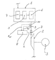
図1は、ソーラーフィールド1、タービン2、そして発電機3を備えたソーラー設備の概略セクションを示している。作動媒体、特に水は、ソーラー設備のソーラーフィールド1内で蒸発させられる。ソーラーフィールド1内で発生させられた生蒸気は、膨張のためにタービン2へと供給される。生蒸気がタービン2内で膨張させられるとき、エネルギーが得られ、これを用いて発電機3を、電気エネルギーを発生させるために駆動させることができる。 FIG. 1 shows a schematic section of a solar installation with a solar field 1, a turbine 2 and a generator 3. The working medium, in particular water, is evaporated in the solar field 1 of the solar installation. Live steam generated in the solar field 1 is supplied to the turbine 2 for expansion. When live steam is expanded in the turbine 2, energy is obtained and can be used to drive the generator 3 to generate electrical energy.
図示する実施形態では、ソーラー設備のソーラーフィールド1は、予熱器4、エバポレーター5、そして過熱器6を備える。作動媒体は、予熱器4内で、蒸発温度まで予熱される。作動媒体の実際の蒸発はエバポレーター5内で生じる。蒸気は過熱器6内で過熱され、そして過熱器6は、膨張のためにタービン2に続いて供給される生蒸気を供給する。
In the illustrated embodiment, the solar field 1 of the solar installation comprises a
膨張のためにタービン2に供給される生蒸気の量は、少なくとも一つのバルブ7によって調整可能である。バルブ7、あるいは各バルブ7は、タービン2の一体型コンポーネント部分であってもよい。
The amount of live steam supplied to the turbine 2 for expansion can be adjusted by means of at least one
本発明の趣旨の範囲で、それを用いてソーラー設備を作動させるためにタービン2に供給される生蒸気の量が調整されるバルブ7あるいは各バルブ7は、タービン2の上流で生じる生蒸気圧力pの実際の値pISTが、タービン2の上流の生蒸気の生蒸気温度Tの実際の値TISTに依存して決定される、対応する参照値pSOLLに追従するように制御される。
Within the scope of the present invention, the
バルブ7あるいは各バルブ7は、好ましくは、このバルブ7のあるいは各バルブ7の直ぐ上流で生じる生蒸気圧力pの実際の値pISTが、既に述べたように、バルブ7あるいは各バルブ7の直ぐ上流の生蒸気の生蒸気温度Tの実際の値TISTに依存して決定される、対応する参照値pSOLLに追従するように制御される。
The
コントローラー8が、本発明に基づく方法を実施するために使用される。タービン2の上流あるいはバルブ7または各バルブ7の上流の生蒸気温度の実際の値TISTは、コントローラー8に供給される。生蒸気温度のこの実際の値TISTは、センサー9によって特定される。生蒸気温度のこの実際の値に依存して、コントローラー8は、タービン2の上流のあるいはバルブ7または各バルブ7の上流の生蒸気の生蒸気圧力に関する参照値pSOLLを決定し、そして生蒸気圧力に関するこの参照値pSOLLに依存して、コントローラー8は、生蒸気圧力の実際の値pISTが生蒸気圧力に関する参照値pSOLLに追従するように、バルブ7または各バルブ7に関する制御変数Xを決定する。
A controller 8 is used to carry out the method according to the invention. The actual value T IST of the raw steam temperature upstream of the turbine 2 or upstream of the
コントローラー8における、生蒸気温度の実際の値TISTに依存する生蒸気圧力に関する参照値pSOLLの決定は、好ましくは、特性ライン7によって実施される。図2は代表的な特性ライン11を示しており、これは、生蒸気温度の実際の値TISTに依存する生蒸気圧力に関する参照値pSOLLを決定するために使用される。
The determination of the reference value p SOLL for the live steam pressure in the controller 8 which depends on the actual value T IST of the live steam temperature is preferably carried out by the
図2の特性ラインにおいては、約30barの生蒸気圧力pSOLLに関する参照値が、約310℃の実際の生蒸気温度TISTにおいて特定される。約280℃の生蒸気の温度TISTにおいて、約19.5barの生蒸気圧力に関する参照値pSOLLが生成される。 In the characteristic line of FIG. 2, a reference value for the live steam pressure p SOLL of about 30 bar is specified at an actual live steam temperature T IST of about 310 ° C. At a live steam temperature T IST of about 280 ° C., a reference value p SOLL for a live steam pressure of about 19.5 bar is generated.
既に述べたように、コントローラー8は、生蒸気圧力の実際の値PISTが生蒸気圧力の参照値pSOLLに追従するように、生蒸気圧力に関する参照値pSOLLに依存して、バルブ7あるいは各バルブ7に関する制御変数Xを決定する。このために、制御変数Xは、好ましくは、生蒸気圧力の参照値pSOLLと生蒸気圧力の実際の値PISTとの間の制御偏差に依存して生成される。図1によれば、生蒸気圧力の実際の値PISTはセンサー10によって決定され、そしてコントローラー8に供給される。
As already mentioned, the controller 8 depends on the reference value p SOLL for the live steam pressure, depending on the reference value p SOLL for the live steam pressure, so that the actual value P IST of the live steam pressure follows the reference value p SOLL for the live steam pressure. A control variable X for each
本発明によれば、部分負荷だけでなく全負荷においても最適効率でソーラー設備を作動させることが可能である。したがって、特に、そこでの日照不足のためにソーラーフィールド1内で生蒸気がほとんど生じない場合に、タービン2を、発電機3によって最大の電気エネルギーを生み出すために最適効率で作動させることができる。本発明は、生蒸気の利用可能な量、有効なエンタルピー低下、そしてソーラー設備の個々のコンポーネント群のローディングの最適な組み合わせを伴ったソーラー設備の作動を可能とする。 According to the present invention, it is possible to operate a solar facility with optimum efficiency not only at a partial load but also at a full load. Thus, the turbine 2 can be operated with optimal efficiency to produce maximum electrical energy by the generator 3, particularly when there is little live steam in the solar field 1 due to lack of sunshine there. The present invention allows for the operation of solar installations with an optimal combination of available amount of live steam, effective enthalpy reduction, and loading of individual components of the solar installation.
1 ソーラーフィールド
2 タービン
3 発電機
4 予熱器
5 エバポレーター
6 過熱器
7 バルブ
8 コントローラー
9 センサー
10 センサー
11 特性ライン
1 Solar Field 2 Turbine 3
Claims (6)
Applications Claiming Priority (2)
| Application Number | Priority Date | Filing Date | Title |
|---|---|---|---|
| DE102012209139.4 | 2012-05-31 | ||
| DE102012209139A DE102012209139A1 (en) | 2012-05-31 | 2012-05-31 | Method for operating a solar system |
Publications (2)
| Publication Number | Publication Date |
|---|---|
| JP2013249840A JP2013249840A (en) | 2013-12-12 |
| JP6242592B2 true JP6242592B2 (en) | 2017-12-06 |
Family
ID=48190416
Family Applications (1)
| Application Number | Title | Priority Date | Filing Date |
|---|---|---|---|
| JP2013113790A Expired - Fee Related JP6242592B2 (en) | 2012-05-31 | 2013-05-30 | Method for operating a solar installation |
Country Status (5)
| Country | Link |
|---|---|
| US (1) | US9745868B2 (en) |
| EP (1) | EP2669480B1 (en) |
| JP (1) | JP6242592B2 (en) |
| CN (1) | CN103452610B (en) |
| DE (1) | DE102012209139A1 (en) |
Families Citing this family (2)
| Publication number | Priority date | Publication date | Assignee | Title |
|---|---|---|---|---|
| CN103925177B (en) * | 2014-03-25 | 2016-08-17 | 戚荣生 | Solar steam electricity generation system |
| JP2023157795A (en) * | 2022-04-15 | 2023-10-26 | 学校法人国士舘 | Fluid expander and fluid expansion unit |
Family Cites Families (12)
| Publication number | Priority date | Publication date | Assignee | Title |
|---|---|---|---|---|
| JPS6048604B2 (en) * | 1976-11-09 | 1985-10-28 | 工業技術院長 | solar power generation system |
| US4484446A (en) * | 1983-02-28 | 1984-11-27 | W. K. Technology, Inc. | Variable pressure power cycle and control system |
| US4888953A (en) * | 1987-11-13 | 1989-12-26 | Babcock-Hitachi Kabushiki Kaisha | Apparatus for controlling boiler/turbine plant |
| DE4340340C1 (en) * | 1993-11-26 | 1995-04-06 | Abb Patent Gmbh | Method and device for determining the fresh steam mass flow in the fresh steam line of a steam-operated power station |
| KR20000053135A (en) | 1996-11-08 | 2000-08-25 | 칼 하인쯔 호르닝어 | Turbine control device and method for regulating the load alternation process in a turbine |
| JP4707927B2 (en) * | 2000-05-31 | 2011-06-22 | シーメンス アクチエンゲゼルシヤフト | Operation method and apparatus for multi-stage steam turbine during no-load or light-load operation |
| CN1318737A (en) | 2001-05-29 | 2001-10-24 | 中国科学院长春光学精密机械与物理研究所 | Preparation of silicon-based organic sound pressure sensor chip for micro optical machine |
| US6981377B2 (en) * | 2002-02-25 | 2006-01-03 | Outfitter Energy Inc | System and method for generation of electricity and power from waste heat and solar sources |
| DE10221594B4 (en) * | 2002-05-15 | 2006-02-16 | AKTIENGESELLSCHAFT KüHNLE, KOPP & KAUSCH | Device and method for efficiency-optimized control of a turbine |
| DE102007013430B9 (en) | 2007-03-13 | 2013-12-24 | Deutsches Zentrum für Luft- und Raumfahrt e.V. | Solar thermal power plant and method for operating a solar thermal power plant |
| WO2011080021A2 (en) * | 2009-12-22 | 2011-07-07 | Siemens Aktiengesellschaft | Solar thermal power plant and method for operating a solar thermal power plant |
| DE102009060089A1 (en) * | 2009-12-22 | 2011-06-30 | Siemens Aktiengesellschaft, 80333 | Solar thermal power plant and method for operating a solar thermal power plant |
-
2012
- 2012-05-31 DE DE102012209139A patent/DE102012209139A1/en not_active Withdrawn
-
2013
- 2013-05-03 EP EP13166469.0A patent/EP2669480B1/en not_active Not-in-force
- 2013-05-30 JP JP2013113790A patent/JP6242592B2/en not_active Expired - Fee Related
- 2013-05-30 US US13/906,033 patent/US9745868B2/en not_active Expired - Fee Related
- 2013-05-31 CN CN201310212000.3A patent/CN103452610B/en not_active Expired - Fee Related
Also Published As
| Publication number | Publication date |
|---|---|
| EP2669480B1 (en) | 2018-10-17 |
| US9745868B2 (en) | 2017-08-29 |
| CN103452610B (en) | 2017-03-01 |
| JP2013249840A (en) | 2013-12-12 |
| DE102012209139A1 (en) | 2013-12-05 |
| CN103452610A (en) | 2013-12-18 |
| US20140013748A1 (en) | 2014-01-16 |
| EP2669480A1 (en) | 2013-12-04 |
Similar Documents
| Publication | Publication Date | Title |
|---|---|---|
| US20100229523A1 (en) | Continuous combined cycle operation power plant and method | |
| US6766646B1 (en) | Rapid power producing system and method for steam turbine | |
| CN105700494B (en) | Model-based combined cycle power plant load control | |
| CA2868093C (en) | Steam temperature control using model-based temperature balancing | |
| RU2011142779A (en) | METHOD AND DEVICE FOR REGULATING STEAM TEMPERATURE FOR STEAM POWER PLANT | |
| GB2482947A (en) | Steam temperature control using disturbance variable rate of change in dynamic matrix control | |
| EP2770172B1 (en) | Method for providing a frequency response for a combined cycle power plant | |
| JP4913087B2 (en) | Control device for combined power plant | |
| JP6242592B2 (en) | Method for operating a solar installation | |
| WO2016157116A1 (en) | Combined control method of an organic rankine cycle | |
| KR101887971B1 (en) | Low load turndown for combined cycle power plants | |
| EP2867735B1 (en) | A method for optimization of control and fault analysis in a thermal power plant | |
| JP5804748B2 (en) | Steam supply system and steam supply method | |
| KR101343007B1 (en) | Combined heat and power plant system | |
| KR102704840B1 (en) | Control device of power plant, power plant and control method of power plant | |
| JP2019536934A (en) | Operating method of combined cycle power plant | |
| KR101656579B1 (en) | Supercritical pressure power plant and variable pressure operation control method thereof | |
| EP2765288A1 (en) | Device and method for calculating the reference load for gas turbines of a combined cycle plant of the"2+1" type and plant comprising said device | |
| KR101499636B1 (en) | Organic Rankine Cycle system with attaching solar expander modules | |
| JPH04110507A (en) | Steam temperature controller of superheater and reheater in cogeneration power plant | |
| US9140143B2 (en) | Method of operating a steam power plant at low load | |
| JP2011117358A (en) | Apparatus and method for controlling heat power plant | |
| EP3209867A1 (en) | System and method for increasing the responsiveness of a duct fired, combined cycle, power generation plant | |
| Li | Application of self adaptation fuzzy-PID control for main steam temperature control system in power station | |
| HK1226460A1 (en) | Model-based combined cycle power plant load control |
Legal Events
| Date | Code | Title | Description |
|---|---|---|---|
| A621 | Written request for application examination |
Free format text: JAPANESE INTERMEDIATE CODE: A621 Effective date: 20160523 |
|
| A977 | Report on retrieval |
Free format text: JAPANESE INTERMEDIATE CODE: A971007 Effective date: 20170313 |
|
| A131 | Notification of reasons for refusal |
Free format text: JAPANESE INTERMEDIATE CODE: A131 Effective date: 20170327 |
|
| A601 | Written request for extension of time |
Free format text: JAPANESE INTERMEDIATE CODE: A601 Effective date: 20170627 |
|
| A521 | Request for written amendment filed |
Free format text: JAPANESE INTERMEDIATE CODE: A523 Effective date: 20170927 |
|
| TRDD | Decision of grant or rejection written | ||
| A01 | Written decision to grant a patent or to grant a registration (utility model) |
Free format text: JAPANESE INTERMEDIATE CODE: A01 Effective date: 20171016 |
|
| A61 | First payment of annual fees (during grant procedure) |
Free format text: JAPANESE INTERMEDIATE CODE: A61 Effective date: 20171108 |
|
| R150 | Certificate of patent or registration of utility model |
Ref document number: 6242592 Country of ref document: JP Free format text: JAPANESE INTERMEDIATE CODE: R150 |
|
| S533 | Written request for registration of change of name |
Free format text: JAPANESE INTERMEDIATE CODE: R313533 |
|
| R350 | Written notification of registration of transfer |
Free format text: JAPANESE INTERMEDIATE CODE: R350 |
|
| R250 | Receipt of annual fees |
Free format text: JAPANESE INTERMEDIATE CODE: R250 |
|
| LAPS | Cancellation because of no payment of annual fees |