JP6281803B2 - 排水装置 - Google Patents
排水装置 Download PDFInfo
- Publication number
- JP6281803B2 JP6281803B2 JP2013024319A JP2013024319A JP6281803B2 JP 6281803 B2 JP6281803 B2 JP 6281803B2 JP 2013024319 A JP2013024319 A JP 2013024319A JP 2013024319 A JP2013024319 A JP 2013024319A JP 6281803 B2 JP6281803 B2 JP 6281803B2
- Authority
- JP
- Japan
- Prior art keywords
- drainage
- container
- water
- peripheral side
- side plate
- Prior art date
- Legal status (The legal status is an assumption and is not a legal conclusion. Google has not performed a legal analysis and makes no representation as to the accuracy of the status listed.)
- Expired - Fee Related
Links
- XLYOFNOQVPJJNP-UHFFFAOYSA-N water Substances O XLYOFNOQVPJJNP-UHFFFAOYSA-N 0.000 claims description 79
- 230000002093 peripheral effect Effects 0.000 claims description 54
- 239000007787 solid Substances 0.000 description 19
- 238000010276 construction Methods 0.000 description 8
- 125000006850 spacer group Chemical group 0.000 description 8
- 238000001035 drying Methods 0.000 description 5
- 230000000694 effects Effects 0.000 description 5
- 238000000034 method Methods 0.000 description 4
- 230000008878 coupling Effects 0.000 description 3
- 238000010168 coupling process Methods 0.000 description 3
- 238000005859 coupling reaction Methods 0.000 description 3
- 238000010981 drying operation Methods 0.000 description 3
- 239000012530 fluid Substances 0.000 description 3
- 238000011144 upstream manufacturing Methods 0.000 description 3
- 239000002351 wastewater Substances 0.000 description 3
- 238000010521 absorption reaction Methods 0.000 description 2
- 230000009471 action Effects 0.000 description 2
- 230000004888 barrier function Effects 0.000 description 2
- 239000003638 chemical reducing agent Substances 0.000 description 2
- 238000007599 discharging Methods 0.000 description 2
- 239000000463 material Substances 0.000 description 2
- 238000005192 partition Methods 0.000 description 2
- 238000005086 pumping Methods 0.000 description 2
- 230000000630 rising effect Effects 0.000 description 2
- 239000004576 sand Substances 0.000 description 2
- 238000004065 wastewater treatment Methods 0.000 description 2
- 238000009825 accumulation Methods 0.000 description 1
- 230000005540 biological transmission Effects 0.000 description 1
- 230000008859 change Effects 0.000 description 1
- 150000001875 compounds Chemical class 0.000 description 1
- 238000000151 deposition Methods 0.000 description 1
- 238000009792 diffusion process Methods 0.000 description 1
- 239000003657 drainage water Substances 0.000 description 1
- 238000009434 installation Methods 0.000 description 1
- 238000011835 investigation Methods 0.000 description 1
- 230000014759 maintenance of location Effects 0.000 description 1
- 230000007246 mechanism Effects 0.000 description 1
- 239000003595 mist Substances 0.000 description 1
- 230000008569 process Effects 0.000 description 1
- 230000000717 retained effect Effects 0.000 description 1
- 238000004062 sedimentation Methods 0.000 description 1
- 230000007480 spreading Effects 0.000 description 1
- 238000003892 spreading Methods 0.000 description 1
- 238000003756 stirring Methods 0.000 description 1
- 238000003860 storage Methods 0.000 description 1
- 239000000126 substance Substances 0.000 description 1
- 239000002699 waste material Substances 0.000 description 1
- 238000003466 welding Methods 0.000 description 1
Images


Landscapes
- Jet Pumps And Other Pumps (AREA)
Description
前記容器状装置本体の周側板の下端に、排水動作時に、排水対象部位の底面との間に微小隙間をあけるための複数の隙間形成用の微小突起を突出させたものである。
なお、前記のように、前記排水案内管は、排水口から斜め上向きに延びる剛性かつ直線状の管体で構成したものであるから、吸引した滞留水をその先端吐出口である排水端まで案内して吐出排水することにより、例えば、排水対象部位が何らかの仕切りで囲まれてい る場合であっても、その仕切りを越えてその外側の排出先まで案内し吐出排水させることができる。
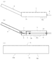
この実施例1の排水装置は、図1(a)〜(c)及び図2(a),(b)に示すように、平面視四辺形(正方形)の下部開口の容器状装置本体1と、圧縮空気を該容器状装置本体1の内部空間からその先端側に位置する排水口2に噴出させるノズル部3と、該排水口2から空気噴流及び排水対象水を外部に案内排出する排水案内管4とで構成したものである。
なおまた、この実施例では、この容器状装置本体1は、下部開口の平面視正方形の部材に構成したが、これに限定されず、平面視長方形、三角形又は五角形以上の多角形、円形、楕円形又は不定形に構成することも可能である。
なお、この実施例1の排水装置で砂利を敷設した領域の排水処理を行ったが、これも良好に実施できた。
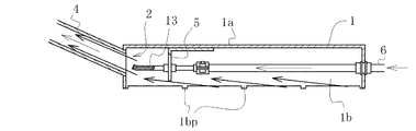
実施例2の排水装置は、図4に示すように、そのノズル部13が以上の実施例1のノズル部3と異なるのみで、他は全て同一である。図中、実施例1と同一の構成をもった要素にはそれと同一の符号を付してある。このノズル部13は、同図に示すように、その先端の噴口が前記排水口2の直前に位置し、実施例1のそれのように排水口2の内部まで進入していないものである。このノズル部13によれば、排水動作時に、その先端の噴口から噴出される空気噴流によって吸引される水流は、若干広がりつつ排水口2側に噴射流になって移動するが、その噴射流の全部が該排水口2中に入って行くことができる位置関係となっている。
実施例3の排水装置は、図5(a)に示すように、その容器状装置本体11を平面視円形に構成したものであり、それ故、天板部11aも平面視円形であり、周側板11bもまた底面視円弧状である。周側板11bの高さ寸法は実施例1の周側板1bと同様である。その他の構成要素は、図5(a)、(b)に示すように、全て実施例1のそれと同一であり、同一の符号を用いている。
実施例4の排水装置は、図6(a)〜(c)に示すように、ノズル部3に接続するホース部材16の通過経路が実施例1のそれと異なる他は、実施例1の排水装置と全く同様の構成である。図6中では、実施例1の構成要素と同様の構成の構成要素には同一の符号を付してある。
実施例5は、図7(a)、(b)及び図8(a)、(b)に示すように、容器状装置本体21の周側板21bの高さ方向の寸法及び排水案内管24の周側板21bへの取付角度及びノズル部23の先端の位置のそれぞれが実施例1のそれらと異なるほかは、実施例1のそれらと全く同様の構成である。それ故、実施例1のそれぞれと同一構成要素には同一の符号を付してある。
実施例6は、図9(a)〜(c)に示すように、容器状装置本体31へのノズル部33及びホース部材36の取り付け方並びに排水案内管34の容器状装置本体31への取り付け方、更に容器状装置本体31の周側板31bの高さ寸法が小さいことのそれぞれが実施例1のそれらと異なる他は、実施例1のそれらと全く同様の構成である。
1a 天板部
1b 周側板
1bp 微小突起
2 排水口
3 ノズル部
4 排水案内管
5 L型の固定片
6 ホース部材
7 ベタ基礎
8 コンプレッサ
9 側溝
11 容器状装置本体
11a 天板部
11b 周側板
13 ノズル部
16 ホース部材
21 容器状装置本体
21a 天板部
21b 周側板
23 ノズル部
24 排水案内管
31 容器状装置本体
31a 天板部
31b 周側板
31bp 微小突起
32 排水口
33 ノズル部
34 排水案内管
35a スペーサ板
35b 取付部材
35b1 部分円弧状凹部
35b2 取付板
35c スペーサ板
35d 取付部材
35d1 部分円弧状凹部
35d2 取付板
36 ホース部材
ws 水面
Claims (2)
- 上面を天板部で、周囲を下方に垂下する周側板で、それぞれ閉じた下部開口の容器状装置本体と、圧縮空気を導入し、その圧縮空気を前記容器状装置本体の内部空間から排水口に噴出させるノズル部と、前記容器状装置本体の先端側の天板部又は周側板に開口した排水口であって、排水動作時に前記ノズル部から噴出する空気噴流により前記周側板の下端と排水対象部位の底面との間から吸引される排水対象水を該空気噴流と共に排水する排水口と、該排水口から該排水対象水及び該空気噴流を外部に案内排水する、外端が排水端である排水案内管であって、該排水口から斜め上向きに延びる剛性かつ直線状の管体で構成した排水案内管と、で構成した排水装置。
- 前記容器状装置本体の周側板の下端に、排水動作時に、排水対象部位の底面との間に微小隙間をあけるための複数の隙間形成用の微小突起を突出させた請求項1の排水装置。
Priority Applications (1)
| Application Number | Priority Date | Filing Date | Title |
|---|---|---|---|
| JP2013024319A JP6281803B2 (ja) | 2013-02-12 | 2013-02-12 | 排水装置 |
Applications Claiming Priority (1)
| Application Number | Priority Date | Filing Date | Title |
|---|---|---|---|
| JP2013024319A JP6281803B2 (ja) | 2013-02-12 | 2013-02-12 | 排水装置 |
Publications (2)
| Publication Number | Publication Date |
|---|---|
| JP2014152728A JP2014152728A (ja) | 2014-08-25 |
| JP6281803B2 true JP6281803B2 (ja) | 2018-02-21 |
Family
ID=51574821
Family Applications (1)
| Application Number | Title | Priority Date | Filing Date |
|---|---|---|---|
| JP2013024319A Expired - Fee Related JP6281803B2 (ja) | 2013-02-12 | 2013-02-12 | 排水装置 |
Country Status (1)
| Country | Link |
|---|---|
| JP (1) | JP6281803B2 (ja) |
Families Citing this family (2)
| Publication number | Priority date | Publication date | Assignee | Title |
|---|---|---|---|---|
| JP7378710B2 (ja) * | 2018-11-12 | 2023-11-14 | 株式会社サーフェステクノロジー | 排水吸引回収装置 |
| JP6739887B1 (ja) * | 2019-12-20 | 2020-08-12 | 正通 亀井 | 水害時2次排水方法 |
Family Cites Families (7)
| Publication number | Priority date | Publication date | Assignee | Title |
|---|---|---|---|---|
| JPS4833045Y1 (ja) * | 1970-08-26 | 1973-10-08 | ||
| JPS5430099U (ja) * | 1977-08-02 | 1979-02-27 | ||
| JPS54126202U (ja) * | 1978-02-23 | 1979-09-03 | ||
| JPS57144300U (ja) * | 1981-03-04 | 1982-09-10 | ||
| JPH0329597Y2 (ja) * | 1986-10-01 | 1991-06-24 | ||
| JPH08303399A (ja) * | 1995-05-01 | 1996-11-19 | Ogawa Jidosha:Kk | バキュ−ムポンプユニットによる汚泥水の超高揚程吸い上げ方法及びその装置 |
| JP2012233447A (ja) * | 2011-05-06 | 2012-11-29 | Ihi Corp | 水中ポンプ装置 |
-
2013
- 2013-02-12 JP JP2013024319A patent/JP6281803B2/ja not_active Expired - Fee Related
Also Published As
| Publication number | Publication date |
|---|---|
| JP2014152728A (ja) | 2014-08-25 |
Similar Documents
| Publication | Publication Date | Title |
|---|---|---|
| JP5179159B2 (ja) | 揚砂装置 | |
| US20140202941A1 (en) | Whirlpool skimmer | |
| JP2010036151A (ja) | 揚砂装置 | |
| US8728307B2 (en) | Whirlpool skimmer | |
| KR101463223B1 (ko) | 지하수 관정과 지열공 토사슬러리 배출 장치 및 방법 | |
| JP6281803B2 (ja) | 排水装置 | |
| JP2013202570A (ja) | 集砂ノズル及び集砂ノズル装置 | |
| JP2011144616A (ja) | ポンプによる揚泥方法及び揚泥設備 | |
| CN106703175A (zh) | 卧式一体化自清干式泵站 | |
| KR102145976B1 (ko) | 이동 통신용 강관주 및 그 시공 방법 | |
| JP2016156243A (ja) | 側溝排水装置 | |
| JP2000126514A (ja) | 汚水処理槽の排泥装置 | |
| JP5872960B2 (ja) | 釜場の構造 | |
| US4797028A (en) | Beaver control siphon apparatus | |
| JP2005188490A (ja) | サンドポンプ | |
| JP4521626B2 (ja) | 井戸の揚水ポンプ装置 | |
| JP5808008B2 (ja) | 吸引力発生装置および真空圧密地盤改良工法 | |
| CN109458146A (zh) | 用于灌注桩孔底大粒径沉渣的清孔装置 | |
| JP2014076449A (ja) | 揚砂方法 | |
| CN206337635U (zh) | 卧式一体化自清干式泵站 | |
| CN206338917U (zh) | 一种防沙排沙装置 | |
| KR100713212B1 (ko) | 하수박스 내부 퇴적토 방류시설 | |
| KR102928650B1 (ko) | 제트펌프 | |
| JP2005111383A (ja) | 集砂槽 | |
| JP4588344B2 (ja) | 水中サンドポンプ |
Legal Events
| Date | Code | Title | Description |
|---|---|---|---|
| RD04 | Notification of resignation of power of attorney |
Free format text: JAPANESE INTERMEDIATE CODE: A7424 Effective date: 20140520 |
|
| A621 | Written request for application examination |
Free format text: JAPANESE INTERMEDIATE CODE: A621 Effective date: 20160114 |
|
| A977 | Report on retrieval |
Free format text: JAPANESE INTERMEDIATE CODE: A971007 Effective date: 20160920 |
|
| A131 | Notification of reasons for refusal |
Free format text: JAPANESE INTERMEDIATE CODE: A131 Effective date: 20161011 |
|
| A131 | Notification of reasons for refusal |
Free format text: JAPANESE INTERMEDIATE CODE: A131 Effective date: 20170411 |
|
| A521 | Request for written amendment filed |
Free format text: JAPANESE INTERMEDIATE CODE: A523 Effective date: 20170526 |
|
| A521 | Request for written amendment filed |
Free format text: JAPANESE INTERMEDIATE CODE: A523 Effective date: 20170703 |
|
| TRDD | Decision of grant or rejection written | ||
| A01 | Written decision to grant a patent or to grant a registration (utility model) |
Free format text: JAPANESE INTERMEDIATE CODE: A01 Effective date: 20180109 |
|
| A61 | First payment of annual fees (during grant procedure) |
Free format text: JAPANESE INTERMEDIATE CODE: A61 Effective date: 20180112 |
|
| R150 | Certificate of patent or registration of utility model |
Ref document number: 6281803 Country of ref document: JP Free format text: JAPANESE INTERMEDIATE CODE: R150 |
|
| R250 | Receipt of annual fees |
Free format text: JAPANESE INTERMEDIATE CODE: R250 |
|
| LAPS | Cancellation because of no payment of annual fees |