JP6380802B2 - 眼軸長を測定するためのマイケルソン型干渉計及び測定方法 - Google Patents
眼軸長を測定するためのマイケルソン型干渉計及び測定方法 Download PDFInfo
- Publication number
- JP6380802B2 JP6380802B2 JP2014552743A JP2014552743A JP6380802B2 JP 6380802 B2 JP6380802 B2 JP 6380802B2 JP 2014552743 A JP2014552743 A JP 2014552743A JP 2014552743 A JP2014552743 A JP 2014552743A JP 6380802 B2 JP6380802 B2 JP 6380802B2
- Authority
- JP
- Japan
- Prior art keywords
- reflecting surface
- light source
- reflecting
- distance
- optical path
- Prior art date
- Legal status (The legal status is an assumption and is not a legal conclusion. Google has not performed a legal analysis and makes no representation as to the accuracy of the status listed.)
- Active
Links
Images




Classifications
-
- A—HUMAN NECESSITIES
- A61—MEDICAL OR VETERINARY SCIENCE; HYGIENE
- A61B—DIAGNOSIS; SURGERY; IDENTIFICATION
- A61B3/00—Apparatus for testing the eyes; Instruments for examining the eyes
- A61B3/10—Objective types, i.e. instruments for examining the eyes independent of the patients' perceptions or reactions
- A61B3/1005—Objective types, i.e. instruments for examining the eyes independent of the patients' perceptions or reactions for measuring distances inside the eye, e.g. thickness of the cornea
-
- A—HUMAN NECESSITIES
- A61—MEDICAL OR VETERINARY SCIENCE; HYGIENE
- A61B—DIAGNOSIS; SURGERY; IDENTIFICATION
- A61B3/00—Apparatus for testing the eyes; Instruments for examining the eyes
- A61B3/0016—Operational features thereof
- A61B3/0025—Operational features thereof characterised by electronic signal processing, e.g. eye models
-
- A—HUMAN NECESSITIES
- A61—MEDICAL OR VETERINARY SCIENCE; HYGIENE
- A61B—DIAGNOSIS; SURGERY; IDENTIFICATION
- A61B3/00—Apparatus for testing the eyes; Instruments for examining the eyes
- A61B3/0075—Apparatus for testing the eyes; Instruments for examining the eyes provided with adjusting devices, e.g. operated by control lever
-
- A—HUMAN NECESSITIES
- A61—MEDICAL OR VETERINARY SCIENCE; HYGIENE
- A61B—DIAGNOSIS; SURGERY; IDENTIFICATION
- A61B3/00—Apparatus for testing the eyes; Instruments for examining the eyes
- A61B3/10—Objective types, i.e. instruments for examining the eyes independent of the patients' perceptions or reactions
- A61B3/102—Objective types, i.e. instruments for examining the eyes independent of the patients' perceptions or reactions for optical coherence tomography [OCT]
-
- A—HUMAN NECESSITIES
- A61—MEDICAL OR VETERINARY SCIENCE; HYGIENE
- A61B—DIAGNOSIS; SURGERY; IDENTIFICATION
- A61B3/00—Apparatus for testing the eyes; Instruments for examining the eyes
- A61B3/10—Objective types, i.e. instruments for examining the eyes independent of the patients' perceptions or reactions
- A61B3/14—Arrangements specially adapted for eye photography
-
- G—PHYSICS
- G01—MEASURING; TESTING
- G01B—MEASURING LENGTH, THICKNESS OR SIMILAR LINEAR DIMENSIONS; MEASURING ANGLES; MEASURING AREAS; MEASURING IRREGULARITIES OF SURFACES OR CONTOURS
- G01B9/00—Measuring instruments characterised by the use of optical techniques
- G01B9/02—Interferometers
- G01B9/02015—Interferometers characterised by the beam path configuration
- G01B9/02025—Interference between three or more discrete surfaces
-
- G—PHYSICS
- G01—MEASURING; TESTING
- G01B—MEASURING LENGTH, THICKNESS OR SIMILAR LINEAR DIMENSIONS; MEASURING ANGLES; MEASURING AREAS; MEASURING IRREGULARITIES OF SURFACES OR CONTOURS
- G01B9/00—Measuring instruments characterised by the use of optical techniques
- G01B9/02—Interferometers
- G01B9/02015—Interferometers characterised by the beam path configuration
- G01B9/02027—Two or more interferometric channels or interferometers
- G01B9/02028—Two or more reference or object arms in one interferometer
-
- G—PHYSICS
- G01—MEASURING; TESTING
- G01B—MEASURING LENGTH, THICKNESS OR SIMILAR LINEAR DIMENSIONS; MEASURING ANGLES; MEASURING AREAS; MEASURING IRREGULARITIES OF SURFACES OR CONTOURS
- G01B9/00—Measuring instruments characterised by the use of optical techniques
- G01B9/02—Interferometers
- G01B9/02055—Reduction or prevention of errors; Testing; Calibration
- G01B9/02075—Reduction or prevention of errors; Testing; Calibration of particular errors
- G01B9/02076—Caused by motion
- G01B9/02077—Caused by motion of the object
-
- G—PHYSICS
- G01—MEASURING; TESTING
- G01B—MEASURING LENGTH, THICKNESS OR SIMILAR LINEAR DIMENSIONS; MEASURING ANGLES; MEASURING AREAS; MEASURING IRREGULARITIES OF SURFACES OR CONTOURS
- G01B9/00—Measuring instruments characterised by the use of optical techniques
- G01B9/02—Interferometers
- G01B9/0209—Low-coherence interferometers
Landscapes
- Health & Medical Sciences (AREA)
- Life Sciences & Earth Sciences (AREA)
- Physics & Mathematics (AREA)
- Engineering & Computer Science (AREA)
- General Physics & Mathematics (AREA)
- Heart & Thoracic Surgery (AREA)
- Molecular Biology (AREA)
- Ophthalmology & Optometry (AREA)
- Veterinary Medicine (AREA)
- Biomedical Technology (AREA)
- Public Health (AREA)
- Medical Informatics (AREA)
- Biophysics (AREA)
- Surgery (AREA)
- Animal Behavior & Ethology (AREA)
- General Health & Medical Sciences (AREA)
- Nuclear Medicine, Radiotherapy & Molecular Imaging (AREA)
- Radiology & Medical Imaging (AREA)
- Signal Processing (AREA)
- Eye Examination Apparatus (AREA)
Description
1)Rf、Rs、Δkの3つのサイズを計測する角膜測定器。この測定は、パラメータRfおよびRs(平面体の子午線半径および曲面体の子午線半径)、ならびに、前記2つの半径間の差異を表すパラメータΔkの検出による、角膜の形状の評価に適する。
2)前房中央奥行き(ACD):このパラメータによって、角膜の後面と水晶体の前面との間の眼内距離が測定され、一般的に、約2÷4mm程度のものである。
3)軸長(AL):代わって、この第3のパラメータによって、角膜および網膜の外面間の眼軸長が測定され、これの平均距離は約25mmである。
−異なる焦点距離における複数の画像を取得するように、かつ、焦点を合わせた画像を選択するように構成される画像の取得/分析システム(300、400);および、
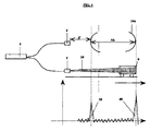
−前記取得された画像に基づいて、取得された画像が合焦点の時に、第1の反射面(8)が検出すべき軸長(AL)の第1の表面(100)と基本的に干渉距離に位置するように、干渉計(1)を移動させることを可能にする移動システム(210)。
−第1の反射面(8)が、目の角膜(100)からコリメータ(4)までの距離(d’)よりも短い、コリメータ(5)からの距離(d’’)で確認されるように、反射装置(7)の最初の位置付けを行うこと;
−2つのコリメータ(4、5)において終止する2つの分岐(4’、5’)によって光ビームを送ること;
−それぞれ、コリメータ(5)から第1の反射面(8)までの光学距離がコリメータ(4)に対する目の角膜(100)の光学距離に等しい、および、コリメータ(5)から第2の反射面(9)までの光学距離が網膜からコリメータ(4)までの光学距離に等しい2つの干渉位置への到達に対応して、2つの干渉ピーク(30、40)の生成が行われるように、測定方向に沿って、1回の移動運動で動作する反射装置を移動させること;および、
−少なくとも、走査段階における装置(7)の移動中、前記相互間の距離(d)を一定に保つように、装置(7)において2つの表面(8、9)が配置されることで、第1の反射面(8)が、移動開始時に第1の干渉ピークを生成した後、前記移動中に、第2の反射面(9)が第2の干渉ピークを生成すること。
Claims (12)
- 眼軸長(AL)を測定するためのマイケルソン型干渉計(1)であって、前記マイケルソン型干渉計(1)は、本体と移動システム(210)を備え、
前記本体は、光源(2)、第1のコリメータ(5)、第2の単一のコリメータ(4)、電動駆動システム(500)、画像の取得/分析システム(300、400)を備え、
前記第1のコリメータ(5)は前記光源(2)から発光された第1の光線を、少なくとも部分的に光を反射する反射装置(7)にコリメートし、前記反射装置(7)は前記第1の光線をコリメートする前記第1のコリメータ(5)に対して離れたり近づいたりすることができ、前記反射装置(7)は縦方向に整列した第1の反射面(8)と第2の反射面(9)を少なくとも備え、前記第1の反射面(8)と第2の反射面(9)はともに少なくとも部分的に光を反射し、互いに所定の相互距離を隔てて配置され、
前記第1の反射面(8)と第2の反射面(9)は、少なくとも測定の間における前記反射装置(7)の移動中、前記反射装置(7)の中で前記所定の相互距離を維持し、
前記第2の単一のコリメータ(4)は前記光源(2)から発光された第2の光線を眼の表面に当て、
前記電動駆動システム(500)は前記反射装置(7)を移動させ、
前記画像の取得/分析システム(300、400)は、前記本体と目の角膜との距離が異なる目の角膜の複数の画像を取得し、前記複数の画像の中から合焦点の画像を選択するように構成され、
前記移動システム(210)は取得された画像に基づいて、目の角膜の画像が合焦点となる位置に前記本体を移動し、
前記電動駆動システム(500)は前記反射装置(7)を、前記第1の反射面(8)が前記光源(2)から、前記光源(2)と角膜との光路長より小さい、ある光路長に位置し、かつ、前記第2の反射面(9)が前記光源(2)から、前記光源(2)と角膜との光路長よりは大きいが前記光源(2)と網膜との光路長よりは小さい、ある光路長に位置する、初期位置に移動するように構成され、
前記第1の反射面(8)と前記第2の反射面(9)との間の距離は12〜19mmで、かつ、前記第1の反射面(8)と前記第2の反射面(9)との間の物質の屈折率は1.5であって、
前記反射装置(7)の一方向への移動が始まり、前記第1の反射面(8)の前記光源(2)からの光路長が目の角膜の前記光源(2)からの光路長と同じになったときに第1の干渉ピークが発生し、次に、前記第1の反射面(8)と前記第2の反射面(9)の間の距離を固定したままで一方向に移動する間に、前記第2の反射面(9)の前記光源(2)からの光路長が前記眼の網膜の前記光源(2)からの光路長と同じになったときに第2の干渉ピークが発生することによって、前記初期位置から開始される一方向への、繰り返しのない、単一の移動による測定を可能にする、干渉計(1)。 - 前記第1の反射面(8)と前記第2の反射面(9)は、互いに平行に配置される、請求項1に記載の干渉計(1)。
- 前記第1の反射面(8)と前記第2の反射面(9)は、互いに同軸に配置される、請求項1または2に記載の干渉計(1)。
- 前記反射装置(7)の前記第1の反射面(8)と前記第2の反射面(9)を相互にスライドして測定前に相互の距離を調整する調整手段と、前記相互の距離を固定する固定手段を備える、請求項1〜3のうちいずれか一項に記載の干渉計(1)。
- 前記第1の反射面(8)と前記第2の反射面(9)が相互間の距離を一定に保つように固定されている、請求項1〜3のうちいずれか一項に記載の干渉計(1)。
- 前記反射装置(7)は円筒形状を有する、請求項1〜5のうちいずれか一項に記載の干渉計(1)。
- 前記第1の反射面(8)と前記第2の反射面(9)との間の距離は12.5mmである請求項1に記載の干渉計(1)。
- 前記電動システム(500)は、前記反射装置(7)の一方の端部と他方の端部の間の移動を命令する電子プロセッサ(PC)に接続される、請求項1に記載の干渉計。
- 前記第1および第2の反射面(8、9)は、反射率が低く、当該反射面に照射される第1の光線の1%〜4%を反射する、請求項1〜8のうちいずれか一項に記載の干渉計(1)。
- 前記本体が配置されたフレーム(200)をさらに含み、前記フレーム(200)は、前記移動システム(210)を制御することにより、前記本体と目の角膜との異なる距離での画像取得を可能にするように往復可能である、請求項1に記載の干渉計(1)。
- マイケルソン型干渉計(1)により眼軸長(AL)を測定する方法であって、前記マイケルソン型干渉計(1)は、本体と移動システム(210)を備え、
前記本体は、光源(2)、第1のコリメータ(5)、第2の単一のコリメータ(4)、電動駆動システム(500)、画像の取得/分析システム(300、400)を備え、
前記第1のコリメータ(5)は前記光源(2)から発光された第1の光線を、少なくとも部分的に光を反射する反射装置(7)にコリメートし、前記反射装置(7)は前記第1の光線を発光する前記光源(2)に対して離れたり近づいたりすることができ、前記反射装置(7)は縦方向に整列した第1の反射面(8)と第2の反射面(9)を少なくとも備え、前記第1の反射面(8)と第2の反射面(9)はともに少なくとも部分的に光を反射し、互いに所定の相互距離を隔てて配置され、
前記第1の反射面(8)と第2の反射面(9)は、少なくとも測定の間における前記反射装置(7)の移動中、前記反射装置(7)の中で前記所定の相互距離を維持し、
前記第2の単一のコリメータ(4)は前記光源(2)から発光された第2の光線を眼の表面に当て、
前記電動駆動システム(500)は前記反射装置(7)を移動させ、
前記画像の取得/分析システム(300、400)は、前記本体と目の角膜との距離が異なる複数の画像を取得し、前記複数の画像の中から角膜の合焦点の画像を選択するように構成され、
前記移動システム(210)は取得された画像に基づいて、前記本体を角膜の画像が合焦点の位置に移動するように構成され、
前記電動駆動システム(500)は前記反射装置(7)を、前記第1の反射面(8)が前記光源(2)から、前記光源(2)と角膜との光路長より小さい、ある光路長に位置し、かつ、前記第2の反射面(9)が前記光源(2)から、前記光源(2)と角膜との光路長よりは大きいが前記光源(2)と網膜との光路長よりは小さい、ある光路長に位置する、初期位置に移動するように構成され、
前記第1の反射面(8)と前記第2の反射面(9)との間の距離は12〜19mmで、かつ、前記第1の反射面(8)と前記第2の反射面(9)との間の物質の屈折率は1.5であって、
前記方法は、
取得される目の角膜の画像が合焦点となる位置に前記本体を移動するステップ、
前記反射装置(7)を前記初期位置に移動するステップ、
前記第1の光線を前記第1のコリメータ(5)に、前記第2の光線を前記第2のコリメータ(4)に送るステップ、および
前記反射装置(7)を測定方向に沿って繰り返しのない、1回のみの移動を行い、第1の、及び第2の干渉位置で、第1の、及び第2の干渉ピークを発生させるステップ、を含み、
前記第1の干渉位置では、前記光源(2)から前記第1の反射面(8)までの光路長は目の角膜と前記光源(2)との間の光路長に等しく、
前記第2の干渉位置では、前記光源(2)から前記第2の反射面(9)までの光路長は眼の網膜と前記光源(2)との間の光路長に等しく、
前記反射装置(7)に配置された前記第1の反射面(8)と前記第2の反射面(9)は測定時、前記反射装置(7)の移動の間、相互の距離を一定に保ち、前記一方向への移動中に、第1の反射面(8)が第1の干渉ピークを発生させ、その後同一方向への移動の間に第2の反射面(9)が第2の干渉ピークを発生させる、方法。 - 前記第1の反射面(8)と第2の反射面(9)の間の距離は、眼軸長の計測結果が変動しても、変更する必要がないことを特徴とする請求項11に記載の方法。
Applications Claiming Priority (3)
| Application Number | Priority Date | Filing Date | Title |
|---|---|---|---|
| IT000009A ITPI20120009A1 (it) | 2012-01-24 | 2012-01-24 | "un metodo per ridurre il tempo della misura a scansione della lunghezza assiale oculare e dispositivo per attuare tale metodo" |
| ITPI2012A000009 | 2012-01-24 | ||
| PCT/IB2013/050621 WO2013111090A1 (en) | 2012-01-24 | 2013-01-24 | Fast measurement of ocular axial length |
Publications (3)
| Publication Number | Publication Date |
|---|---|
| JP2015503989A JP2015503989A (ja) | 2015-02-05 |
| JP2015503989A5 JP2015503989A5 (ja) | 2017-08-03 |
| JP6380802B2 true JP6380802B2 (ja) | 2018-08-29 |
Family
ID=46000150
Family Applications (1)
| Application Number | Title | Priority Date | Filing Date |
|---|---|---|---|
| JP2014552743A Active JP6380802B2 (ja) | 2012-01-24 | 2013-01-24 | 眼軸長を測定するためのマイケルソン型干渉計及び測定方法 |
Country Status (5)
| Country | Link |
|---|---|
| US (1) | US20140347630A1 (ja) |
| EP (1) | EP2814377B1 (ja) |
| JP (1) | JP6380802B2 (ja) |
| IT (1) | ITPI20120009A1 (ja) |
| WO (1) | WO2013111090A1 (ja) |
Families Citing this family (2)
| Publication number | Priority date | Publication date | Assignee | Title |
|---|---|---|---|---|
| JP2016077774A (ja) | 2014-10-22 | 2016-05-16 | 株式会社トプコン | 眼科装置 |
| EP3273839B1 (en) | 2015-03-25 | 2022-06-22 | AMO Development, LLC | Multiple depth optical coherence tomography system and method and laser eye surgery system incorporating the same |
Family Cites Families (17)
| Publication number | Priority date | Publication date | Assignee | Title |
|---|---|---|---|---|
| JP2763584B2 (ja) * | 1989-05-09 | 1998-06-11 | 株式会社トプコン | 生体眼の前後径距離測定装置 |
| US5042938A (en) * | 1989-05-09 | 1991-08-27 | Kabushiki Kaisha Topcon | Apparatus for measuring length of visual line length, depth of anterior chamber, thickness of crystal lens, etc. |
| JPH02295537A (ja) * | 1989-05-09 | 1990-12-06 | Topcon Corp | 生体眼の前後径距離測定装置 |
| US6198540B1 (en) * | 1997-03-26 | 2001-03-06 | Kowa Company, Ltd. | Optical coherence tomography have plural reference beams of differing modulations |
| US6053613A (en) * | 1998-05-15 | 2000-04-25 | Carl Zeiss, Inc. | Optical coherence tomography with new interferometer |
| WO2003086180A2 (de) * | 2002-04-18 | 2003-10-23 | Haag-Streit Ag | Messung optischer eigenschaften |
| US20050140981A1 (en) * | 2002-04-18 | 2005-06-30 | Rudolf Waelti | Measurement of optical properties |
| CA2448346C (en) * | 2003-11-06 | 2012-05-15 | Michael Failes | Fiber optic scanning interferometer using a polarization splitting coupler |
| JP4761774B2 (ja) * | 2005-01-12 | 2011-08-31 | 東京エレクトロン株式会社 | 温度/厚さ測定装置,温度/厚さ測定方法,温度/厚さ測定システム,制御システム,制御方法 |
| US7982881B2 (en) * | 2005-12-06 | 2011-07-19 | Carl Zeiss Meditec Ag | Apparatus and method for interferometric measurement of a sample |
| US8727532B2 (en) * | 2007-07-24 | 2014-05-20 | Sis Ag, Surgical Instrument Systems | Ophthalmological measurement apparatus and measurement method |
| US7800759B2 (en) * | 2007-12-11 | 2010-09-21 | Bausch & Lomb Incorporated | Eye length measurement apparatus |
| PL2230990T3 (pl) * | 2007-12-21 | 2017-08-31 | Bausch & Lomb Incorporated | Urządzenie do justowania przyrządu okulistycznego oraz sposób jego zastosowania |
| DE102008029479A1 (de) * | 2008-06-20 | 2009-12-24 | Carl Zeiss Meditec Ag | Kurzkohärenz-Interferometerie zur Abstandsmessung |
| US8605287B2 (en) * | 2008-07-21 | 2013-12-10 | Optovue, Inc. | Extended range imaging |
| JP5404078B2 (ja) * | 2009-02-03 | 2014-01-29 | 株式会社トプコン | 光画像計測装置 |
| EP2822452A4 (en) * | 2012-03-07 | 2016-03-02 | Optovue Inc | IMPROVED BIOMETRY BY OPTICAL COHERENCE TOMOGRAPHY |
-
2012
- 2012-01-24 IT IT000009A patent/ITPI20120009A1/it unknown
-
2013
- 2013-01-24 JP JP2014552743A patent/JP6380802B2/ja active Active
- 2013-01-24 WO PCT/IB2013/050621 patent/WO2013111090A1/en not_active Ceased
- 2013-01-24 US US14/373,738 patent/US20140347630A1/en not_active Abandoned
- 2013-01-24 EP EP13712330.3A patent/EP2814377B1/en active Active
Also Published As
| Publication number | Publication date |
|---|---|
| EP2814377C0 (en) | 2026-03-04 |
| ITPI20120009A1 (it) | 2013-07-25 |
| JP2015503989A (ja) | 2015-02-05 |
| EP2814377B1 (en) | 2026-03-04 |
| WO2013111090A1 (en) | 2013-08-01 |
| EP2814377A1 (en) | 2014-12-24 |
| US20140347630A1 (en) | 2014-11-27 |
Similar Documents
| Publication | Publication Date | Title |
|---|---|---|
| US9149181B2 (en) | Tomographic imaging apparatus and photographing method | |
| CN104640497B (zh) | 扫描激光检眼镜中的改进或有关扫描激光检眼镜的改进 | |
| JP3756993B2 (ja) | 動的コヒーレント焦点によるコヒーレンス生物測定及び断層撮影の方法 | |
| EP1738680B1 (en) | Ophthalmic apparatus | |
| US8678588B2 (en) | Optical coherence tomographic imaging apparatus | |
| US6806963B1 (en) | Method and device for measuring the optical properties of at least two regions located at a distance from one another in a transparent and/or diffuse object | |
| JP5946654B2 (ja) | 眼科装置 | |
| JP4287290B2 (ja) | 光学的特性の測定 | |
| US9820645B2 (en) | Ophthalmologic apparatus | |
| JP2021527552A5 (ja) | ||
| CN113558563B (zh) | 一种基于oct的眼轴测量方法及装置 | |
| US20050140981A1 (en) | Measurement of optical properties | |
| KR20180059820A (ko) | 코히런스-게이트 파면-센서리스 적응 광학계 다중-광자 현미경 및 관련 시스템 및 방법 | |
| JP4948902B2 (ja) | 眼科装置 | |
| CN104011498B (zh) | 用于扫频光学相干层析成像的设备及方法 | |
| US10918277B2 (en) | Ophthalmic device | |
| JP4746564B2 (ja) | 眼の部分区間長測定のためのショートコヒーレンス干渉計 | |
| CN110123262A (zh) | 眼科测量系统和方法 | |
| JP2015503989A5 (ja) | ||
| JP7187777B2 (ja) | Oct装置、およびoct制御プログラム | |
| JP2015503989A (ja) | 眼軸長の高速測定 | |
| JP2003052632A (ja) | 眼特性測定装置 | |
| US11578965B2 (en) | Cost-effective line-scan optical coherence tomography apparatus | |
| CN115778312A (zh) | 眼科装置 | |
| JP2007010589A (ja) | 物体測定装置 |
Legal Events
| Date | Code | Title | Description |
|---|---|---|---|
| A621 | Written request for application examination |
Free format text: JAPANESE INTERMEDIATE CODE: A621 Effective date: 20160118 |
|
| A521 | Request for written amendment filed |
Free format text: JAPANESE INTERMEDIATE CODE: A523 Effective date: 20160323 |
|
| A131 | Notification of reasons for refusal |
Free format text: JAPANESE INTERMEDIATE CODE: A131 Effective date: 20161101 |
|
| A977 | Report on retrieval |
Free format text: JAPANESE INTERMEDIATE CODE: A971007 Effective date: 20161031 |
|
| A601 | Written request for extension of time |
Free format text: JAPANESE INTERMEDIATE CODE: A601 Effective date: 20170130 |
|
| A524 | Written submission of copy of amendment under article 19 pct |
Free format text: JAPANESE INTERMEDIATE CODE: A524 Effective date: 20170223 |
|
| A521 | Request for written amendment filed |
Free format text: JAPANESE INTERMEDIATE CODE: A523 Effective date: 20170523 |
|
| A131 | Notification of reasons for refusal |
Free format text: JAPANESE INTERMEDIATE CODE: A131 Effective date: 20171024 |
|
| A521 | Request for written amendment filed |
Free format text: JAPANESE INTERMEDIATE CODE: A523 Effective date: 20180124 |
|
| TRDD | Decision of grant or rejection written | ||
| A01 | Written decision to grant a patent or to grant a registration (utility model) |
Free format text: JAPANESE INTERMEDIATE CODE: A01 Effective date: 20180619 |
|
| A61 | First payment of annual fees (during grant procedure) |
Free format text: JAPANESE INTERMEDIATE CODE: A61 Effective date: 20180718 |
|
| R150 | Certificate of patent or registration of utility model |
Ref document number: 6380802 Country of ref document: JP Free format text: JAPANESE INTERMEDIATE CODE: R150 |
|
| R250 | Receipt of annual fees |
Free format text: JAPANESE INTERMEDIATE CODE: R250 |
|
| R250 | Receipt of annual fees |
Free format text: JAPANESE INTERMEDIATE CODE: R250 |
|
| R250 | Receipt of annual fees |
Free format text: JAPANESE INTERMEDIATE CODE: R250 |
|
| R250 | Receipt of annual fees |
Free format text: JAPANESE INTERMEDIATE CODE: R250 |
|
| R250 | Receipt of annual fees |
Free format text: JAPANESE INTERMEDIATE CODE: R250 |