JP6629263B2 - 端子ズレ量検知方法、端子挿入方法、端子ズレ量検知装置、及び端子挿入装置 - Google Patents
端子ズレ量検知方法、端子挿入方法、端子ズレ量検知装置、及び端子挿入装置 Download PDFInfo
- Publication number
- JP6629263B2 JP6629263B2 JP2017111656A JP2017111656A JP6629263B2 JP 6629263 B2 JP6629263 B2 JP 6629263B2 JP 2017111656 A JP2017111656 A JP 2017111656A JP 2017111656 A JP2017111656 A JP 2017111656A JP 6629263 B2 JP6629263 B2 JP 6629263B2
- Authority
- JP
- Japan
- Prior art keywords
- connector terminals
- terminal
- unit
- distance
- holding unit
- Prior art date
- Legal status (The legal status is an assumption and is not a legal conclusion. Google has not performed a legal analysis and makes no representation as to the accuracy of the status listed.)
- Active
Links
- 238000003780 insertion Methods 0.000 title claims description 106
- 230000037431 insertion Effects 0.000 title claims description 106
- 238000006073 displacement reaction Methods 0.000 title claims description 59
- 238000001514 detection method Methods 0.000 title claims description 39
- 238000012966 insertion method Methods 0.000 title claims description 23
- 238000005259 measurement Methods 0.000 claims description 37
- 238000000034 method Methods 0.000 claims description 27
- 230000008569 process Effects 0.000 claims description 10
- 238000002788 crimping Methods 0.000 claims description 6
- 230000000903 blocking effect Effects 0.000 claims 1
- 238000012423 maintenance Methods 0.000 claims 1
- 230000008859 change Effects 0.000 description 62
- 230000004308 accommodation Effects 0.000 description 21
- 238000010586 diagram Methods 0.000 description 10
- 238000009530 blood pressure measurement Methods 0.000 description 9
- 238000012937 correction Methods 0.000 description 6
- 230000007423 decrease Effects 0.000 description 4
- 238000013459 approach Methods 0.000 description 3
- 230000004044 response Effects 0.000 description 3
- 238000009864 tensile test Methods 0.000 description 3
- 238000013461 design Methods 0.000 description 2
- 230000000694 effects Effects 0.000 description 2
- 230000007246 mechanism Effects 0.000 description 2
- 238000012986 modification Methods 0.000 description 2
- 230000004048 modification Effects 0.000 description 2
- 238000005096 rolling process Methods 0.000 description 2
- 238000005452 bending Methods 0.000 description 1
- 230000003247 decreasing effect Effects 0.000 description 1
- 238000010191 image analysis Methods 0.000 description 1
- 238000003384 imaging method Methods 0.000 description 1
- 238000009434 installation Methods 0.000 description 1
- 230000001678 irradiating effect Effects 0.000 description 1
- 230000003287 optical effect Effects 0.000 description 1
Images




Classifications
-
- G—PHYSICS
- G01—MEASURING; TESTING
- G01R—MEASURING ELECTRIC VARIABLES; MEASURING MAGNETIC VARIABLES
- G01R31/00—Arrangements for testing electric properties; Arrangements for locating electric faults; Arrangements for electrical testing characterised by what is being tested not provided for elsewhere
-
- H—ELECTRICITY
- H01—ELECTRIC ELEMENTS
- H01R—ELECTRICALLY-CONDUCTIVE CONNECTIONS; STRUCTURAL ASSOCIATIONS OF A PLURALITY OF MUTUALLY-INSULATED ELECTRICAL CONNECTING ELEMENTS; COUPLING DEVICES; CURRENT COLLECTORS
- H01R43/00—Apparatus or processes specially adapted for manufacturing, assembling, maintaining, or repairing of line connectors or current collectors or for joining electric conductors
- H01R43/20—Apparatus or processes specially adapted for manufacturing, assembling, maintaining, or repairing of line connectors or current collectors or for joining electric conductors for assembling or disassembling contact members with insulating base, case or sleeve
-
- G—PHYSICS
- G01—MEASURING; TESTING
- G01D—MEASURING NOT SPECIALLY ADAPTED FOR A SPECIFIC VARIABLE; ARRANGEMENTS FOR MEASURING TWO OR MORE VARIABLES NOT COVERED IN A SINGLE OTHER SUBCLASS; TARIFF METERING APPARATUS; MEASURING OR TESTING NOT OTHERWISE PROVIDED FOR
- G01D5/00—Mechanical means for transferring the output of a sensing member; Means for converting the output of a sensing member to another variable where the form or nature of the sensing member does not constrain the means for converting; Transducers not specially adapted for a specific variable
- G01D5/26—Mechanical means for transferring the output of a sensing member; Means for converting the output of a sensing member to another variable where the form or nature of the sensing member does not constrain the means for converting; Transducers not specially adapted for a specific variable characterised by optical transfer means, i.e. using infrared, visible, or ultraviolet light
- G01D5/32—Mechanical means for transferring the output of a sensing member; Means for converting the output of a sensing member to another variable where the form or nature of the sensing member does not constrain the means for converting; Transducers not specially adapted for a specific variable characterised by optical transfer means, i.e. using infrared, visible, or ultraviolet light with attenuation or whole or partial obturation of beams of light
- G01D5/34—Mechanical means for transferring the output of a sensing member; Means for converting the output of a sensing member to another variable where the form or nature of the sensing member does not constrain the means for converting; Transducers not specially adapted for a specific variable characterised by optical transfer means, i.e. using infrared, visible, or ultraviolet light with attenuation or whole or partial obturation of beams of light the beams of light being detected by photocells
- G01D5/341—Mechanical means for transferring the output of a sensing member; Means for converting the output of a sensing member to another variable where the form or nature of the sensing member does not constrain the means for converting; Transducers not specially adapted for a specific variable characterised by optical transfer means, i.e. using infrared, visible, or ultraviolet light with attenuation or whole or partial obturation of beams of light the beams of light being detected by photocells controlling the movement of a following part
-
- H—ELECTRICITY
- H01—ELECTRIC ELEMENTS
- H01R—ELECTRICALLY-CONDUCTIVE CONNECTIONS; STRUCTURAL ASSOCIATIONS OF A PLURALITY OF MUTUALLY-INSULATED ELECTRICAL CONNECTING ELEMENTS; COUPLING DEVICES; CURRENT COLLECTORS
- H01R13/00—Details of coupling devices of the kinds covered by groups H01R12/70 or H01R24/00 - H01R33/00
- H01R13/40—Securing contact members in or to a base or case; Insulating of contact members
- H01R13/42—Securing in a demountable manner
- H01R13/422—Securing in resilient one-piece base or case, e.g. by friction; One-piece base or case formed with resilient locking means
- H01R13/4223—Securing in resilient one-piece base or case, e.g. by friction; One-piece base or case formed with resilient locking means comprising integral flexible contact retaining fingers
Landscapes
- Engineering & Computer Science (AREA)
- Manufacturing & Machinery (AREA)
- Physics & Mathematics (AREA)
- General Physics & Mathematics (AREA)
- Manufacturing Of Electrical Connectors (AREA)
- Structure Of Telephone Exchanges (AREA)
- Details Of Connecting Devices For Male And Female Coupling (AREA)
- Monitoring And Testing Of Exchanges (AREA)
Description
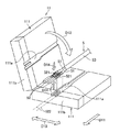
5 ツイストケーブル
6 コネクタハウジング
11 保持部
12 移動部
13 距離測定部
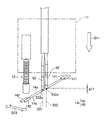
14 通過検知部
14a センサ光
15 出力部
16 ハウジング保持部
16a 挿入口
17 電線色検知部
18 制御部
19 入力部
20 圧力測定部
51 電線
52 コネクタ端子
53 最外被覆部分
61 端子収容室
111 保持板
111a 保持溝
111b 挟持部
131 直進部
132 受け部
141 発光部
142 受光部
521 圧着部
522 進路
522a 目標点
611 ランス
612 壁
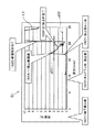
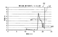
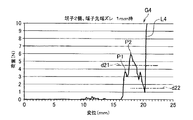
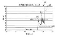
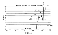
d11,d21,d31 第1閾値
d12,d22,d32 第2閾値
g11 ズレ量
D11 進行方向
D12 矢印
D13 配列方向
D14 方向
I11 情報
P1,P3,P5 第1ピーク
P2,P4,P6 第2ピーク
P7 第3ピーク
Claims (17)
- 各々が電線の端部に圧着接続された複数のコネクタ端子を、互いに平行に一列に配列して保持した保持部を、前記複数のコネクタ端子それぞれの先端を進行方向に向けて、前記保持部の移動距離を測定しながら直進移動させる移動工程と、
前記複数のコネクタ端子それぞれの進路を当該複数のコネクタ端子の配列方向に見た側面視で互いに一致する、当該進路における目標点の、前記複数のコネクタ端子それぞれの先端の通過を検知する通過検知工程と、
前記複数のコネクタ端子それぞれの先端について前記通過が検知されたときの前記移動距離に基づいて、前記複数のコネクタ端子それぞれの先端相互間のズレ量を求めるズレ量取得工程と、
を備えることを特徴とする端子ズレ量検知方法。 - 前記通過検知工程が、前記複数のコネクタ端子それぞれの前記進路における前記目標点を各々が通る複数のセンサ光それぞれを、前記複数のコネクタ端子それぞれの先端が遮ったことを以て前記通過を検知する工程であることを特徴とする請求項1に記載の端子ズレ量検知方法。
- 前記移動距離の測定が、前記保持部の移動につれて、当該保持部、又は当該保持部の進行方向の前方に配置された物体、によって押圧されることにより前記保持部の移動距離を測定する接触方式の計測器を用いて行われることを特徴とする請求項1又は2に記載の端子ズレ量検知方法。
- 各々が電線の端部に圧着接続された複数のコネクタ端子を、互いに平行に一列に配列して保持した保持部を、前記複数のコネクタ端子それぞれの先端を進行方向に向けて、前記保持部の移動距離を測定しながら直進移動させる移動工程と、
前記複数のコネクタ端子それぞれの進路を当該複数のコネクタ端子の配列方向に見た側面視で互いに一致する、当該進路における目標点の、前記複数のコネクタ端子それぞれの先端の通過を検知する通過検知工程と、
前記複数のコネクタ端子それぞれの先端について前記通過が検知されたときの前記移動距離に基づいて、前記複数のコネクタ端子それぞれの先端相互間のズレ量を求めるズレ量取得工程と、
前記ズレ量が所定の閾値未満の場合に、前記保持部を更に直進移動させて、前記複数のコネクタ端子それぞれの前記進路に複数の端子収容室が一対一に位置するように配置されたコネクタハウジングの前記複数の端子収容室に前記複数のコネクタ端子を同時挿入する挿入工程と、
を備えることを特徴とする端子挿入方法。 - 前記挿入工程が、前記移動距離を測定しつつ、その測定結果が、予め求めておいた、前記複数のコネクタ端子の全てを前記複数の端子収容室に挿入するに足る挿入完了距離に達するまで直進移動させる工程であることを特徴とする請求項4に記載の端子挿入方法。
- 前記挿入完了距離が、各々の先端が前記目標点に位置する前記複数のコネクタ端子の全てを前記複数の端子収容室に挿入するに足る前記保持部の移動距離であり、
前記挿入工程が、前記閾値未満の前記ズレ量が求められた場合に前記複数のコネクタ端子それぞれの先端のうち何れか1つの前記通過が検知されたときの前記保持部の位置をゼロ位置とし、当該ゼロ位置からの前記移動距離が、前記挿入完了距離に達するまで直進移動させる工程であることを特徴とする請求項5に記載の端子挿入方法。 - 前記コネクタハウジングが、前記保持部の進行方向の前方に配置されたハウジング保持
部によって保持されており、
前記移動距離の測定が、前記保持部の移動につれて、前記保持部又は前記ハウジング保持部によって押圧されることにより前記保持部の移動距離を測定する接触方式の計測器を用いて行われることを特徴とする請求項4〜6のうち何れか一項に記載の端子挿入方法。 - 各々が電線の端部に圧着接続された複数のコネクタ端子を、互いに平行に一列に配列して保持する保持部と、
前記保持部を、前記複数のコネクタ端子それぞれの先端を進行方向に向けて直進移動させる移動部と、
前記保持部の前記進行方向への移動距離を測定する距離測定部と、
前記複数のコネクタ端子それぞれの進路を当該複数のコネクタ端子の配列方向に見た側面視で互いに一致する、当該進路における目標点の、前記複数のコネクタ端子それぞれの先端の通過を検知する通過検知部と、
前記複数のコネクタ端子それぞれの先端について前記通過が検知されたときの前記移動距離に基づいて、前記複数のコネクタ端子それぞれの先端相互間のズレ量を求めるズレ量取得部と、
を備えたことを特徴とする端子ズレ量検知装置。 - 前記通過検知部が、前記複数のコネクタ端子それぞれの前記進路における前記目標点を各々が通る複数のセンサ光を発する発光部と、前記センサ光を受光する受光部と、を備え、当該受光部で前記センサ光が受光状態から非受光状態となったことを以て前記通過を検知するものであることを特徴とする請求項8に記載の端子ズレ量検知装置。
- 前記複数のコネクタ端子それぞれの先端について前記通過が検知されたときの前記移動距離を出力する出力部を更に備える、又は、当該出力部を前記ズレ量取得部に代えて備えることを特徴とする請求項8又は9に記載の端子ズレ量検知装置。
- 前記保持部が、前記複数のコネクタ端子それぞれにおける前記電線との圧着部を、前記進路及び前記配列方向の双方と交差する方向から挟持するものであることを特徴とする請求項8〜10のうち何れか一項に記載の端子ズレ量検知装置。
- 前記距離測定部が、前記保持部の移動につれて、当該保持部、又は当該保持部の進行方向の前方に配置された物体、によって押圧されることにより前記保持部の移動距離を測定する接触方式の計測器であることを特徴とする請求項8〜11のうち何れか一項に記載の端子ズレ量検知装置。
- 各々が電線の端部に圧着接続された複数のコネクタ端子を、互いに平行に一列に配列して保持する保持部と、
前記保持部を、前記複数のコネクタ端子それぞれの先端を進行方向に向けて直進移動させる移動部と、
前記保持部の前記進行方向への移動距離を測定する距離測定部と、
前記複数のコネクタ端子それぞれの進路を当該複数のコネクタ端子の配列方向に見た側面視で互いに一致する、当該進路における目標点の、前記複数のコネクタ端子それぞれの先端の通過を検知する通過検知部と、
コネクタハウジングを、前記複数のコネクタ端子それぞれの前記進路に複数の端子収容室が一対一に位置するように保持するハウジング保持部と、
前記複数のコネクタ端子それぞれの先端について前記通過が検知されたときの前記移動距離に基づいて、前記複数のコネクタ端子それぞれの先端相互間のズレ量を求めるズレ量取得部と、
前記ズレ量が所定の閾値未満であることを表す情報を取得する情報取得部と、
前記情報取得部における前記情報の取得を受けて、前記移動部に前記保持部を更に直進移動させて、前記複数の端子収容室に前記複数のコネクタ端子を同時挿入する挿入制御部と、を備えることを特徴とする端子挿入装置。 - 前記挿入制御部は、前記複数の端子収容室に前記複数のコネクタ端子を同時挿入するために前記保持部を更に直進移動させる際には、前記距離測定部での測定結果が、予め求めておいた、前記複数のコネクタ端子の全てを前記複数の端子収容室に挿入するに足る挿入完了距離に達するまで直進移動させるものであることを特徴とする請求項13に記載の端子挿入装置。
- 前記挿入完了距離が、各々の先端が前記目標点に位置する前記複数のコネクタ端子の全てを前記複数の端子収容室に挿入するに足る前記保持部の移動距離であり、
前記挿入制御部が、前記閾値未満の前記ズレ量が求められた場合に前記複数のコネクタ端子それぞれの先端のうち何れか1つの前記通過が検知されたときの前記距離測定部の測定結果をゼロにセットし、そのセット以降の前記距離測定部の測定結果が、前記挿入完了距離に達するまで直進移動させる工程であることを特徴とする請求項14に記載の端子挿入装置。 - 前記情報取得部が、前記ズレ量が前記閾値未満であるか否かの判定を行うことで前記情報を自己取得するものであることを特徴とする請求項13〜15のうち何れか一項に記載の端子挿入装置。
- 前記距離測定部が、前記保持部の移動につれて、当該保持部又は前記ハウジング保持部によって押圧されることにより前記保持部の移動距離を測定する接触方式の計測器であることを特徴とする請求項13〜16のうち何れか一項に記載の端子挿入装置。
Priority Applications (7)
| Application Number | Priority Date | Filing Date | Title |
|---|---|---|---|
| JP2017111656A JP6629263B2 (ja) | 2017-06-06 | 2017-06-06 | 端子ズレ量検知方法、端子挿入方法、端子ズレ量検知装置、及び端子挿入装置 |
| PT2018009882A PT2018225321B (pt) | 2017-06-06 | 2018-03-14 | Método de deteção de quantidade de deslocamento de terminal, método de inserção de terminal, dispositivo de deteção de quantidade de deslocamento de terminal e dispositivo de inserção de terminal |
| CN201880037740.9A CN110741515B (zh) | 2017-06-06 | 2018-03-14 | 端子错位量检测方法、端子插入方法、端子错位量检测装置以及端子插入装置 |
| PCT/JP2018/009882 WO2018225321A1 (ja) | 2017-06-06 | 2018-03-14 | 端子ズレ量検知方法、端子挿入方法、端子ズレ量検知装置、及び端子挿入装置 |
| MX2019014588A MX2019014588A (es) | 2017-06-06 | 2018-03-14 | Metodo de deteccion de cantidad de desplazamiento de la terminal, metodo de insercion de terminal, dispositivo de deteccion de cantidad de desplazamiento de la terminal, y dispositivo de insercion de terminal. |
| PT115951A PT115951B (pt) | 2017-06-06 | 2018-03-14 | Método de inserção de terminal e dispositivo de inserção de terminal |
| US16/668,365 US11223178B2 (en) | 2017-06-06 | 2019-10-30 | Terminal displacement amount detection method, terminal insertion method, terminal displacement amount detection device, and terminal insertion device |
Applications Claiming Priority (1)
| Application Number | Priority Date | Filing Date | Title |
|---|---|---|---|
| JP2017111656A JP6629263B2 (ja) | 2017-06-06 | 2017-06-06 | 端子ズレ量検知方法、端子挿入方法、端子ズレ量検知装置、及び端子挿入装置 |
Publications (2)
| Publication Number | Publication Date |
|---|---|
| JP2018206631A JP2018206631A (ja) | 2018-12-27 |
| JP6629263B2 true JP6629263B2 (ja) | 2020-01-15 |
Family
ID=64566694
Family Applications (1)
| Application Number | Title | Priority Date | Filing Date |
|---|---|---|---|
| JP2017111656A Active JP6629263B2 (ja) | 2017-06-06 | 2017-06-06 | 端子ズレ量検知方法、端子挿入方法、端子ズレ量検知装置、及び端子挿入装置 |
Country Status (6)
| Country | Link |
|---|---|
| US (1) | US11223178B2 (ja) |
| JP (1) | JP6629263B2 (ja) |
| CN (1) | CN110741515B (ja) |
| MX (1) | MX2019014588A (ja) |
| PT (2) | PT115951B (ja) |
| WO (1) | WO2018225321A1 (ja) |
Families Citing this family (1)
| Publication number | Priority date | Publication date | Assignee | Title |
|---|---|---|---|---|
| DE102019130288A1 (de) * | 2019-11-11 | 2021-05-12 | Metzner Holding GmbH | Vorrichtung, Verfahren und System zur Montage eines elektrischen Steckverbinders |
Family Cites Families (12)
| Publication number | Priority date | Publication date | Assignee | Title |
|---|---|---|---|---|
| JPH04132180A (ja) * | 1990-09-21 | 1992-05-06 | Fujikura Ltd | コネクタ |
| JPH11260526A (ja) * | 1998-03-06 | 1999-09-24 | Yazaki Corp | 電線付端子挿入装置 |
| MXPA05004904A (es) * | 2002-11-05 | 2005-07-22 | Yazaki Corp | Alojamiento de conector electrico, un metodo para marcar el alojamiento de conector electrico y un metodo para insertar una terminal de metal en el alojamiento de conector electrico. |
| JP4917418B2 (ja) * | 2006-12-14 | 2012-04-18 | タイコエレクトロニクスジャパン合同会社 | 端子挿入装置 |
| JP2010003432A (ja) * | 2008-06-18 | 2010-01-07 | Yazaki Corp | 多心電線の端末処理方法 |
| JP5051094B2 (ja) * | 2008-10-15 | 2012-10-17 | 住友電装株式会社 | 端子挿入不良判定方法 |
| JP2010165516A (ja) * | 2009-01-14 | 2010-07-29 | Sumitomo Wiring Syst Ltd | 端子半挿入検出機能付きコネクタ組立用装置 |
| JP5670667B2 (ja) * | 2010-07-22 | 2015-02-18 | 矢崎総業株式会社 | 端子及び端子のコネクタ装着方法 |
| JP5619587B2 (ja) * | 2010-12-10 | 2014-11-05 | 矢崎総業株式会社 | 端子挿入装置及び端子挿入方法 |
| JP5595572B2 (ja) * | 2013-09-27 | 2014-09-24 | 日本航空電子工業株式会社 | 電線ホルダ並びにそれを用いたハーネスの製造装置及び製造方法 |
| JP2015130304A (ja) * | 2014-01-09 | 2015-07-16 | 住友電装株式会社 | 電線処理装置及び配線モジュールの製造方法 |
| JP6078030B2 (ja) * | 2014-08-27 | 2017-02-08 | 矢崎総業株式会社 | コネクタハウジング位置検出装置及び位置検出方法 |
-
2017
- 2017-06-06 JP JP2017111656A patent/JP6629263B2/ja active Active
-
2018
- 2018-03-14 WO PCT/JP2018/009882 patent/WO2018225321A1/ja not_active Ceased
- 2018-03-14 MX MX2019014588A patent/MX2019014588A/es unknown
- 2018-03-14 PT PT115951A patent/PT115951B/pt active IP Right Grant
- 2018-03-14 CN CN201880037740.9A patent/CN110741515B/zh not_active Expired - Fee Related
- 2018-03-14 PT PT2018009882A patent/PT2018225321B/pt active IP Right Grant
-
2019
- 2019-10-30 US US16/668,365 patent/US11223178B2/en not_active Expired - Fee Related
Also Published As
| Publication number | Publication date |
|---|---|
| CN110741515B (zh) | 2021-04-06 |
| PT2018225321B (pt) | 2022-05-31 |
| PT115951B (pt) | 2022-01-25 |
| WO2018225321A1 (ja) | 2018-12-13 |
| US11223178B2 (en) | 2022-01-11 |
| PT115951A (pt) | 2021-06-03 |
| JP2018206631A (ja) | 2018-12-27 |
| MX2019014588A (es) | 2020-02-07 |
| CN110741515A (zh) | 2020-01-31 |
| US20200067253A1 (en) | 2020-02-27 |
Similar Documents
| Publication | Publication Date | Title |
|---|---|---|
| EP2689708B1 (en) | Endoscopic apparatus and measurement method | |
| CN105451630A (zh) | 插入系统以及对形状传感器的形状检测特性进行调整的方法 | |
| CN102735138B (zh) | 测量结构以及用于至少确定压接触头的导线压接体的压接高度的方法 | |
| JP5680005B2 (ja) | コネクタの嵌合状態を検査する検査方法および検査装置、並びにコネクタを有する電気機器の組立方法 | |
| US20120289778A1 (en) | Endoscope capable of displaying a scale for determination of the size of the target | |
| US20240235142A1 (en) | Electronic device assembly apparatus and electronic device assembly method | |
| US20120130168A1 (en) | Endoscope apparatus | |
| JP6629263B2 (ja) | 端子ズレ量検知方法、端子挿入方法、端子ズレ量検知装置、及び端子挿入装置 | |
| JP6590863B2 (ja) | 端子挿入方法及び端子挿入装置 | |
| US9240661B2 (en) | Apparatus for feeding crimp terminals on a carrier strip into a crimping press | |
| JP5170622B2 (ja) | 形状測定方法、プログラム、および形状測定装置 | |
| JP6150579B2 (ja) | 挿入装置 | |
| JP2011003503A (ja) | 電線と端子の圧着部評価方法および装置 | |
| US7362451B2 (en) | Sensor device | |
| JP6757369B2 (ja) | 導通検査治具および導通ピンの検査方法 | |
| JP7312663B2 (ja) | 線状物の作業位置決定方法、ロボットの制御方法、線状物の固定方法、線状物の作業位置決定装置および線状物把持システム | |
| JP4337103B2 (ja) | 電線装着装置、及び挿入構造 | |
| JP3991025B2 (ja) | 圧接端子の検査方法及び圧接端子の検査装置 | |
| JPS63225480A (ja) | マーク付きコネクタ | |
| JP2017009469A (ja) | 端子圧着不良検出装置 | |
| US20250236022A1 (en) | Electronic device assembly apparatus and electronic device assembly method | |
| JP4710647B2 (ja) | 端子測定装置 | |
| JP2007202272A (ja) | 電線端末処理装置における電線セット装置 | |
| JP4531680B2 (ja) | 電線処理機および電線処理機の光電センサ検出位置設定方法 | |
| KR20100003907A (ko) | 자동차의 전자제어장치 커넥터 핀 에러 진단 장치 |
Legal Events
| Date | Code | Title | Description |
|---|---|---|---|
| RD04 | Notification of resignation of power of attorney |
Free format text: JAPANESE INTERMEDIATE CODE: A7424 Effective date: 20180323 |
|
| A621 | Written request for application examination |
Free format text: JAPANESE INTERMEDIATE CODE: A621 Effective date: 20180810 |
|
| RD04 | Notification of resignation of power of attorney |
Free format text: JAPANESE INTERMEDIATE CODE: A7424 Effective date: 20180815 |
|
| A131 | Notification of reasons for refusal |
Free format text: JAPANESE INTERMEDIATE CODE: A131 Effective date: 20190903 |
|
| A521 | Request for written amendment filed |
Free format text: JAPANESE INTERMEDIATE CODE: A523 Effective date: 20191004 |
|
| TRDD | Decision of grant or rejection written | ||
| A01 | Written decision to grant a patent or to grant a registration (utility model) |
Free format text: JAPANESE INTERMEDIATE CODE: A01 Effective date: 20191126 |
|
| A61 | First payment of annual fees (during grant procedure) |
Free format text: JAPANESE INTERMEDIATE CODE: A61 Effective date: 20191204 |
|
| R150 | Certificate of patent or registration of utility model |
Ref document number: 6629263 Country of ref document: JP Free format text: JAPANESE INTERMEDIATE CODE: R150 |
|
| R250 | Receipt of annual fees |
Free format text: JAPANESE INTERMEDIATE CODE: R250 |
|
| S531 | Written request for registration of change of domicile |
Free format text: JAPANESE INTERMEDIATE CODE: R313531 |
|
| R350 | Written notification of registration of transfer |
Free format text: JAPANESE INTERMEDIATE CODE: R350 |
|
| R250 | Receipt of annual fees |
Free format text: JAPANESE INTERMEDIATE CODE: R250 |
|
| R250 | Receipt of annual fees |
Free format text: JAPANESE INTERMEDIATE CODE: R250 |