JP6697331B2 - Moving vehicle - Google Patents
Moving vehicle Download PDFInfo
- Publication number
- JP6697331B2 JP6697331B2 JP2016122738A JP2016122738A JP6697331B2 JP 6697331 B2 JP6697331 B2 JP 6697331B2 JP 2016122738 A JP2016122738 A JP 2016122738A JP 2016122738 A JP2016122738 A JP 2016122738A JP 6697331 B2 JP6697331 B2 JP 6697331B2
- Authority
- JP
- Japan
- Prior art keywords
- wheels
- electric
- moving vehicle
- axle
- chassis
- Prior art date
- Legal status (The legal status is an assumption and is not a legal conclusion. Google has not performed a legal analysis and makes no representation as to the accuracy of the status listed.)
- Active
Links
Images






Classifications
-
- B—PERFORMING OPERATIONS; TRANSPORTING
- B60—VEHICLES IN GENERAL
- B60L—PROPULSION OF ELECTRICALLY-PROPELLED VEHICLES; SUPPLYING ELECTRIC POWER FOR AUXILIARY EQUIPMENT OF ELECTRICALLY-PROPELLED VEHICLES; ELECTRODYNAMIC BRAKE SYSTEMS FOR VEHICLES IN GENERAL; MAGNETIC SUSPENSION OR LEVITATION FOR VEHICLES; MONITORING OPERATING VARIABLES OF ELECTRICALLY-PROPELLED VEHICLES; ELECTRIC SAFETY DEVICES FOR ELECTRICALLY-PROPELLED VEHICLES
- B60L50/00—Electric propulsion with power supplied within the vehicle
- B60L50/50—Electric propulsion with power supplied within the vehicle using propulsion power supplied by batteries or fuel cells
-
- B—PERFORMING OPERATIONS; TRANSPORTING
- B60—VEHICLES IN GENERAL
- B60R—VEHICLES, VEHICLE FITTINGS, OR VEHICLE PARTS, NOT OTHERWISE PROVIDED FOR
- B60R11/00—Arrangements for holding or mounting articles, not otherwise provided for
- B60R11/04—Mounting of cameras operative during drive; Arrangement of controls thereof relative to the vehicle
-
- B—PERFORMING OPERATIONS; TRANSPORTING
- B62—LAND VEHICLES FOR TRAVELLING OTHERWISE THAN ON RAILS
- B62D—MOTOR VEHICLES; TRAILERS
- B62D11/00—Steering non-deflectable wheels; Steering endless tracks or the like
- B62D11/02—Steering non-deflectable wheels; Steering endless tracks or the like by differentially driving ground-engaging elements on opposite vehicle sides
- B62D11/04—Steering non-deflectable wheels; Steering endless tracks or the like by differentially driving ground-engaging elements on opposite vehicle sides by means of separate power sources
-
- B—PERFORMING OPERATIONS; TRANSPORTING
- B60—VEHICLES IN GENERAL
- B60R—VEHICLES, VEHICLE FITTINGS, OR VEHICLE PARTS, NOT OTHERWISE PROVIDED FOR
- B60R11/00—Arrangements for holding or mounting articles, not otherwise provided for
- B60R2011/0001—Arrangements for holding or mounting articles, not otherwise provided for characterised by position
- B60R2011/004—Arrangements for holding or mounting articles, not otherwise provided for characterised by position outside the vehicle
-
- B—PERFORMING OPERATIONS; TRANSPORTING
- B60—VEHICLES IN GENERAL
- B60R—VEHICLES, VEHICLE FITTINGS, OR VEHICLE PARTS, NOT OTHERWISE PROVIDED FOR
- B60R11/00—Arrangements for holding or mounting articles, not otherwise provided for
- B60R2011/0042—Arrangements for holding or mounting articles, not otherwise provided for characterised by mounting means
- B60R2011/008—Adjustable or movable supports
-
- Y—GENERAL TAGGING OF NEW TECHNOLOGICAL DEVELOPMENTS; GENERAL TAGGING OF CROSS-SECTIONAL TECHNOLOGIES SPANNING OVER SEVERAL SECTIONS OF THE IPC; TECHNICAL SUBJECTS COVERED BY FORMER USPC CROSS-REFERENCE ART COLLECTIONS [XRACs] AND DIGESTS
- Y02—TECHNOLOGIES OR APPLICATIONS FOR MITIGATION OR ADAPTATION AGAINST CLIMATE CHANGE
- Y02T—CLIMATE CHANGE MITIGATION TECHNOLOGIES RELATED TO TRANSPORTATION
- Y02T10/00—Road transport of goods or passengers
- Y02T10/60—Other road transportation technologies with climate change mitigation effect
- Y02T10/70—Energy storage systems for electromobility, e.g. batteries
Landscapes
- Engineering & Computer Science (AREA)
- Mechanical Engineering (AREA)
- Transportation (AREA)
- Sustainable Development (AREA)
- Sustainable Energy (AREA)
- Power Engineering (AREA)
- Life Sciences & Earth Sciences (AREA)
- Chemical & Material Sciences (AREA)
- Combustion & Propulsion (AREA)
- Arrangement Or Mounting Of Propulsion Units For Vehicles (AREA)
- Manipulator (AREA)
- Fittings On The Vehicle Exterior For Carrying Loads, And Devices For Holding Or Mounting Articles (AREA)
- Electric Propulsion And Braking For Vehicles (AREA)
Description
本発明は、移動車両に関し、詳しくは、監視対象物を撮影する撮像部を備えた移動車両に関する。 The present invention relates to a moving vehicle, and more particularly, to a moving vehicle including an image capturing unit that captures a monitored object.
今日、荷物を搬送する搬送用ロボットや、建物内および建物周辺や所定の敷地内の状況を監視する監視用ロボットなど、自律的に移動する自律走行型車両が利用されている。また、地震、津波、土砂崩れ等の被災地での被災者の探索、あるいは事故が発生した工場、発電所などの内部の情報収集といった危険地域における活動にも、カメラ、各種センサ、アーム、ブーム等が搭載された自律走行型車両が利用される場合がある(例えば、特許文献1参照)。 2. Description of the Related Art Today, autonomous traveling vehicles that move autonomously are used, such as a transport robot that transports luggage, and a monitoring robot that monitors conditions inside a building, the vicinity of the building, and a predetermined site. In addition, cameras, various sensors, arms, booms, etc. can be used for activities in dangerous areas such as searching for victims in disaster areas such as earthquakes, tsunamis, and landslides, or collecting internal information such as factories and power plants where accidents occurred. There is a case where an autonomous vehicle equipped with is used (for example, refer to Patent Document 1).
このような従来の自律走行型車両は、走行すべき領域の地図情報と移動経路情報とを予め記憶し、カメラ、距離画像センサ、GPS(Global Positioning System)から取得し
た情報を利用して、障害物を避けながら、所定の経路を走行する。
Such a conventional autonomous vehicle stores the map information of the area to be traveled and the travel route information in advance, and utilizes the information acquired from the camera, the distance image sensor, and the GPS (Global Positioning System) to make an obstacle. Run on a designated route while avoiding objects.
カメラを搭載した自律走行型車両では、旋回する際に振動によって画像ブレが大きくなって画像を認識できなくなる場合があるため、画像ブレを抑えるためにカメラ取付位置等に振動吸収部材を設けている。 In an autonomous vehicle equipped with a camera, when the vehicle turns, the image blur may increase due to the vibration and the image may not be recognized. Therefore, a vibration absorbing member is provided at the camera mounting position or the like to suppress the image blur. ..
しかしながら、大きな振動から小さな振動まで全てに効果的な画像ブレ抑制構造とすると複雑になり高コストとなる。特に、カメラを昇降させるブームを有する自律走行型車両の場合、自律走行型車両の旋回時にはブームが揺れて画像ブレが大きくなる。 However, if the image blur suppression structure is effective for all of large vibrations to small vibrations, the structure becomes complicated and the cost becomes high. In particular, in the case of an autonomous traveling type vehicle having a boom that raises and lowers a camera, the boom shakes and the image blur increases when the autonomous traveling type vehicle turns.
本発明は、このような課題に鑑みなされたものであり、簡素な構成で画像ブレを効果的に抑えることができる移動車両を提供することを目的とする。 The present invention has been made in view of these problems, and an object thereof is to provide a moving vehicle that can effectively suppress image blur with a simple configuration.
かくして、本発明によれば、走行可能な電動車台部と、この電動車台部上に設けられた撮像部とを備え、
前記電動車台部は、車台本体と、この車台本体の前後に左右一対で設けられた複数の車輪と、複数の車輪のうち少なくとも前後一方側の左右一対の車輪を個別に回転駆動する2つの電動モータと、2つの電動モータに電力を供給するバッテリとを備え、
前記電動モータにて回転駆動される左右一対の車輪が同一の車軸線上に配置されており、
前記撮像部は、平面的に視て、前記電動モータにて回転駆動される左右一対の車輪間の前記車軸線上の中間点を中心としかつ前後の車輪の車軸線間の距離よりも短い所定半径を有する円形領域内に配置されている移動車両が提供される。
Thus, according to the present invention, it is possible to provide a movable electric chassis part and an imaging unit provided on the electric chassis part,
The electric chassis part includes a chassis main body, a plurality of left and right wheels provided in front and rear of the chassis main body, and two electric motors that individually rotate and drive at least one front and rear left and right pair of wheels of the plurality of wheels. A motor and a battery supplying electric power to the two electric motors,
A pair of left and right wheels rotationally driven by the electric motor are arranged on the same axle line,
The imaging unit, when viewed in plan, has a predetermined radius centered on an intermediate point on the axle between the pair of left and right wheels rotationally driven by the electric motor and shorter than a distance between axles of front and rear wheels. There is provided a moving vehicle arranged in a circular area having
本発明の移動車両は、複数の車輪のうち少なくとも前後一方側の左右一対の車輪を個別に回転制御して前進、後退、左旋回、右旋回および定置旋回することができる。旋回する場合、回転駆動する左右の車輪の回転速度差により左または右に旋回し、左右の車輪を相互に逆回転させることにより定置旋回する。
このとき、例えば、左右の前輪は回転力が伝達される駆動輪であり、左右の後輪は回転力が伝達されない従動輪である場合、ステアリング機構を有していないと、左に旋回すると左の後輪は左の前輪よりも大きい曲率半径で移動し、右に旋回すると右の後輪は右の前輪よりも大きい曲率半径で移動することになる。
したがって、撮像部が、平面的に視て、回転駆動される前後一方側の左右の車輪間の同一車軸線上の中間点を中心としかつ前後の車輪の車軸線間の距離よりも短い所定半径を有する円形領域内に配置されていることにより、回転駆動されない前後他方側の左右の車輪間の同一車軸線上の中間点付近に配置される場合と比べて、車両旋回時に小さい曲率半径で撮像部が旋回できる。
この結果、車両旋回時の撮像部の旋回速度および揺れが抑えられるため、特別な振動吸収部材や振動吸収機構等を用いることなく簡素な構成でありながら画像ブレを小さく抑えることができる。また、撮像部が電動車台部よりも水平方向外方へ突出することがないため、移動車両の走行時に障害物に撮像部を衝突させ難くすることができる。
The moving vehicle of the present invention can individually control the rotation of at least a pair of left and right wheels on the front and rear sides of the plurality of wheels to perform forward, backward, left turn, right turn, and stationary turn. When turning, the vehicle turns left or right due to the difference in rotational speed between the left and right wheels that are rotationally driven, and the left and right wheels rotate in opposite directions to make a fixed turn.
At this time, for example, when the left and right front wheels are drive wheels to which rotational force is transmitted and the left and right rear wheels are driven wheels to which rotational force is not transmitted, if the vehicle does not have a steering mechanism, turning to the left will cause The rear wheel moves with a larger radius of curvature than the left front wheel, and when turning right, the right rear wheel moves with a larger radius of curvature than the right front wheel.
Therefore, in a plan view, the imaging unit has a predetermined radius that is centered on the midpoint on the same axle between the left and right wheels on the front and rear sides that are rotationally driven and that is shorter than the distance between the axles of the front and rear wheels. By being arranged in a circular area that has, compared with the case where it is arranged near the midpoint on the same axle line between the left and right wheels on the other side of the front and rear that are not rotationally driven, the imaging unit has a smaller radius of curvature when turning the vehicle. You can turn.
As a result, the turning speed and shaking of the image pickup unit during turning of the vehicle can be suppressed, so that it is possible to suppress image blurring with a simple configuration without using a special vibration absorbing member or a vibration absorbing mechanism. Further, since the image pickup unit does not project outward in the horizontal direction from the electric chassis part, it is possible to make the image pickup unit less likely to collide with an obstacle when the moving vehicle is traveling.
本発明の移動車両は、走行可能な電動車台部と、この電動車台部上に設けられた撮像部とを備え、
前記電動車台部は、車台本体と、この車台本体の前後に左右一対で設けられた複数の車輪と、複数の車輪のうち少なくとも前後一方側の左右一対の車輪を個別に回転駆動する2つの電動モータと、2つの電動モータに電力を供給するバッテリとを備え、
前記電動モータにて回転駆動される左右一対の車輪が同一の車軸線上に配置されており、
前記撮像部は、平面的に視て、前記電動モータにて回転駆動される左右一対の車輪間の前記車軸線上の中間点を中心としかつ前後の車輪の車軸線間の距離よりも短い所定半径を有する円形領域内に配置されている。
ここで、車輪には、タイヤ付きホール、オムニホイールおよびメカナムホイール等が含まれる。
A mobile vehicle of the present invention includes an electric undercarriage portion capable of traveling, and an imaging portion provided on the electric undercarriage portion,
The electric chassis part includes a chassis main body, a plurality of left and right wheels provided in front and rear of the chassis main body, and two electric motors that individually rotate and drive at least one front and rear left and right pair of wheels of the plurality of wheels. A motor and a battery supplying electric power to the two electric motors,
A pair of left and right wheels rotationally driven by the electric motor are arranged on the same axle line,
The imaging unit, when viewed in plan, has a predetermined radius centered on an intermediate point on the axle between the pair of left and right wheels rotationally driven by the electric motor and shorter than a distance between axles of front and rear wheels. Are arranged in a circular area having.
Here, the wheel includes a hole with a tire, an omni wheel, a mecanum wheel, and the like.
本発明の移動車両は、次のように構成されてもよく、それらが適宜組み合わされてもよい。
(1)前記所定半径は、前記中間点から平面的に視た前記電動車台部の外周端部までの距離と等しくまたは短く設定されていてもよい。
このようにすれば、撮像部が電動車台部よりも水平方向外方へ突出することがないため、移動車両の走行時に障害物を衝突させ難くすることができる。
The mobile vehicle of the present invention may be configured as follows and may be appropriately combined.
(1) The predetermined radius may be set to be equal to or shorter than the distance from the intermediate point to the outer peripheral end of the electric chassis part when seen in a plan view.
With this configuration, the image pickup unit does not project outward in the horizontal direction from the electric chassis part, and thus it is possible to make it difficult for an obstacle to collide when the moving vehicle travels.
(2)前記撮像部は、前記中間点を通り前記車軸線と直交する前後方向の中心線上および前記車軸線上にコーナー部が配置されかつ前記円形領域内に収まる矩形領域内に配置されてもよい。
換言すると、前記円形領域内に収まる前記矩形領域は、回転駆動する左右の前輪の接地中心点と、前記中間点を通り前記車軸線と直交する前後方向の中心線とに45°の角度で交わる四辺を有する正方形の領域であってもよい。
このようにすれば、電動車台部上に撮像部を昇降させる昇降機構部を設けた場合に、上昇した撮像部が矩形領域内に配置されていることから、上昇位置からでも安定した画像の取得が可能となる。
(2) The image pickup unit may be arranged in a rectangular area having a corner portion on the center line in the front-rear direction passing through the intermediate point and orthogonal to the axle line and on the axle line, and within the circular region. ..
In other words, the rectangular area that fits within the circular area intersects the ground contact center points of the left and right front wheels that are rotationally driven and the center line in the front-rear direction that passes through the intermediate point and is orthogonal to the axle line at an angle of 45 °. It may be a square area having four sides.
With this configuration, when the elevating mechanism section that elevates and lowers the imaging section is provided on the electric chassis part, since the ascended imaging section is arranged in the rectangular area, stable image acquisition is possible even from the ascended position. Is possible.
(3)前記電動車台部の定置旋回中心点が、前記電動モータにて回転駆動される左右の車輪間の前記車軸線上の中間点であってもよい。
このようにすれば、撮像部が配置される円形または矩形領域の中心が定置旋回中心点と一致するため、移動車両が定置旋回するときに撮像部が旋回する曲率半径をさらに小さく抑えることができる。この結果、定置旋回時の撮像部の画像ブレをさらに抑えることができ、特に、電動車台部上に撮像部を昇降させる昇降機構部を設けた場合の上昇位置からの撮影に効果的となる。
(3) The stationary turning center point of the electric chassis part may be an intermediate point on the axle line between the left and right wheels rotationally driven by the electric motor.
With this configuration, the center of the circular or rectangular area in which the imaging unit is arranged coincides with the stationary turning center point, so that it is possible to further reduce the radius of curvature at which the imaging unit turns when the moving vehicle makes the stationary turning. .. As a result, it is possible to further suppress the image blurring of the image pickup unit at the time of stationary turning, and it is particularly effective for photographing from a raised position when an elevating mechanism unit for raising and lowering the image pickup unit is provided on the electric chassis part.
(4)前記電動車台部は、右側の前後の車輪を接続する右側動力伝達機構と、左側の前後の車輪を接続する左側動力伝達機構とをさらに備え、
前記電動車台部の定置旋回中心点が、左右の前輪および左右の後輪の接地中心点で囲まれた矩形エリアの中心点であってもよい。
このようにすれば、平面的に視て、電動車台部の中心または中心付近を定置旋回中心点とし、円形または矩形領域内に定置旋回中心点を配置し、撮像部を定置旋回中心点上またはその付近に配置することができる。この構成は、電動車台部の中心または中心付近で撮像部を昇降させて画像ブレを抑えた撮影を行う移動車両に適している。
(4) The electric undercarriage portion further includes a right power transmission mechanism that connects right and front wheels to each other, and a left power transmission mechanism that connects left and front wheels to each other.
The stationary turning center point of the electric chassis part may be a center point of a rectangular area surrounded by the grounding center points of the left and right front wheels and the left and right rear wheels.
With this configuration, when viewed in a plan view, the center or the vicinity of the electric chassis part is set as the fixed turning center point, the fixed turning center point is arranged in a circular or rectangular area, and the imaging unit is set on the fixed turning center point or It can be placed near it. This configuration is suitable for a moving vehicle that performs image capturing while suppressing image blur by moving the image capturing unit up and down at or near the center of the electric chassis part.
(5)前記電動モータにて回転駆動される左右の車輪が前輪であり、
左右の後輪が、ホイール本体と、このホイール本体の外周部に設けられた複数のローラーとを有するローラー付きホイールであってもよい。
ここで、ローラー付きホイールとは、ホイール本体の車軸線に対して各ローラーの回転軸心の角度が90°であるオムニホイール(登録商標)と、ホイール本体の車軸線に対して各ローラーの回転軸心の角度が45°であるメカナムホイールとが含まれる。
このようにすれば、前記(2)および(3)の構成の移動車両において、定置旋回時に後輪をスムーズに移動させることができ、画像ブレをより一層抑えることができる。
(5) The left and right wheels that are rotationally driven by the electric motor are front wheels,
The left and right rear wheels may be a wheel with rollers having a wheel body and a plurality of rollers provided on the outer peripheral portion of the wheel body.
Here, the wheel with rollers means an omni wheel (registered trademark) in which the angle of the rotation axis of each roller is 90 ° with respect to the axle of the wheel body, and the rotation of each roller with respect to the axle of the wheel body. And a mecanum wheel having an axis angle of 45 °.
With this configuration, in the moving vehicle having the configurations (2) and (3), the rear wheels can be smoothly moved during stationary turning, and image blur can be further suppressed.
(6)前記撮像部は、平面的に視て、前記中間点を通り前記車軸線と直交する前後方向の中心線上に配置されてもよい。
このようにすれば、移動車両の定置旋回を含む左旋回と右旋回において同等の画像ブレ抑制効果を得ることができる。
(6) The imaging unit may be arranged on a center line in the front-rear direction that passes through the intermediate point and is orthogonal to the axle line when seen in a plan view.
By doing so, it is possible to obtain the same image blur suppression effect in the left turn and the right turn including the stationary turn of the moving vehicle.
(7)前記電動モータにて回転駆動される左右の車輪が前輪であり、
前記撮像部は、前記左右の前輪の車軸線の中間点よりも前方に配置されてもよい。
このようにすれば、監視しやすい前方中央位置に撮像部を配置することができる。
(7) The left and right wheels that are rotationally driven by the electric motor are front wheels,
The image capturing unit may be disposed in front of an intermediate point of the axle lines of the left and right front wheels.
With this configuration, the imaging unit can be arranged at the front center position where it is easy to monitor.
(8)前記電動車台部上に設けられて前記撮像部を昇降させる昇降機構部をさらに備え、
前記昇降機構部によって昇降する前記撮像部の平面的に視た移動範囲が前記円形領域内に収まるようにしてもよい。
このようにすれば、撮像部をより遠くまで監視できるよう上昇させた状態で電動車台部が旋回しても画像ブレを抑えることができる。
(8) Further comprising an elevating mechanism part provided on the electric chassis part for elevating the imaging part,
The moving range of the imaging unit that moves up and down by the elevating mechanism unit in plan view may be within the circular region.
With this configuration, image blurring can be suppressed even when the electric chassis part turns while the imaging unit is raised so that it can be monitored further.
(9)昇降機構部が、前記撮像部を電動車台部に対して上下および前後方向に移動させるよう構成されてもよい。
この場合、上下および前後方向に揺動するブームを有する平行リンク機構あるいは各種パンタグラフ機構を昇降機構部として用いることができる。
(9) The elevating mechanism unit may be configured to move the imaging unit in the up-down direction and the front-rear direction with respect to the electric chassis part.
In this case, a parallel link mechanism or a pantograph mechanism having a boom that swings vertically and longitudinally can be used as the lifting mechanism unit.
(10)昇降機構部は、平面的に視て、前記撮像部が前記車軸線上を跨いで移動できるように構成されてもよい。
この構成は、車軸線の中間点を定置旋回中心点とし、昇降機構部によって下降時に撮像部を前方へ移動させ上昇時に撮像部を後方へ移動させる移動車両に適しており、上昇時においても撮像部が定置旋回中心点付近に配置されるため定置旋回時の画像ブレを抑えて安定した画像を取得することができる。
(10) The elevating mechanism unit may be configured such that the imaging unit can move across the axle line when seen in a plan view.
This configuration is suitable for a mobile vehicle in which the midpoint of the axle is set as the fixed turning center point, and the lifting mechanism moves the imaging part forward when descending and moves the imaging part backward when ascending. Since the part is arranged near the center point of stationary rotation, it is possible to suppress image blur during stationary rotation and acquire a stable image.
(11)昇降機構部は、前記車台本体上に固定される前後方向に延びる台枠と、前記台枠の後端部に左右軸心廻りに揺動可能に設けられたブームとを有するリンク機構であり、
前記台枠は、前端部上に下降した前記ブームを支持する支持部を有し、
前記支持部は、前記電動モータにて回転駆動される左右の車輪の車軸線上に配置されてもよい。
このようにすれば、定置旋回時における下降状態の撮像部の揺れを抑えて安定して支持することができる。
(11) The lifting mechanism unit includes a link mechanism having an underframe fixed to the chassis body and extending in the front-rear direction, and a boom provided at a rear end portion of the underframe so as to be swingable about a left-right axis. And
The underframe has a support portion that supports the boom lowered to the front end portion,
The support may be arranged on the axles of the left and right wheels that are rotationally driven by the electric motor.
By doing so, it is possible to suppress the shaking of the imaging unit in the lowered state during stationary rotation and to stably support the imaging unit.
(12)昇降機構部が、撮像部を電動車台部に対して上下方向にのみ移動させるよう構成されてもよい。
このようにすれば、菱形あるいは枠交差形のパンタグラフ機構を昇降機構部として用いることができる。
(12) The elevating mechanism unit may be configured to move the imaging unit only in the vertical direction with respect to the electric chassis part.
With this configuration, a diamond-shaped or frame-intersecting pantograph mechanism can be used as the lifting mechanism unit.
(13)前記電動モータにて回転駆動される左右一対の車輪が、駆動軸を介して前記電動車台部に取り付けられた車輪本体と、車輪本体の外周部に取り付けられて空気を充填されたタイヤとをそれぞれ有してもよい。
このようにすれば、移動車両の走行時において、左右の駆動輪のタイヤによって振動を吸収することができるため、左右の駆動輪に近い位置に配置された撮像部の画像ブレをより小さく抑えることができる。
(13) A wheel main body in which a pair of left and right wheels rotationally driven by the electric motor are attached to the electric chassis part via a drive shaft, and a tire attached to the outer peripheral portion of the wheel main body and filled with air. And may have respectively.
With this configuration, the vibrations of the left and right drive wheels can be absorbed when the moving vehicle is running, so that the image blur of the image pickup unit located near the left and right drive wheels can be further suppressed. You can
(14)移動車両が自律走行型移動車両であってもよい。
このようにすれば、移動車両を無線または有線によってオペレータが遠隔操作する、あるいはオペレータが移動車両に搭乗することなく、自律的に走行および監視を行うことができる。
(14) The moving vehicle may be an autonomous traveling type moving vehicle.
In this way, the traveling vehicle can be autonomously run and monitored without the operator remotely controlling the traveling vehicle wirelessly or by wire, or without the operator boarding the traveling vehicle.
以下、図面を参照しながら本発明の移動車両の実施形態について詳説する。なお、後述の実施形態では自律走行型移動車両の場合を例示するが、本発明の移動車両は自律走行型に限定されるものではなく、無線または有線による遠隔操作型、オペレータ搭乗型等の移動車両に適用可能である。 Hereinafter, an embodiment of a mobile vehicle of the present invention will be described in detail with reference to the drawings. In the embodiments described below, the case of an autonomous traveling type moving vehicle is illustrated, but the moving vehicle of the present invention is not limited to the autonomous traveling type, and it may be a wireless or wired remote control type, an operator boarding type or the like. It is applicable to vehicles.
(実施形態1)
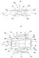
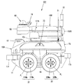
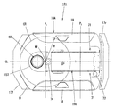
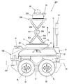
図1は本発明の移動車両の実施形態1における電動車台部の概略構成を説明する図であって、(A)は左側面図であり、(B)は(A)のB−B線矢視断面図である。また、図2は実施形態1の移動車両を示す左側面図であり、図3は図2の移動車両を上方から視た平面図である。また、図4は実施形態1の移動車両における撮像部上昇状態を示す左側面図であり、図5は図4の移動車両を上方から視た平面図である。
(Embodiment 1)
FIG. 1 is a diagram illustrating a schematic configuration of an electric chassis part in a first embodiment of a moving vehicle of the present invention, (A) is a left side view, and (B) is a line BB arrow of (A). FIG. 2 is a left side view showing the moving vehicle of the first embodiment, and FIG. 3 is a plan view of the moving vehicle of FIG. 2 as viewed from above. Further, FIG. 4 is a left side view showing a raised state of the image pickup unit in the moving vehicle of the first embodiment, and FIG. 5 is a plan view of the moving vehicle of FIG.
実施形態1の移動車両1Aは、主として、電動車台部10Aと、電動車台部10A上に設けられた昇降機構部50と、昇降機構部50の先端部に設けられた撮像部としての監視カメラ60を備える。なお、実施形態1では、移動車両として、監視カメラ60を備える自律走行型監視車両の場合を例示する。
The moving
さらに詳しくは、電動車台部10Aの前端部上には距離検出部12が設けられ、電動車台部10Aの後端部上にはWi−Fiアンテナ71および警告灯72が設けられ、電動車台部10Aの左右側面および後端面にはCCDカメラ73が設けられ、昇降機構部50の先端部における撮像部60の後方位置にはGPSアンテナ74が設けられている。
More specifically, the
距離検出部12は、移動する前方領域や路面の状態を確認する機能を有し、光を出射する発光部と、光を受光する受光部と、前記前方空間の所定の複数の測点に向けて前記光が出射されるように、光の出射方向を走査させる走査制御部とを備える。
距離検出部12としては、所定の距離測定領域内の2次元空間または3次元空間に、レーザーを出射し、前記距離測定領域内の複数の測点における距離を測定するLIDAR(Light Detection and Ranging、あるいはLaser Imaging Detection and Ranging:ライダー)を用いることができる。
The
The
図示しない制御ユニットは、この移動車両1Aの有する走行機能や監視機能などを実行する部分であり、例えば制御部、人検知部、指示認識部、通信部、指示実行部、記憶部などから構成される。
The control unit (not shown) is a part that executes the traveling function and the monitoring function of the moving
この移動車両1Aは、走行すべき領域の地図情報と移動経路情報とを予め記憶し、監視カメラ60、距離検出部12およびGPS(Global Positioning System)から取得した情報を利用して、障害物を避けながら、所定の経路を走行するよう構成されている。
The moving
この際、移動車両1Aは、特に、監視カメラ60や距離検出部12等を利用して、指示者の姿勢を認識して、その姿勢に予め対応づけられた指示に基づいて、電動車台部10Aの進行方向前方の状態を確認しながら自走する。例えば、前方に、障害物や段差等が存在することを検出した場合には、障害物に衝突することなどを防止するために、静止、回転、後退、前進等の動作を行って進路を変更し、指示に対応する機能を実行する。
At this time, the moving
次に、主として図1(A)および(B)を参照しながら移動車両1Aの走行に関係する構成を説明する。なお、図1(A)において左側の前輪31および後輪32を2点差線で示している。
Next, a configuration relating to traveling of the moving
<電動車台部の説明>
電動車台部10Aは、車台本体11と、車台本体11の前後左右に設けられた4つの車輪と、4つの車輪のうち少なくとも前後一方側の左右一対の車輪を個別に回転駆動する2つの電動モータ41R、41Lと、2つの電動モータ41R、41Lに電力を供給するバッテリ40と、距離検出部12と、図示しない制御ユニットとを備える。
<Explanation of the electric chassis part>
The
実施形態1の場合、図1(A)および(B)に示すように、電動車台部10Aは矢印A方向に前進するため、矢印A側の左右の車輪が前輪21、31であり、残りの左右の車輪が後輪22、32であり、左右の前輪21、31が2つの電動モータ4RL、43Lにて個別に駆動制御される。
なお、図1(A)および(B)では単に電動車台部を構成する各構成部およびそれらの配置を説明するものであるため、図1(A)および(B)で示された電動車台部の各構成部の大きさや間隔等は図2および図3に示された電動車台部と必ずしも一致するものではない。
In the case of the first embodiment, as shown in FIGS. 1 (A) and 1 (B), the
1 (A) and 1 (B) simply describe the components and their arrangement that form the electric chassis part, the electric chassis part shown in FIGS. 1 (A) and 1 (B). The sizes, intervals, etc. of the respective constituent parts do not necessarily match those of the electric chassis part shown in FIGS. 2 and 3.
車台本体11において、前面13と後面14にはバンパー17f、17rが取り付けられると共に、右側面12Rと左側面12Lには帯状のカバー18が設置され、車台本体11の前後方向に沿って延びている。カバー18の下側には、前輪21、31および後輪22、32をそれぞれ回転支持する車軸21a、31aおよび車軸22a、32aが設けられている。
駆動輪である前輪21、31の車軸21a、31aは同一の第1軸心(前輪の車軸線)P1上に配置されると共に、従動輪である後輪22、32の車軸22a、32aは同一の第2軸心(後輪の車軸線)P2上に配置されている。
なお、各車軸21a、31a、22a、32aは、独立して回転可能となっている。
The
In addition, each
車台本体11の底面15の前輪側には、右側の前輪21を駆動するための電動モータ41Rと左側の前輪31を駆動するための電動モータ41Lとの2つのモータが設けられている。右側の電動モータ41Rのモータ軸42Rと右側の前輪21の車軸21aとの間には、動力伝達機構としてギアボックス43Rが設けられている。同様に、左側の電動モータ41Lのモータ軸42Lと左側の前輪31の車軸31aとの間には、動力伝達機構としてギアボックス43Lが設けられている。ここでは、2つの電動モータ41R、41Lは車台本体11の進行方向(矢印A方向)の中心線CLに対して左右対称となるように並列配置されており、ギアボックス43R、43Lもそれぞれ電動モータ41R、41Lの左右外側に配設されている。
Two motors, an
ギアボックス43R、43Lは、複数の歯車や軸などから構成され、電動モータからの動力をトルクや回転数、回転方向を変えて出力軸である車軸に伝達する組立部品であり、動力の伝達と遮断を切替えるクラッチを含んでいてもよい。なお、一対の後輪22、32はそれぞれ軸受44R、44Lによって軸支されており、軸受44R、44Lはそれぞれ車台本体11の底面15の右側面12R、左側面12Lに近接させて配設されている。
The
以上の構成により、進行方向右側の前輪21と左側の前輪31とは、独立して駆動することが可能となる。すなわち、右側の電動モータ41Rの動力はモータ軸42Rを介してギアボックス43Rに伝わり、ギアボックス43Rによって回転数、トルクあるいは回転方向が変更されて車軸21aに伝達される。そして、車軸21aの回転によって前輪21が回転する。左側の電動モータ41Lからの前輪31への動力の伝達については上記した右側の動作と同様である。
With the above configuration, the
右と左の電動モータ41R、41Lの回転数が同じである場合、各ギアボックス43R、43Lのギア比(減速比)を同じにすれば、移動車両1Aは前進あるいは後進を行うことになる。移動車両1Aの速度を変更する場合は、各ギアボックス43R、43Lのギア比を同じ値に維持しつつ変化させればよい。
When the rotation speeds of the right and left
また、進行方向を変える場合は、各ギアボックス43R、43Lのギア比を変更して、右側の前輪21の回転数と左側の前輪31の回転数とに、回転差を持たせればよい。さらに、各ギアボックス43R、43Lからの出力の回転方向を変えることにより、右と左の車輪の回転方向を反対にかつ回転速度を同じにすることで、一対の前輪21、31の車軸線P1の中間点MPを定置旋回中心点とした定置旋回が可能になる。
When the traveling direction is changed, the gear ratio of each
移動車両1Aを定置旋回させる場合は、前後の車輪の角度を可変にするステアリング機構が設けられていないため、前後の車輪の間隔(ホイールベース)が大きいほど、車輪にかかる抵抗が大きくなり、旋回のために大きな駆動トルクが必要となる。しかし、各ギアボックス43R、43L内のギア比は可変にしているので、旋回時の車輪の回転数を下げるだけで車輪に大きなトルクを与えることができる。
When the moving
例えば、ギアボックス43R内のギア比として、モータ軸42R側のギアの歯数を10、中間ギアの歯数を20、車軸21b側のギアの歯数を40とした場合、車軸21bの回転数はモータ軸42Rの1/4の回転数となるが、4倍のトルクが得られる。そして、更に回転数が小さくなるようなギア比を選択することによって、より大きなトルクを得ることができるため、不整地や砂地などの車輪に係る抵抗が大きな路面であっても旋回が可能となる。
For example, if the number of gear teeth on the
ここで、車輪としては、特に限定されるものではなく、実施形態1の場合、各前後輪21、22、31、32は同じものが使用される。すなわち、図2に示すように、前輪31および後輪32は、車輪本体31a、32aと、車輪本体31a、32aの外周部に取り付けられて空気を充填されたタイヤ31b、32bとを有してなる。右側の前後輪21、22も同様である。
Here, the wheel is not particularly limited, and in the case of the first embodiment, the same front and
少なくとも駆動輪である右と左の前輪21、31が空気を充填されたタイヤを備えるものであることにより、移動車両1Aの凹凸路面の走行時において、前輪21、31のタイヤによって振動を吸収することができるため、前輪21、31に近い位置に配置された撮像部60の画像ブレをより小さく抑えることができる。
Since at least the right and left
また、この移動車両1Aは、モータ軸42R、42Lと車軸21a、31aとの間にギアボックス43R、43Lを設けているため、前輪21、31からの振動が直接モータ軸に伝わることがない。さらに、ギアボックス43R、43Lに動力の伝達と切り離し(遮断)を行うクラッチを設けておき、電動モータ41R、41Lの非通電時には、電動モータ41R、41L側と駆動軸となる車軸21a、31aとの間の動力伝達を遮断しておくことが望ましい。これにより、仮に停止時に車台本体11に力が加わり車輪が回転しても、電動モータ41R、41Lには回転が伝わらないため、電動モータ41R、41Lに逆起電力が発生することはなく、電動モータ41R、41Lの回路を損傷するおそれもない。
Further, since the moving
上記したように、車台本体11の底面15の前輪21、31側には2つの電動モータ41R、41Lを進行方向右側と左側に配置し、さらに各電動モータ41R、41Lのそれぞれの右側と左側にギアボックス43R、43Lを配置しているが、底面15の後輪22、32側には軸受44R、44Lを配置しているだけであるため、車台本体11の底面15には、その中央位置から例えば車体の後端までに亘って、広い収容スペース16を確保できる。
As described above, the two
各電動モータ41R,41Lは、例えばリチウムイオン電池などのバッテリ(充電池)40を動力源とし、バッテリ40を収容スペース16に設置する。具体的には、バッテリ40は、例えば直方体の外形をなし、図1(B)に示すように、底面15の略中央位置に載置することが可能である。また、車台本体11の後面14は例えば上面あるいは底面15に対して開閉可能に構成し、収容スペース16へのバッテリ40の出し入れを容易にすることが望ましい。これにより、長時間走行を実現させるための大容量のバッテリ40を車台本体11の収容スペース16に搭載可能になり、また、バッテリ40の交換、充電、点検などの作業は、後面14から容易に実施可能になる。さらに、バッテリ40を底面15に配置することができるため、車台本体11の重心が低く、安定した走行が可能な電動車両を得ることができる。
Each of the
<昇降機構部および撮像部の説明>
図2〜5に示すように、実施形態1の場合、昇降機構部50は、撮像部である監視カメラ60を電動車台部10Aに対して上下および前後方向に移動させるよう構成されている。
<Explanation of lifting mechanism section and imaging section>
As shown in FIGS. 2 to 5, in the case of the first embodiment, the elevating
さらに詳しく説明すると、昇降機構部50としては、上下および前後方向に揺動するブーム52を有するリンク機構、具体的には、平行リンク機構が用いられている。
すなわち、この昇降機構部50は、車台本体11上に固定される前後方向に延びる台枠51と、台枠51の後端部に左右軸心廻りに揺動可能に設けられた前記ブーム52と、ブーム52の先端に設けられた平衡部53と、台枠51内に設けられてブーム52を上下に揺動させる図示しない伸縮シリンダとを備える。
More specifically, as the elevating
That is, the
台枠51は、前端部上に下降したブーム52を支持する支持部51aを有すると共に、後端部にブーム52の基端部を枢支する枢着部51bを有している。
ブーム52は、主枠52aと、主枠52aに沿って設けられた平衡部支持ロッド52bとを有する。
The
The
主枠52aの基端部は、台枠51の枢着部51bに回転可能に枢着された第1基端軸f11に固定されると共に、主枠52aの先端部は平衡部53に第1先端軸f12を介して枢着されている。
平衡部支持ロッド52bの基端部は、台枠51の枢着部51bに枢着された第2基端軸f21に固定されると共に、平衡部支持ロッド52bの先端部は平衡部53に第2先端軸f22を介して枢着されている。
The base end portion of the
Proximal end of the balanced
図示しない伸縮シリンダとしては、電動式、油圧式あるいは空気圧式シリンダを用いることができる。
伸縮シリンダの基端部は台枠51または車台本体11に上下揺動可能に枢着され、伸縮シリンダの先端部は図示しないアームを介して第1基端軸f11に連結されている。このとき、伸縮シリンダの先端部はアームの一端に枢着され、アームの他端は第1基端軸f11に固定されている。
As the telescopic cylinder (not shown), an electric type, a hydraulic type or a pneumatic type cylinder can be used.
The base end portion of the telescopic cylinder is pivotally attached to the
平衡部53は、ブーム52が上下方向に揺動しても監視カメラ60およびGPSアンテナ74の正常な姿勢を安定的に保つ平衡装置である。
監視カメラ60は、特に限定されるものではなく、例えば、ドーム型カメラ(パンチルトズーム(PTZ)カメラを含む)、ボックス型カメラ、ハウジングカメラ、赤外線暗視カメラ、望遠カメラ等を用いることができ、電動車台部10Aの前方および左右の空間領域を撮影できるよう平衡部60上に設置されている。なお、移動車両1Aを屋外で使用する場合は監視カメラ60に防水機能が付加される。
The balancing
The
さらにドーム型カメラとしては、水平および垂直方向のレンズ画角が広いタイプ(例えば、水平180°程度、垂直90°程度)、高解像度タイプ(例えば、3840×2160ピクセル)、カラー撮影可能なタイプ、人を検知した場合にのみ撮影するタイプ、人を検知し顔をクローズアップして追跡するタイプ、暗闇での撮影が可能な赤外線暗視タイプ等を使用してもよい。 Further, as the dome type camera, a type having a wide horizontal and vertical lens field angle (for example, about 180 ° horizontally, about 90 ° vertically), a high resolution type (for example, 3840 × 2160 pixels), a type capable of color photographing, You may use the type which image | photographs only when a person is detected, the type which detects a person and tracks a face close-up, the infrared night vision type which can image | photograph in darkness, etc.
次に、昇降機後部50の動作について説明する。
図2および図3では昇降機構部50が下降した状態が示されており、このとき、伸縮シリンダは伸長している。昇降機構部50を上昇させる場合、伸縮シリンダを短縮させる。これにより、伸縮シリンダの先端部と枢着したアームが前方へ引き寄せられると共に、アームと第1基端軸f11と主枠52aとが上方(矢印E方向)へ一体的に揺動する。また、主枠52aが上方へ揺動することにより、平衡部53を介して主枠52aの先端部と連結した平衡部支持ロッド52bが上方(矢印E方向)へ持ち上げられる。
Next, the operation of the elevator
2 and 3 show the state where the elevating
このとき、主枠52aに対して平衡部支持ロッド52bが平行のまま位置ずれすることによって平衡部53の第2先端軸f22が平衡部支持ロッド52bの方へ引き寄せられるため、平衡部53およびその上に設置された監視カメラ60およびGPSアンテナ74の正常姿勢が下降位置から上昇位置まで保たれる。
また、伸縮シリンダを伸長していくと、ブーム52は前記と逆に動作して図4の上昇状態から図2の下降状態となる。
このように、昇降機構部50によって監視カメラ60は第1車軸線P1を跨いで前後に移動する。
At this time, the second tip axis f 22 of the balancing
Further, when the telescopic cylinder is extended, the
In this way, the raising and lowering
前記構成を有する昇降機構部50の平衡部53上に設置された監視カメラ60は、平面的に視て、電動車台部10Aの定置旋回中心点MP(一対の前輪21、31の車軸線P1上の中間点MP)を中心とする電動車台部10Aの内側領域内の円形CRの領域内に配置されている。
このとき、車両走行時に監視カメラ60が障害物に衝突しないよう、円形CRの半径Rは中間点MPから平面的に視た電動車台部10Aの外周端部までの距離よりも短く設定されている。具体的には、半径Rは、平面的に視て、前後の車軸線P1、P2間よりも短く、かつ定置旋回中心点MPから電動車台部10Aの右側面または左側面までの距離よりも短い。
The monitoring
At this time, the radius R of the circle CR is set to be shorter than the distance from the intermediate point MP to the outer peripheral end of the
なお、実施形態1の場合、図1(B)で示した一対の前輪21、31および一対の後輪22、32の4つの接地中心点G21、G31、G22、G32において、接地中心点G21、G22間(G31、G32間)の距離は450〜550mm程度であり、接地中心点G21、G31間(G22、G32間)の距離は650〜750mm程度であり、半径Rは300〜500mm程度である。また、下降位置の監視カメラ60の高さは850〜1050mm程度であり、上昇位置の監視カメラ60の高さは1650〜1900mm程度である。
In the case of the first embodiment, the ground contact is made at the four ground contact center points G 21 , G 31 , G 22 , and G 32 of the pair of
さらに、監視カメラ60は、定置旋回中心点MPを通る前後方向の中心線CL上に配置されている。この中心線CLは、円形CRの領域内における第1車軸線P1と中間点MPで直交する線である。これにより、移動車両1Aの左旋回時と右旋回時とで同等の画像ブレ抑制効果を得ることができる。
Further, the monitoring
また、図3に示した下降位置の監視カメラ60は中間点MP(定置旋回中心点MP)よりも前方に配置され、図5に示した上昇位置の監視カメラ60は中間点MPよりも後方に配置されるが、いずれも中間点MPを中心とする狭い円形CRの領域内にある。すなわち、昇降機構部50によって昇降する監視カメラ60の平面的に視た移動範囲が狭い円形CRの領域内に収まるため、下降位置にある監視カメラ60による周辺空間の撮影時は無論のこと、上昇位置にある監視カメラ60によって周辺空間を右または左へ旋回しながら撮影する際のブーム52の先端の監視カメラ60の揺れが抑えられて画像ブレが抑制される。なお、下降位置の監視カメラ60は、下降位置の昇降機構50のブーム52が支持部51aによって支持されることによっても旋回時の揺れが効果的に抑制される。
The descending
また、右と左の前輪21、31が等速度で相互に逆回転した場合、移動車両1Aは中間点MP(定置旋回中心点MP)を中心に定置旋回する。このとき、図5に示すように上昇位置にある監視カメラ60は定置旋回中心点MPに近い位置にあるため揺れが抑えられ、画像ブレも抑えられる。
Further, when the right and left
(実施形態2)
図6は本発明の移動車両の実施形態2における電動車台部の概略構成を説明する図であって、(A)は左側面図であり、(B)は(A)のB−B線矢視断面図である。また、図7は実施形態2の移動車両を示す平面図であり、図8は実施形態2の移動車両における撮像部上昇状態を示す平面図である。なお、図6〜8において、図1〜5中の要素と同様の要素には同一の符号を付している。
以下、実施形態2における実施形態1とは異なる点を主に説明する。
(Embodiment 2)
6A and 6B are diagrams illustrating the schematic configuration of the electric chassis part in the second embodiment of the mobile vehicle of the present invention, in which FIG. 6A is a left side view and FIG. 6B is a line BB arrow of FIG. FIG. Further, FIG. 7 is a plan view showing the moving vehicle of the second embodiment, and FIG. 8 is a plan view showing a rising state of the imaging unit in the moving vehicle of the second embodiment. 6 to 8, the same elements as those in FIGS. 1 to 5 are designated by the same reference numerals.
Hereinafter, points of the second embodiment different from the first embodiment will be mainly described.
実施形態2の移動車両1Bは、実施形態1の移動車両1Aにおける電動車台部10Aに右側の前後輪21、22を接続する右側動力伝達機構45Rと左側の前後輪31、32を接続する左側動力伝達機構45Lとが設けられてなる電動車台部10Bを備えると共に、この電動車台部10B上に実施形態1と同様の昇降機構部50を備えている。
すなわち、実施形態2の移動車両1Bは、右および左のそれぞれ一対の前輪21、31と後輪22、32は、動力伝達部材であるベルト23、33によって連動するように構成されており、その他の構成は実施形態1と同様である。
The moving
That is, in the moving
右側動力伝達機構45Rは具体的に次のように構成されている。
右側の前輪21の車軸21aにはプーリ21bが設けられ、後輪22の車軸22aにはプーリ22bが設けられる。また、前輪21のプーリ21bと後輪22のプーリ22bとの間には、例えばプーリ21b、22bの外周面に設けられた複数の溝と歯合する突起を内面側に設けたベルト23が巻架されている。
左側動力伝達機構45LもR同様に、左側の前輪31の車軸31aにはプーリ31bが設けられると共に、後輪32の車軸32aにはプーリ32bが設けられており、前輪31のプーリ31bと後輪32のプーリ32bとの間には、ベルト23と同様の構造を持つベルト33が巻架されている。
The right
A
Similarly to the left
したがって、右と左の前輪と後輪(21と22、31と32)は、ベルト(23、33)によって連結駆動されるので、一方の車輪を駆動すればよい。実施形態2では、前輪21、31を駆動する場合を例示している。一方の車輪を駆動輪とした場合に、他方の車輪は、動力伝達部材であるベルトによってスリップすることなく駆動される従動輪として機能する。
前輪と後輪とを連結駆動する動力伝達部材としては、プーリとこのプーリの外周面の複数の溝に歯合する突起を設けたベルトを用いるほか、例えば、スプロケットとこのスプロケットに歯合するチェーンを用いてもよい。さらに、スリップが許容できる場合は、摩擦の大きなプーリとベルトを動力伝達部材として用いてもよい。ただし、駆動輪と従動輪の回転数が同じとなるように動力伝達部材を構成する。
図6(A)と(B)では、前輪(21、31)が駆動輪に相当し、後輪(22、32)が従動輪に相当する。
Therefore, since the right and left front wheels and the rear wheels (21 and 22, 31 and 32) are connected and driven by the belts (23 and 33), one of the wheels may be driven. The second embodiment exemplifies a case where the
As a power transmission member for connecting and driving the front wheel and the rear wheel, a pulley and a belt provided with protrusions that mesh with a plurality of grooves on the outer peripheral surface of the pulley are used.For example, a sprocket and a chain that meshes with the sprocket are used. May be used. Furthermore, if slippage is acceptable, a pulley and a belt with large friction may be used as the power transmission member. However, the power transmission member is configured so that the driving wheels and the driven wheels have the same rotational speed.
In FIGS. 6A and 6B, the front wheels (21, 31) correspond to driving wheels and the rear wheels (22, 32) correspond to driven wheels.
以上の構成により、進行方向右側の前後輪21、22と、左側の前後輪31、32とは、独立して駆動することが可能となる。すなわち、右側の電動モータ41Rの動力はモータ軸42Rを介してギアボックス43Rに伝わり、ギアボックス43Rによって回転数、トルクあるいは回転方向が変更されて車軸21aに伝達される。そして、車軸21aの回転によって前輪21が回転するとともに、車軸21aの回転は、プーリ21b、ベルト23、および、プーリ22bを介して後軸22bに伝わり、後輪22を回転させることになる。左側の電動モータ41Lからの前輪31および後輪32への動力の伝達については上記した右側の動作と同様である。
With the above configuration, the front and
右と左の電動モータ41R、41Lの回転数が同じである場合、各ギアボックス43R、43Lのギア比(減速比)を同じにすれば、移動車両1は前進あるいは後進を行うことになる。移動車両1の速度を変更する場合は、各ギアボックス43R、43Lのギア比を同じ値に維持しつつ変化させればよい。
When the rotation speeds of the right and left
また、進行方向を変える場合は、各ギアボックス43R、43Lのギア比を変更して、右側の前輪21および後輪22の回転数と左側の前輪31および後輪32の回転数とに、回転差を持たせればよい。さらに、各ギアボックス43R、43Lからの出力の回転方向を変えることにより、右と左の車輪の回転方向を反対にかつ回転速度を同じにすることで、一対の前輪21、31および一対の後輪22、32の4つの接地中心点G21、G31、G22、G32で囲まれた矩形エリアの中心点CPを中心とした定置旋回が可能になる。なお、実施形態2の場合、車台本体11の中央部が前記中心点CPとほぼ一致するように設定される。
When the traveling direction is changed, the gear ratios of the
このように、右と左それぞれの前輪と後輪を動力伝達部材で連結し、前輪側に配置した2つの電動モータで駆動可能するようにして4輪を駆動しているので、後輪専用の電動モータ、さらに、この電動モータと後輪との間に必要な後輪専用のギアボックスを設ける必要がなく、後輪専用の電動モータやギアボックスのための設置スペースを削減することができる。 In this way, the right and left front wheels and the rear wheels are connected by the power transmission member, and the four wheels are driven so as to be driven by the two electric motors arranged on the front wheel side. Since it is not necessary to provide an electric motor and a gearbox dedicated to the rear wheels, which is required between the electric motor and the rear wheels, it is possible to reduce the installation space for the electric motor or gearbox dedicated to the rear wheels.
実施形態2の移動車両1Bによれば、図8に示すように、上昇位置の監視カメラ60は定置旋回中心点(中心点CP)のほぼ真上に配置されるため、定置旋回時に上昇位置の監視カメラ60の揺れおよび画像ブレが効果的に抑えられる。また、図7に示すように、下降位置の監視カメラ60は左右の前輪21、31の第1車軸線P1の中間点MPを中心とする前記円形CRの領域内に配置されるため、右の前後輪21、22と左の前後輪31、32との回転速度差によって右または左に旋回する際も下降位置の監視カメラ60の揺れおよび画像ブレが抑えられる。
According to the moving
(実施形態3)
図9は本発明の移動車両の実施形態3における電動車台部の概略構成を説明する図であって、(A)は左側面図であり、(B)は(A)のB−B線矢視断面図である。また、図10は実施形態3の移動車両を示す左側面図である。なお、図9および10において、図1〜8中の要素と同様の要素には同一の符号を付している。
以下、実施形態3における実施形態1および2とは異なる点を主に説明する。
(Embodiment 3)
9A and 9B are views for explaining the schematic configuration of the electric chassis part in the third embodiment of the moving vehicle of the present invention, FIG. 9A is a left side view, and FIG. 9B is a line BB arrow of FIG. FIG. FIG. 10 is a left side view showing the moving vehicle of the third embodiment. 9 and 10, the same elements as those in FIGS. 1 to 8 are designated by the same reference numerals.
Hereinafter, differences between the third embodiment and the first and second embodiments will be mainly described.
実施形態2の移動車両1B(図6(B)参照)の場合、各車輪21、22、31、32としてタイヤ付きホイールが用いられていたが、実施形態3の移動車両1Cの場合、左右の後輪122、132としてオムニホイール(登録商標)が用いられている。この場合、左右の前輪21、31の外面と左右の後輪122、132の外面が同一面上に揃うようにする。
なお、実施形態3において、その他の構成は実施形態2と同様である。
In the case of the moving
Note that the other configurations of the third embodiment are similar to those of the second embodiment.
左右の後輪122、132をオムニホイールとすることにより、電動車台部10Cの旋回時に、左右の後輪122、132は左右方向へスムーズに移動することができる。そのため、実施形態3の移動車両1Cは、左右の前輪21、31(タイヤ付きホイール)を相互に逆方向に同じ回転数で回転させると、前輪21、31の第1車軸線P1の中間点MPを中心にして低トルクでもスムーズに定置旋回することができる。
この実施形態3の移動車両1Cによれば、右側動力伝達機構45Rと左側動力伝達機構45Lとによって前輪21、31および後輪122、132を駆動させる駆動性が得られることに加え、監視カメラ60が配置される円形CRの領域(図7参照)の中心点MPを定置旋回中心点とするため、定置旋回時の画像ブレを小さく抑えることができる。
なお、実施形態3の移動車両1Cにおいて、左右の後輪122、132として、オムニホールの代わりにメカナムホイールを用いてもよい。
By making the left and right
According to the moving vehicle 1C of the third embodiment, in addition to the drivability of driving the
In the moving vehicle 1C of the third embodiment, mecanum wheels may be used as the left and right
(実施形態4)
図11は本発明の移動車両の実施形態4を示す平面図であり、図12は実施形態4の移動車両における撮像部上昇状態を示す平面図である。なお、図11および12において、図3および5中の要素と同様の要素には同一の符号を付している。
以下、実施形態4における実施形態1とは異なる点を主に説明する。
(Embodiment 4)
FIG. 11 is a plan view showing a fourth embodiment of the moving vehicle of the present invention, and FIG. 12 is a plan view showing a rising state of the image pickup unit in the moving vehicle of the fourth embodiment. 11 and 12, the same elements as those in FIGS. 3 and 5 are designated by the same reference numerals.
Hereinafter, differences from the first embodiment in the fourth embodiment will be mainly described.
実施形態1では、平面的に視て、監視カメラ60が下降と上昇のいずれの状態においても、駆動輪(前輪21、31)の車軸線P1の中間点MPを中心としかつ電動車台部10Aの内側領域に収まる円形CRの領域内に配置される場合を例示した。
これに対し、実施形態4の移動車両1Dでは、平面的に視て、監視カメラ60が下降と上昇のいずれの状態においても、駆動輪(前輪21、31)の車軸線P1の中間点MPを中心としかつ前記円形CRの領域に収まる矩形SQの領域内に配置される。そして、この矩形SQの領域は、回転駆動する左右の前輪21、31の接地中心点G21、G31と、前記中間点MPを通り車軸線P1と直交する前後方向の中心線CLとに45°の角度で交わる四辺を有する正方形の領域である。
なお、実施形態4におけるその他の構成は実施形態1と同様である。
In the first embodiment, when viewed in plan, the monitoring
On the other hand, in the moving
The rest of the configuration of the fourth embodiment is similar to that of the first embodiment.
このように監視カメラ60を駆動輪(前輪21、31)の車軸線P1の中間点MPを中心とする矩形SQの領域内に配置しても、監視カメラ60の移動範囲は下降と上昇のいずれの状態でも矩形SQの領域内に収まるため、移動車両1の旋回時の画像ブレが小さく抑えられる。
なお、実施形態2および3の移動車両1B、1Cにおいても、監視カメラ60を実施形態4と同様の矩形SQの領域内に配置するようにしてもよい。
Thus, even if the
In the moving
(実施形態5)
図13は本発明の移動車両の実施形態5を示す左側面図であり、図14は図13の移動車両を上方から視た平面図である。また、図15は実施形態5の移動車両における撮像部上昇状態を示す左側面図であり、図16は図15の移動車両を上方から視た平面図である。なお、図13〜16において、図2〜5中の要素と同様の要素には同一の符号を付している。
(Embodiment 5)
13 is a left side view showing Embodiment 5 of the moving vehicle of the present invention, and FIG. 14 is a plan view of the moving vehicle of FIG. 13 as seen from above. Further, FIG. 15 is a left side view showing an ascending state of the image pickup unit in the moving vehicle of the fifth embodiment, and FIG. 16 is a plan view of the moving vehicle of FIG. 13 to 16, the same elements as those in FIGS. 2 to 5 are designated by the same reference numerals.
実施形態5の移動車両101の実施形態1と異なる点は、昇降機構部150の構成であり、実施形態2におけるその他の構成は概ね実施形態1と同様である。
以下、実施形態5の実施形態1とは異なる点を主として説明する。
The moving
Hereinafter, differences between the fifth embodiment and the first embodiment will be mainly described.
図13および14に示すように、実施形態5の昇降機構部150としては、シングルアーム形のパンタグラフ機構が用いられている。
すなわち、この昇降機構部150は、車台本体11上に固定される前後方向に延びる台枠151と、台枠151の前端部に左右軸心廻りに揺動可能に設けられた第1ブーム152Aと、第1ブーム152Aの先端部に左右軸心廻りに揺動可能に設けられた第2ブーム152Bと、第1ブーム152Aと第2ブーム152Bとを接続するヒンジ部152Cと、第2ブーム152Bの先端に設けられた平衡部153と、台枠151内に設けられて第1ブーム152Aを上下に揺動させる図示しない伸縮シリンダとを備える。
As shown in FIGS. 13 and 14, a single-arm type pantograph mechanism is used as the elevating
That is, the
台枠151は、後端部に第1ブーム152Aの基端部を枢支する枢着部151bを有している。
第1ブーム152Aは、下第1枠152Aaと、下第1枠152Aaに沿って設けられた下第2枠152Abと、釣合ロッド152Acとを有する。
第2ブーム152Bは、上枠152Baと、上枠152Baに沿って設けられた平衡部支持ロッド152Bbとを有する。
The
The
The
下第1枠152Aaの基端部は、枢着部151bに回転可能に枢着された図示しない下側の第1基端軸に固定されると共に、下第1枠152Aaの先端部はヒンジ部152Cに下側の第1先端軸f112を介して枢着されている。
下第2枠152Abの基端部は、枢着部151bに回転可能に枢着された図示しない下側の第2基端軸に固定されると共に、下第2枠の先端部はヒンジ部152Cに下側の第2先端軸f114を介して枢着されている。
釣合ロッド152Acの基端部は、枢着部151bに回転可能に枢着された図示しない下側の第3基端軸に固定されると共に、第2釣合ロッド152Acの先端部は上枠152Baの図示しない折れ曲がった基端部に図示しない下側の第3先端軸を介して枢着されている。
The base end portion of the lower first frame 152Aa is fixed to a lower first base end shaft (not shown) that is rotatably pivotally attached to the
The base end portion of the lower second frame 152Ab is fixed to a lower second base end shaft (not shown) pivotally attached to the
The base end portion of the balance rod 152Ac is fixed to a lower third base end shaft (not shown) that is pivotally attached to the
上枠152Baの基端部は、枢着部151bに枢着された上側の第1基端軸f117に固定されると共に、上枠152Baの先端部は平衡部153に上側の第1先端軸f118を介して枢着されている。
平衡部支持ロッド152Bbの基端部は、枢着部151bに枢着された上側の第2基端軸f119に固定されると共に、平衡部支持ロッド152Bbの先端部は平衡部53に上側の第2先端軸f120を介して枢着されている。
The base end portion of the upper frame 152Ba is fixed to the upper first base end shaft f 117 pivotally attached to the
The base end portion of the balance portion support rod 152Bb is fixed to the upper second base end shaft f 119 pivotally attached to the
図示しない伸縮シリンダとしては、実施形態1と同様に、電動式、油圧式あるいは空気圧式シリンダを用いることができる。
伸縮シリンダの基端部は台枠151または車台本体11に上下揺動可能に枢着され、伸縮シリンダの先端部は図示しないアームを介して前記下側の第1基端軸に連結されている。このとき、伸縮シリンダの先端部はアームの一端に枢着され、アームの他端は前記下側の第1基端軸に固定されている。
As the telescopic cylinder (not shown), an electric, hydraulic, or pneumatic cylinder can be used as in the first embodiment.
The base end portion of the telescopic cylinder is pivotally attached to the
平衡部153は、実施形態1と同様に、第1および第2ブーム152A、152Bが上下方向に揺動しても監視カメラ60およびGPSアンテナ74の正常な姿勢を安定的に保つ平衡装置である。
Similar to the first embodiment, the
次に、昇降機後部50の動作について説明する。
図13および図14では昇降機構部150が下降した状態が示されており、このとき、伸縮シリンダは伸長している。昇降機構部150を上昇させる場合、伸縮シリンダを短縮させる。これにより、図15および図16に示すように、伸縮シリンダの先端部と枢着したアームが前方へ引き寄せられると共に、アーム、下側の第1基端軸、下第1枠152Aaとが上方(矢印F方向)へ一体的に揺動する。また、下第1枠152Aaが上方へ揺動することにより、ヒンジ部152Cを介して下第1枠152Aaの先端部と連結した下第2枠152Abが上方(矢印F方向)へ持ち上げられる。
Next, the operation of the elevator
13 and 14 show the state where the elevating
このとき、下第1枠152Aaに対して下第2枠152Abが平行のまま位置ずれすることによってヒンジ部152Cの下側の第2先端軸f114が下第2枠152Abの方へ引き寄せられるため、上枠152Baの前記折れ曲がった基端部が釣合ロッド152Acの方へ引き寄せられ、これによって上枠152Baが矢印G方向に揺動して上昇する。それと同時に、平衡部153を介して上枠152Baの先端部と連結した平衡部支持ロッド152Bbが持ち上げられる。
At this time, since the second tip axis f 114 of the
このとき、上枠152Baに対して平衡部支持ロッド152Bbが平行のまま位置ずれすることによって平衡部153の上側の第2先端軸f120が平衡部支持ロッド152Bbの方へ引き寄せられるため、平衡部153およびその上に設置された監視カメラ60およびGPSアンテナ74の正常姿勢が下降位置から上昇位置まで保たれる。
なお、伸縮シリンダを伸長していくと、第1および第2ブーム152A、152Bは前記と逆に動作して図15の上昇状態から図13の下降状態となる。
At this time, the balancer support rod 152Bb is displaced in parallel with the upper frame 152Ba, and the second tip end axis f 120 on the upper side of the
When the telescopic cylinder is extended, the first and
実施形態1の場合と同様に、前記構成を有する昇降機構部150の平衡部153上に設置された監視カメラ60は、平面的に視て、左右一対の前輪21、31間の第1車軸線P1上の中間点MPから電動車台部10Aの内側領域内に収まる半径Rの円形CRの領域内に配置されている。さらに、監視カメラ60は、円形CRの領域内における第1車軸線P1の中間点MPと直交する前後方向の中心線CL上に配置されている。なお、実施形態2の場合、下降位置の監視カメラ60の高さは900〜1100mm程度であり、上昇位置の監視カメラ60の高さは1650〜1900mm程度である。
Similar to the case of the first embodiment, the
また、図14に示した下降位置の監視カメラ60は中間点MPよりも前方に配置され、図16に示した上昇位置の監視カメラ60は中間点MPのほぼ真上に配置され、いずれも円形CRの領域内にある。すなわち、昇降機構部150によって昇降する監視カメラ60の平面的に視た移動範囲が円形CRの領域内に収まるため、下降位置にある監視カメラ60による周辺空間の撮影時は無論のこと、上昇位置にある監視カメラ60によって周辺空間を旋回しながら撮影する際の第2ブーム152Bの先端の監視カメラ60の揺れが抑えられて画像ブレが抑制される。
The monitoring
また、右の前後輪21、22または左の前後輪31、32が等速度で相互に逆回転した場合、移動車両1は第1車軸線P1の中間点MPを中心に定置旋回する。このとき、図16に示すように上昇位置にある監視カメラ60は定置旋回中心点(中間点MP)の近傍に位置するため揺れが抑えられ、画像ブレも抑えられる。
Further, when the right
なお、実施形態5の移動車両101における電動車台部10Aを実施形態2の電動車台部10Bまたは実施形態3の電動車台部10Cのように構成してもよい。また、実施形態5の移動車両101における昇降機構部150上の監視カメラ60は、実施形態4のように矩形SQの領域内に配置されるようにしてもよい。
The
(実施形態6)
図17は本発明の移動車両の実施形態6を示す左側面図である。なお、図17において、図2、図6および図7中の要素と同様の要素には同一の符号を付している。
(Embodiment 6)
FIG. 17 is a left side view showing a sixth embodiment of the moving vehicle of the present invention. 17, the same elements as those in FIGS. 2, 6 and 7 are designated by the same reference numerals.
実施形態6の移動車両201は、実施形態2における電動車台部10B上に垂直方向に昇降する昇降機構部250が設けられたものである。実施形態6において、その他の構成は実施形態2と同様である。
以下、実施形態6の実施形態2とは異なる点を主として説明する。
The moving
Hereinafter, differences from the second embodiment of the sixth embodiment will be mainly described.
図17に示すように、実施形態6の昇降機構部250としては、枠交差形のパンタグラフ機構が用いられている。
すなわち、この昇降機構部250は、車台本体11上に固定される矩形の台枠251と、台枠251の前端部上に枢着された左右方向の第1軸s1に固定された外側下枠252と、台枠251の後端部上に枢着された左右方向の第2軸s2に固定された内側下枠253と、第1ヒンジ部256を介して外側下枠252の先端と連結された外側上枠254と、第2ヒンジ部257を介して内側下枠253の先端と連結された内側上枠255と、外側上枠254の先端および内側上枠255の先端に枢着された昇降台258と、昇降台258上に監視カメラ60およびGPSアンテナ74を固定する固定台259と、台枠251内に設けられて外側下枠252または内側下枠253を上下に揺動させる図示しない伸縮シリンダとを備える。
As shown in FIG. 17, a frame-intersecting pantograph mechanism is used as the elevating
That is, the elevating
図示しない伸縮シリンダとしては、実施形態1と同様に、電動式、油圧式あるいは空気圧式シリンダを用いることができる。
伸縮シリンダの基端部は台枠251または車台本体11に上下揺動可能に枢着され、伸縮シリンダの先端部は図示しないアームを介して第1軸s1または第2軸s2に連結されている。このとき、伸縮シリンダの先端部はアームの一端に枢着され、アームの他端は第1軸s1または第2軸s2に固定されている。
As the telescopic cylinder (not shown), an electric, hydraulic or pneumatic cylinder can be used as in the first embodiment.
The base end of the telescopic cylinder is pivotally attached to the
このように構成された昇降機後部250によれば、伸縮シリンダを短縮させると枠交差形のパンタグラフ機構が垂直方向(矢印H方向)へ伸長して監視カメラ60およびPSアンテナ74が上昇し、伸縮シリンダを伸長させると枠交差形のパンタグラフ機構が短縮して監視カメラ60およびPSアンテナ74が下降する。
According to the elevator
実施形態6の場合、前記構成を有する昇降機構部250の上に設置された監視カメラ60は、図6(B)で説明した電動車台部10Bの中心点CP、すなわち、電動車台部10Bの定置旋回中心点の真上に配置されている。この中心点CPは、平面的に視て、左右一対の前輪21、31間の第1車軸線P1上の中間点MPから電動車台部10Bの内側領域に収まる半径Rの円形CRの領域内に配置されている。
なお、実施形態6の場合、下降位置の監視カメラ60の高さは800〜1100mm程度であり、上昇位置の監視カメラ60の高さは1700〜2500mm程度である。
In the case of the sixth embodiment, the monitoring
In the case of the sixth embodiment, the height of the
実施形態6の移動車両201は、右の前後輪21、22と左の前後輪31、32とが等速度で相互に逆回転した場合、中心点CPを中心に定置旋回する。このとき、監視カメラ60は下降位置から上昇位置までの移動範囲内で常に回転中心に位置するため定置旋回時の揺れおよび画像ブレが効果的に抑えられる。
また、監視カメラ60が第1車軸線P1の中間点MPを中心とする円形CRの領域内に配置されているため、右の前後輪21、22と左の前後輪31、32とが回転速度差によって右または左に旋回する際も監視カメラ60の揺れおよび画像ブレが小さく抑えられる。
The moving
Further, since the
(他の実施形態)
・実施形態3の場合、左右の後輪22、32として垂直軸心廻りに首振り自在なキャスターを用いてもよい。
・実施形態1〜6の移動車両において、昇降機構を省略し、監視カメラ60を直接あるいは設置台を介して車台本体上に設置してもよい。
(Other embodiments)
In the case of the third embodiment, casters that can swing around the vertical axis may be used as the left and right
-In the mobile vehicles of
なお、開示された実施の形態は、全ての点で例示であって制限的なものではないと考えられるべきである。本発明の範囲は上述の説明ではなくて特許請求の範囲によって示され、特許請求の範囲と均等の意味及び範囲内での全ての変更が含まれることが意図される。 It should be considered that the disclosed embodiments are illustrative in all points and not restrictive. The scope of the present invention is shown not by the above description but by the scope of the claims, and is intended to include meanings equivalent to the scope of the claims and all modifications within the scope.
1A、1B、1C、1D、101、201 移動車両
10A、10B、10C、10D 電動車台部
11 車台本体
21、31 前輪
21b、22b、31b、32b プーリ(動力伝達機構)
22、32、122、132 後輪
23、33 ベルト(動力伝達機構)
31a、32a 車輪本体
31b、32b タイヤ
40 バッテリ
41R、41L 電動モータ
50、150、250 昇降機構部
60 監視カメラ(撮像部)
CL 中心線
CP 中心点
CR 円形
MP 中間点
P1 第1車軸線
P2 第2車軸線
R 半径
SQ 矩形
1A, 1B, 1C, 1D, 101, 201 Moving
22, 32, 122, 132
31a,
CL center line CP center point CR circle MP intermediate point P 1 1st axle line P 2 2nd axle line R radius SQ rectangle
Claims (12)
前記電動車台部は、車台本体と、この車台本体の前後に左右一対で設けられた複数の車輪と、複数の車輪のうち少なくとも前後一方側の左右一対の車輪を個別に回転駆動する2つの電動モータと、2つの電動モータに電力を供給するバッテリとを備え、
前記電動モータにて回転駆動される左右一対の車輪が同一の車軸線上に配置されており、
前記撮像部は、平面的に視て、前記電動モータにて回転駆動される左右一対の車輪間の前記車軸線上の中間点を中心としかつ前後の車輪の車軸線間の距離よりも短い所定半径を有する円形領域内に配置されており、
前記所定半径は、前記中間点から平面的に視た前記電動車台部の外周端部までの距離と等しくまたは短く設定されていることを特徴とする移動車両。 The vehicle is equipped with a movable electric chassis part and an image pickup part provided on the electric chassis part.
The electric chassis part includes a chassis main body, a plurality of left and right wheels provided in front and rear of the chassis main body, and two electric motors that individually rotate and drive at least one front and rear left and right pair of wheels of the plurality of wheels. A motor and a battery supplying electric power to the two electric motors,
A pair of left and right wheels rotationally driven by the electric motor are arranged on the same axle line,
The imaging unit, when viewed in plan, has a predetermined radius centered on an intermediate point on the axle between the pair of left and right wheels rotationally driven by the electric motor and shorter than a distance between axles of front and rear wheels. are disposed within a circular area having,
The mobile vehicle , wherein the predetermined radius is set to be equal to or shorter than a distance from the intermediate point to an outer peripheral end portion of the electric chassis part when seen in a plan view .
前記撮像部は、前記左右の前輪の車軸線の中間点よりも前方に配置されている請求項1〜3のいずれか1つに記載の移動車両。 The left and right wheels that are rotationally driven by the electric motor are front wheels,
The moving vehicle according to any one of claims 1 to 5 , wherein the imaging unit is arranged in front of an intermediate point of the axle lines of the left and right front wheels.
前記昇降機構部によって昇降する前記撮像部の平面的に視た移動範囲が前記円形領域内に収まる請求項1〜4のいずれか1つに記載の移動車両。 Further comprising an elevating mechanism part provided on the electric chassis part for elevating the imaging part,
Moving vehicle according to any one of claims 1-4 which dimensionally moving range when viewed in the imaging unit fits into the circular area of the lifting by the lifting mechanism.
前記台枠は、前端部上に下降した前記ブームを支持する支持部を有し、
前記支持部は、平面視で前記車軸線上に配置されている請求項5〜7のいずれか1つに記載の移動車両。 The elevating mechanism unit is a link mechanism having an underframe fixed on the chassis main body and extending in the front-rear direction, and a boom provided at the rear end of the underframe so as to be swingable around the left and right axis,
The underframe has a support portion that supports the boom lowered to the front end portion,
The support portion is moving vehicle according to any one of claims 5-7 disposed on the axle beam in a plan view.
前記電動車台部は、車台本体と、この車台本体の前後に左右一対で設けられた複数の車輪と、複数の車輪のうち少なくとも前後一方側の左右一対の車輪を個別に回転駆動する2つの電動モータと、2つの電動モータに電力を供給するバッテリとを備え、The electric chassis part includes a chassis main body, a plurality of left and right wheels provided in front and rear of the chassis main body, and two electric motors that individually rotate and drive at least one front and rear left and right pair of wheels of the plurality of wheels. A motor and a battery supplying electric power to the two electric motors,
前記電動モータにて回転駆動される左右一対の車輪が同一の車軸線上に配置されており、A pair of left and right wheels rotationally driven by the electric motor are arranged on the same axle line,
前記撮像部は、平面的に視て、前記電動モータにて回転駆動される左右一対の車輪間の前記車軸線上の中間点を中心としかつ前後の車輪の車軸線間の距離よりも短い所定半径を有する円形領域内に配置されており、The imaging unit, when viewed in plan, has a predetermined radius centered on an intermediate point on the axle between the pair of left and right wheels rotationally driven by the electric motor and shorter than a distance between axles of front and rear wheels. Are arranged in a circular area having
前記電動車台部上に設けられて前記撮像部を昇降させる昇降機構部をさらに備え、Further comprising an elevating mechanism part provided on the electric chassis part for elevating the imaging part,
前記昇降機構部によって昇降する前記撮像部の平面的に視た移動範囲が前記円形領域内に収まり、The moving range of the imaging unit that moves up and down by the lifting mechanism unit when viewed in plan is set within the circular region,
昇降機構部が、撮像部を電動車台部に対して上下方向にのみ移動させるよう構成されたことを特徴とする移動車両。A moving vehicle, wherein the lifting mechanism section is configured to move the imaging section only in the vertical direction with respect to the electric chassis part.
Priority Applications (2)
| Application Number | Priority Date | Filing Date | Title |
|---|---|---|---|
| US15/258,340 US10491823B2 (en) | 2015-09-24 | 2016-09-07 | Mobile vehicle |
| CN201610842657.1A CN106985681B (en) | 2015-09-24 | 2016-09-22 | motor vehicle |
Applications Claiming Priority (2)
| Application Number | Priority Date | Filing Date | Title |
|---|---|---|---|
| JP2015186865 | 2015-09-24 | ||
| JP2015186865 | 2015-09-24 |
Publications (2)
| Publication Number | Publication Date |
|---|---|
| JP2017061291A JP2017061291A (en) | 2017-03-30 |
| JP6697331B2 true JP6697331B2 (en) | 2020-05-20 |
Family
ID=58428928
Family Applications (1)
| Application Number | Title | Priority Date | Filing Date |
|---|---|---|---|
| JP2016122738A Active JP6697331B2 (en) | 2015-09-24 | 2016-06-21 | Moving vehicle |
Country Status (2)
| Country | Link |
|---|---|
| JP (1) | JP6697331B2 (en) |
| CN (1) | CN106985681B (en) |
Families Citing this family (4)
| Publication number | Priority date | Publication date | Assignee | Title |
|---|---|---|---|---|
| KR102274498B1 (en) * | 2020-01-31 | 2021-07-07 | (주)퓨전이엔씨 | Lift type Omni-directional Robot |
| JP7682700B2 (en) * | 2021-06-04 | 2025-05-26 | 株式会社東芝 | Mobile Robot Operation System |
| WO2022262935A1 (en) * | 2021-06-14 | 2022-12-22 | Webasto SE | Vehicle roof module with an adjustment kinematics for stowing and extending a perimeter sensor |
| CN114620166A (en) * | 2022-04-06 | 2022-06-14 | 黑龙江工程学院 | Real-time monitoring equipment with automatic following function for road and bridge |
Family Cites Families (10)
| Publication number | Priority date | Publication date | Assignee | Title |
|---|---|---|---|---|
| JPH03117577A (en) * | 1989-09-29 | 1991-05-20 | Bridgestone Corp | Movable remote control robot |
| JPH0586686U (en) * | 1992-05-01 | 1993-11-22 | 三菱自動車工業株式会社 | Vehicle with surveillance camera |
| US6041274A (en) * | 1997-04-21 | 2000-03-21 | Shinko Electric Co., Ltd. | Positional deviation detecting device for a mobile body and position correcting apparatus for a working machine mounted on a mobile body |
| US8294975B2 (en) * | 1997-08-25 | 2012-10-23 | Donnelly Corporation | Automotive rearview mirror assembly |
| JP3834651B2 (en) * | 2003-09-04 | 2006-10-18 | 防衛庁技術研究本部長 | Traveling robot |
| JP4607442B2 (en) * | 2003-10-07 | 2011-01-05 | 国立大学法人東京工業大学 | Crawler type traveling robot |
| CN2898895Y (en) * | 2005-11-22 | 2007-05-09 | 南京航空航天大学 | Two-purpose indoor and outdoor guider of automatic carrying vehicle |
| DE102007058637A1 (en) * | 2007-12-05 | 2009-06-10 | Valeo Schalter Und Sensoren Gmbh | Automatic dimmer controlling method for vehicle, involves evaluating output signals from sensor in roadway-lateral side area of overhauled vehicle for detection of overhauling vehicle |
| US8456327B2 (en) * | 2010-02-26 | 2013-06-04 | Gentex Corporation | Automatic vehicle equipment monitoring, warning, and control system |
| CN203912051U (en) * | 2014-03-31 | 2014-10-29 | 深圳市宏天威科技有限公司 | Automatic zooming vehicle camera |
-
2016
- 2016-06-21 JP JP2016122738A patent/JP6697331B2/en active Active
- 2016-09-22 CN CN201610842657.1A patent/CN106985681B/en active Active
Also Published As
| Publication number | Publication date |
|---|---|
| CN106985681A (en) | 2017-07-28 |
| CN106985681B (en) | 2020-03-20 |
| JP2017061291A (en) | 2017-03-30 |
Similar Documents
| Publication | Publication Date | Title |
|---|---|---|
| US10640146B2 (en) | Moving vehicle | |
| US10491823B2 (en) | Mobile vehicle | |
| JP6633877B2 (en) | Moving vehicle | |
| JP6909051B2 (en) | Mobile vehicle | |
| JP6697331B2 (en) | Moving vehicle | |
| US9989970B1 (en) | Systems and methods for robots having an adjustable multi-wheel | |
| JP5978423B2 (en) | Crawler traveling search robot | |
| CN111287523A (en) | Parking robots for motor vehicles | |
| JP6817364B2 (en) | scooter | |
| JP2011105137A (en) | Crawler type traveling device | |
| JP6719183B2 (en) | Autonomous traveling device | |
| KR100596483B1 (en) | Variable Track Type Moving System | |
| CN217060837U (en) | Four-support-arm crawler-type inspection robot | |
| JP2017061204A (en) | Traveling device | |
| JP6665502B2 (en) | Crawler type robot | |
| JP6718586B2 (en) | Unmanned work vehicle | |
| JP2017041166A (en) | Autonomous traveling equipment | |
| CN104859735B (en) | Turnover obstacle crossing vehicle | |
| CN217575418U (en) | Remote control scouting trolley | |
| CN105619375A (en) | Multifunctional rescue robot and using method thereof | |
| JP6686561B2 (en) | Crane operation support device | |
| KR20130127149A (en) | Navigation robots and navigation methods | |
| CN109080724B (en) | Investigation robot | |
| WO2018105654A1 (en) | Travel control device, travel control method, recording medium, and autonomous travel device | |
| CN119590140B (en) | All-terrain wheel and bird-repelling vehicle |
Legal Events
| Date | Code | Title | Description |
|---|---|---|---|
| A621 | Written request for application examination |
Free format text: JAPANESE INTERMEDIATE CODE: A621 Effective date: 20190320 |
|
| A977 | Report on retrieval |
Free format text: JAPANESE INTERMEDIATE CODE: A971007 Effective date: 20200117 |
|
| A131 | Notification of reasons for refusal |
Free format text: JAPANESE INTERMEDIATE CODE: A131 Effective date: 20200128 |
|
| A521 | Written amendment |
Free format text: JAPANESE INTERMEDIATE CODE: A523 Effective date: 20200204 |
|
| TRDD | Decision of grant or rejection written | ||
| A01 | Written decision to grant a patent or to grant a registration (utility model) |
Free format text: JAPANESE INTERMEDIATE CODE: A01 Effective date: 20200422 |
|
| A61 | First payment of annual fees (during grant procedure) |
Free format text: JAPANESE INTERMEDIATE CODE: A61 Effective date: 20200424 |
|
| R150 | Certificate of patent or registration of utility model |
Ref document number: 6697331 Country of ref document: JP Free format text: JAPANESE INTERMEDIATE CODE: R150 |