JP6703117B2 - Carbon fiber reinforced plastic material with high smoothness - Google Patents
Carbon fiber reinforced plastic material with high smoothness Download PDFInfo
- Publication number
- JP6703117B2 JP6703117B2 JP2018535147A JP2018535147A JP6703117B2 JP 6703117 B2 JP6703117 B2 JP 6703117B2 JP 2018535147 A JP2018535147 A JP 2018535147A JP 2018535147 A JP2018535147 A JP 2018535147A JP 6703117 B2 JP6703117 B2 JP 6703117B2
- Authority
- JP
- Japan
- Prior art keywords
- plastic material
- reinforced plastic
- fiber reinforced
- fiber
- pressure
- Prior art date
- Legal status (The legal status is an assumption and is not a legal conclusion. Google has not performed a legal analysis and makes no representation as to the accuracy of the status listed.)
- Active
Links
- 239000000463 material Substances 0.000 title claims description 104
- 239000004918 carbon fiber reinforced polymer Substances 0.000 title description 12
- 229920002430 Fibre-reinforced plastic Polymers 0.000 claims description 66
- 239000011151 fibre-reinforced plastic Substances 0.000 claims description 66
- 229920000049 Carbon (fiber) Polymers 0.000 claims description 59
- 239000004917 carbon fiber Substances 0.000 claims description 59
- 229920005989 resin Polymers 0.000 claims description 54
- 239000011347 resin Substances 0.000 claims description 54
- 238000000034 method Methods 0.000 claims description 38
- 238000000465 moulding Methods 0.000 claims description 35
- 238000000748 compression moulding Methods 0.000 claims description 30
- 239000000945 filler Substances 0.000 claims description 29
- VNWKTOKETHGBQD-UHFFFAOYSA-N methane Chemical compound C VNWKTOKETHGBQD-UHFFFAOYSA-N 0.000 claims description 19
- 238000001816 cooling Methods 0.000 claims description 17
- 239000000835 fiber Substances 0.000 claims description 15
- 229920001567 vinyl ester resin Polymers 0.000 claims description 15
- 230000006835 compression Effects 0.000 claims description 13
- 238000007906 compression Methods 0.000 claims description 13
- 230000003746 surface roughness Effects 0.000 claims description 12
- 239000002245 particle Substances 0.000 claims description 11
- VYPSYNLAJGMNEJ-UHFFFAOYSA-N Silicium dioxide Chemical group O=[Si]=O VYPSYNLAJGMNEJ-UHFFFAOYSA-N 0.000 claims description 10
- 239000005350 fused silica glass Substances 0.000 claims description 10
- 239000003973 paint Substances 0.000 claims description 7
- 239000010433 feldspar Substances 0.000 claims description 6
- 229920006337 unsaturated polyester resin Polymers 0.000 claims description 4
- 229920001225 polyester resin Polymers 0.000 claims 2
- 239000004645 polyester resin Substances 0.000 claims 2
- 229920006395 saturated elastomer Polymers 0.000 claims 2
- 230000000052 comparative effect Effects 0.000 description 12
- 229910000831 Steel Inorganic materials 0.000 description 11
- 239000010959 steel Substances 0.000 description 11
- 238000005259 measurement Methods 0.000 description 5
- 229920003023 plastic Polymers 0.000 description 5
- 239000004033 plastic Substances 0.000 description 5
- 238000002360 preparation method Methods 0.000 description 5
- 125000000391 vinyl group Chemical group [H]C([*])=C([H])[H] 0.000 description 5
- 229920002554 vinyl polymer Polymers 0.000 description 5
- PPBRXRYQALVLMV-UHFFFAOYSA-N Styrene Chemical compound C=CC1=CC=CC=C1 PPBRXRYQALVLMV-UHFFFAOYSA-N 0.000 description 4
- 239000000654 additive Substances 0.000 description 4
- 229920001187 thermosetting polymer Polymers 0.000 description 4
- 229920001684 low density polyethylene Polymers 0.000 description 3
- 239000004702 low-density polyethylene Substances 0.000 description 3
- 238000004519 manufacturing process Methods 0.000 description 3
- 238000011282 treatment Methods 0.000 description 3
- 239000002131 composite material Substances 0.000 description 2
- 238000010586 diagram Methods 0.000 description 2
- 239000011159 matrix material Substances 0.000 description 2
- 238000010422 painting Methods 0.000 description 2
- 238000009736 wetting Methods 0.000 description 2
- BRQMAAFGEXNUOL-UHFFFAOYSA-N 2-ethylhexyl (2-methylpropan-2-yl)oxy carbonate Chemical compound CCCCC(CC)COC(=O)OOC(C)(C)C BRQMAAFGEXNUOL-UHFFFAOYSA-N 0.000 description 1
- 239000003677 Sheet moulding compound Substances 0.000 description 1
- 230000009286 beneficial effect Effects 0.000 description 1
- 238000005520 cutting process Methods 0.000 description 1
- 230000000694 effects Effects 0.000 description 1
- 239000002657 fibrous material Substances 0.000 description 1
- 239000010408 film Substances 0.000 description 1
- 239000011521 glass Substances 0.000 description 1
- 239000003365 glass fiber Substances 0.000 description 1
- 239000000203 mixture Substances 0.000 description 1
- 150000002978 peroxides Chemical class 0.000 description 1
- 230000003014 reinforcing effect Effects 0.000 description 1
- 239000012779 reinforcing material Substances 0.000 description 1
- 239000011342 resin composition Substances 0.000 description 1
- 239000004634 thermosetting polymer Substances 0.000 description 1
- 238000004804 winding Methods 0.000 description 1
Images



Classifications
-
- C—CHEMISTRY; METALLURGY
- C08—ORGANIC MACROMOLECULAR COMPOUNDS; THEIR PREPARATION OR CHEMICAL WORKING-UP; COMPOSITIONS BASED THEREON
- C08K—Use of inorganic or non-macromolecular organic substances as compounding ingredients
- C08K7/00—Use of ingredients characterised by shape
- C08K7/02—Fibres or whiskers
- C08K7/04—Fibres or whiskers inorganic
- C08K7/06—Elements
-
- C—CHEMISTRY; METALLURGY
- C08—ORGANIC MACROMOLECULAR COMPOUNDS; THEIR PREPARATION OR CHEMICAL WORKING-UP; COMPOSITIONS BASED THEREON
- C08J—WORKING-UP; GENERAL PROCESSES OF COMPOUNDING; AFTER-TREATMENT NOT COVERED BY SUBCLASSES C08B, C08C, C08F, C08G or C08H
- C08J5/00—Manufacture of articles or shaped materials containing macromolecular substances
- C08J5/04—Reinforcing macromolecular compounds with loose or coherent fibrous material
- C08J5/0405—Reinforcing macromolecular compounds with loose or coherent fibrous material with inorganic fibres
- C08J5/042—Reinforcing macromolecular compounds with loose or coherent fibrous material with inorganic fibres with carbon fibres
-
- B—PERFORMING OPERATIONS; TRANSPORTING
- B29—WORKING OF PLASTICS; WORKING OF SUBSTANCES IN A PLASTIC STATE IN GENERAL
- B29C—SHAPING OR JOINING OF PLASTICS; SHAPING OF MATERIAL IN A PLASTIC STATE, NOT OTHERWISE PROVIDED FOR; AFTER-TREATMENT OF THE SHAPED PRODUCTS, e.g. REPAIRING
- B29C43/00—Compression moulding, i.e. applying external pressure to flow the moulding material; Apparatus therefor
- B29C43/003—Compression moulding, i.e. applying external pressure to flow the moulding material; Apparatus therefor characterised by the choice of material
-
- B—PERFORMING OPERATIONS; TRANSPORTING
- B29—WORKING OF PLASTICS; WORKING OF SUBSTANCES IN A PLASTIC STATE IN GENERAL
- B29C—SHAPING OR JOINING OF PLASTICS; SHAPING OF MATERIAL IN A PLASTIC STATE, NOT OTHERWISE PROVIDED FOR; AFTER-TREATMENT OF THE SHAPED PRODUCTS, e.g. REPAIRING
- B29C43/00—Compression moulding, i.e. applying external pressure to flow the moulding material; Apparatus therefor
- B29C43/32—Component parts, details or accessories; Auxiliary operations
- B29C43/52—Heating or cooling
-
- C—CHEMISTRY; METALLURGY
- C08—ORGANIC MACROMOLECULAR COMPOUNDS; THEIR PREPARATION OR CHEMICAL WORKING-UP; COMPOSITIONS BASED THEREON
- C08J—WORKING-UP; GENERAL PROCESSES OF COMPOUNDING; AFTER-TREATMENT NOT COVERED BY SUBCLASSES C08B, C08C, C08F, C08G or C08H
- C08J5/00—Manufacture of articles or shaped materials containing macromolecular substances
- C08J5/04—Reinforcing macromolecular compounds with loose or coherent fibrous material
-
- C—CHEMISTRY; METALLURGY
- C08—ORGANIC MACROMOLECULAR COMPOUNDS; THEIR PREPARATION OR CHEMICAL WORKING-UP; COMPOSITIONS BASED THEREON
- C08J—WORKING-UP; GENERAL PROCESSES OF COMPOUNDING; AFTER-TREATMENT NOT COVERED BY SUBCLASSES C08B, C08C, C08F, C08G or C08H
- C08J5/00—Manufacture of articles or shaped materials containing macromolecular substances
- C08J5/04—Reinforcing macromolecular compounds with loose or coherent fibrous material
- C08J5/06—Reinforcing macromolecular compounds with loose or coherent fibrous material using pretreated fibrous materials
-
- B—PERFORMING OPERATIONS; TRANSPORTING
- B29—WORKING OF PLASTICS; WORKING OF SUBSTANCES IN A PLASTIC STATE IN GENERAL
- B29C—SHAPING OR JOINING OF PLASTICS; SHAPING OF MATERIAL IN A PLASTIC STATE, NOT OTHERWISE PROVIDED FOR; AFTER-TREATMENT OF THE SHAPED PRODUCTS, e.g. REPAIRING
- B29C43/00—Compression moulding, i.e. applying external pressure to flow the moulding material; Apparatus therefor
- B29C43/32—Component parts, details or accessories; Auxiliary operations
- B29C43/56—Compression moulding under special conditions, e.g. vacuum
-
- B—PERFORMING OPERATIONS; TRANSPORTING
- B29—WORKING OF PLASTICS; WORKING OF SUBSTANCES IN A PLASTIC STATE IN GENERAL
- B29K—INDEXING SCHEME ASSOCIATED WITH SUBCLASSES B29B, B29C OR B29D, RELATING TO MOULDING MATERIALS OR TO MATERIALS FOR MOULDS, REINFORCEMENTS, FILLERS OR PREFORMED PARTS, e.g. INSERTS
- B29K2067/00—Use of polyesters or derivatives thereof, as moulding material
- B29K2067/06—Unsaturated polyesters
-
- C—CHEMISTRY; METALLURGY
- C08—ORGANIC MACROMOLECULAR COMPOUNDS; THEIR PREPARATION OR CHEMICAL WORKING-UP; COMPOSITIONS BASED THEREON
- C08J—WORKING-UP; GENERAL PROCESSES OF COMPOUNDING; AFTER-TREATMENT NOT COVERED BY SUBCLASSES C08B, C08C, C08F, C08G or C08H
- C08J2363/00—Characterised by the use of epoxy resins; Derivatives of epoxy resins
- C08J2363/02—Polyglycidyl ethers of bis-phenols
-
- C—CHEMISTRY; METALLURGY
- C08—ORGANIC MACROMOLECULAR COMPOUNDS; THEIR PREPARATION OR CHEMICAL WORKING-UP; COMPOSITIONS BASED THEREON
- C08J—WORKING-UP; GENERAL PROCESSES OF COMPOUNDING; AFTER-TREATMENT NOT COVERED BY SUBCLASSES C08B, C08C, C08F, C08G or C08H
- C08J2367/00—Characterised by the use of polyesters obtained by reactions forming a carboxylic ester link in the main chain; Derivatives of such polymers
- C08J2367/06—Unsaturated polyesters
-
- C—CHEMISTRY; METALLURGY
- C08—ORGANIC MACROMOLECULAR COMPOUNDS; THEIR PREPARATION OR CHEMICAL WORKING-UP; COMPOSITIONS BASED THEREON
- C08K—Use of inorganic or non-macromolecular organic substances as compounding ingredients
- C08K2201/00—Specific properties of additives
- C08K2201/002—Physical properties
- C08K2201/005—Additives being defined by their particle size in general
-
- C—CHEMISTRY; METALLURGY
- C08—ORGANIC MACROMOLECULAR COMPOUNDS; THEIR PREPARATION OR CHEMICAL WORKING-UP; COMPOSITIONS BASED THEREON
- C08K—Use of inorganic or non-macromolecular organic substances as compounding ingredients
- C08K3/00—Use of inorganic substances as compounding ingredients
- C08K3/34—Silicon-containing compounds
- C08K3/36—Silica
Landscapes
- Chemical & Material Sciences (AREA)
- Engineering & Computer Science (AREA)
- Materials Engineering (AREA)
- Medicinal Chemistry (AREA)
- Health & Medical Sciences (AREA)
- Chemical Kinetics & Catalysis (AREA)
- Polymers & Plastics (AREA)
- Organic Chemistry (AREA)
- Manufacturing & Machinery (AREA)
- Mechanical Engineering (AREA)
- Inorganic Chemistry (AREA)
- Reinforced Plastic Materials (AREA)
- Moulding By Coating Moulds (AREA)
Description
本開示は、強化材料及びかかる材料の製造方法に関する。より詳細には、本開示は、高い表面平滑性を有する炭素繊維強化材料に関する。 The present disclosure relates to reinforcing materials and methods of making such materials. More specifically, the present disclosure relates to carbon fiber reinforced materials having high surface smoothness.
多くの場合、プラスチック材料を、例えばスチールのようなより重くてより高価な材料の代わりに、効果的に使用することができる。しかしながら、より重くてより高価な材料の代わりにかかる材料を使用しようとする場合、強度及び仕上がりが特に懸念されることがある。かかるシナリオの1つの例は、例えば、表面が塗装され、明らかなパターンのない高光沢が望まれる自動車の組み立てに使用されるスチールパネルである。 In many cases, plastic materials can be effectively used in place of heavier and more expensive materials such as steel. However, strength and finish may be of particular concern when attempting to use such materials in place of heavier and more expensive materials. One example of such a scenario is a steel panel, for example used in the assembly of automobiles where the surface is painted and high gloss with no apparent patterns is desired.
炭素繊維強化材料は、優れた強度対重量比を提供し、より重くてより高価な材料に置き換わるのに非常に適している。しかしながら、かかる炭素繊維強化プラスチック材料は、審美的に好ましい仕上がりが望まれる領域で使用される場合、欠点を有する。例えば、代表的なスチール材がおよそ0.15μmの粗さRaをもたらすことができるところ、代表的な炭素繊維強化プラスチック材料は、75%高い又は最大0.60μmまでの粗さRaをもたらすことができる。この効果は、材料が、その後、仕上げ、例えば塗装され、必要に応じて硬化された場合に、さらに悪化する。 Carbon fiber reinforced materials provide excellent strength to weight ratios and are well suited to replace heavier and more expensive materials. However, such carbon fiber reinforced plastic materials have drawbacks when used in areas where an aesthetically pleasing finish is desired. For example, where the typical steel materials can bring about 0.15μm in roughness R a, typical carbon fiber reinforced plastics material, leads to a roughness R a of up to 75% higher, or up to 0.60μm be able to. This effect is exacerbated when the material is subsequently finished, for example painted, and optionally cured.
連続又はチョップド炭素繊維で強化されたプラスチックコンポーネントの表面品質は、繊維が表面平滑性にいくらかの歪みを生じさせるため、乏しい(例えば、高い粗さ)。これらのコンポーネントが塗装された場合、繊維パターンがはっきりと目に見え、これは、当該技術分野では「ファイバープリントスルー」として知られている。 The surface quality of plastic components reinforced with continuous or chopped carbon fibers is poor (eg, high roughness) because the fibers cause some distortion in surface smoothness. When these components are painted, the fiber pattern is clearly visible, which is known in the art as "fiber print through".
この現象は、少なくとも部分的に、成形プロセスの冷却段階の間に、炭素繊維及び/又は炭素繊維束を取り囲む熱硬化性樹脂の収縮によって引き起こされる。これは、当該技術分野において成形収縮として知られている。 This phenomenon is caused, at least in part, by shrinkage of the thermoset resin surrounding the carbon fibers and/or carbon fiber bundles during the cooling stage of the molding process. This is known in the art as mold shrinkage.
さらに、塗装パネルの場合、塗装及び硬化(例えば約140℃で)の間に、熱硬化性樹脂は再び膨張し、この膨張は炭素繊維よりも大きい。冷却すると、樹脂は再び炭素繊維及び炭素繊維束の周囲で収縮戻りする。 Moreover, in the case of painted panels, during painting and curing (eg at about 140° C.), the thermosetting resin expands again, which expansion is greater than for carbon fibers. Upon cooling, the resin contracts back around the carbon fibers and carbon fiber bundles again.
これらの材料間の熱膨張係数の差は、塗装中の表面歪みの原因の1つである。上述の両方の現象は、一般的に使用されているスチール材よりも高い粗さ及び低い仕上り品質をもたらす。 The difference in coefficient of thermal expansion between these materials is one of the causes of surface strain during painting. Both of the above phenomena result in higher roughness and lower finish quality than commonly used steel materials.
現在市場で入手可能なパネルを形成している炭素繊維材料は、熱硬化により硬化される材料であり、スチールと同じウェーブスキャン値を達成するために、徹底的な後処理が必要である。かかる後処理は、費用がかかり、時間がかかり、労働集約的であることがあり、依然としてスチールの表面品質に達しない。したがって、これらの材料の適切な仕上りを得るために必要な資源を削減しつつ、仕上り品質を改善することが有益であろう。 The carbon fiber material forming the panels currently available on the market is a material that is hardened by thermosetting and requires extensive post-treatment to achieve the same wave scan value as steel. Such post-treatments can be costly, time consuming, labor intensive and still do not reach the surface quality of steel. Therefore, it would be beneficial to improve the finish quality while reducing the resources required to obtain the proper finish of these materials.
ドイツ国特許出願公開第10 2012007839号は、熱硬化性樹脂を使用した多層繊維プラスチック複合コンポーネントを開示している。この複合コンポーネントは、マトリックス樹脂と、炭素繊維が組み込まれた繊維材料とから作製された少なくとも1層の繊維プラスチック層とを有する。目に見える表面には透明ガラス層が設けられており、この透明ガラス層はマトリックス樹脂によって繊維プラスチック層に接続される。この材料は、上述のように、審美的に好ましい仕上がりが望まれる用途で有用なものにするために、多大な後処理を必要とする。 DE 10 2012007839 A1 discloses a multi-layer fiber-plastic composite component using a thermosetting resin. The composite component has a matrix resin and at least one fibrous plastic layer made from a fibrous material incorporating carbon fibers. The visible surface is provided with a transparent glass layer, which is connected to the fiber-plastic layer by a matrix resin. This material, as mentioned above, requires extensive post-treatment to be useful in applications where an aesthetically pleasing finish is desired.
特開2010−163536号公報には、複数のそれぞれ収束性が付与された炭素繊維束を、引き揃えることなく単一のボビンに巻き取ることにより複数の炭素繊維束の巻取体から複数の炭素繊維束を引き出すこと、炭素繊維束をロービングカッターで切断し、それと同時に炭素繊維束を各繊維束ごとに分割すること、切断された炭素繊維束と樹脂組成物とを混合し、混合物をシート化することを含む、シートモールディングコンパウンドの製造方法が記載されている。 In JP-A-2010-163536, a plurality of carbon fiber bundles each having a converging property are wound on a single bobbin without being aligned, so that a plurality of carbon fibers are wound from a winding body of the plurality of carbon fiber bundles. Pulling out the fiber bundle, cutting the carbon fiber bundle with a roving cutter, at the same time dividing the carbon fiber bundle into each fiber bundle, mixing the cut carbon fiber bundle and the resin composition, and sheeting the mixture A method of manufacturing a sheet molding compound, including the steps of:
国際公開第2015/113585号には、複数の連続炭素繊維強化熱可塑性シートを含む繊維層と、ガラス繊維及び炭素繊維のうちの少なくとも一つから選択される繊維を含むベール層と、樹脂フィルムを含む樹脂層とを含み、樹脂フィルムの少なくとも一部分によってベール層が含浸されている、繊維強化プラスチック材料が記載されている。 WO 2015/113585 discloses a fiber layer containing a plurality of continuous carbon fiber reinforced thermoplastic sheets, a veil layer containing fibers selected from at least one of glass fibers and carbon fibers, and a resin film. And a resin layer including, wherein the veil layer is impregnated by at least a portion of the resin film.
本発明者らは、繊維強化プラスチックシートの平滑性を改善することが望ましいことを認識した。本開示の実施形態は、本発明者によって認識された現在の最先端技術の欠点を克服することを意図している。 The inventors have recognized that it is desirable to improve the smoothness of fiber reinforced plastic sheets. The embodiments of the present disclosure are intended to overcome the shortcomings of the current state of the art recognized by the inventor.
本開示の実施形態によれば、複数の炭素繊維と、ビニルエステル樹脂又は不飽和ポリエステル樹脂と、少なくとも1種の低線熱膨張係数(CLTE)フィラーとを含む繊維強化プラスチック材料が提供される。 According to embodiments of the present disclosure, a fiber reinforced plastic material is provided that includes a plurality of carbon fibers, a vinyl ester resin or an unsaturated polyester resin, and at least one low linear thermal expansion coefficient (CLTE) filler.
かかる材料を提供することによって、ファイバープリントスルーが低減されるか又は無くなるように、樹脂と繊維層との間の異なる熱膨張係数に起因する収縮率の変動を低減することができる。 Providing such a material can reduce the shrinkage variation due to the different coefficients of thermal expansion between the resin and the fiber layer, such that fiber printthrough is reduced or eliminated.
いくつかの実施形態によれば、少なくとも1種の低CLTEフィラーは、溶融シリカ及び長石から選択することができる。 According to some embodiments, the at least one low CLTE filler can be selected from fused silica and feldspar.
炭素繊維強化熱硬化シートは、10〜50mmに及ぶ、好ましくは25mmのチョップド炭素繊維であることができる。 The carbon fiber reinforced thermoset sheet can be chopped carbon fibers ranging from 10 to 50 mm, preferably 25 mm.
複数の炭素繊維が樹脂中にランダムに分散されていてもよい。 A plurality of carbon fibers may be randomly dispersed in the resin.
フィラーは、繊維強化プラスチック材料の10〜40体積%の範囲内で樹脂中に存在していてもよい。 The filler may be present in the resin within the range of 10-40% by volume of the fiber reinforced plastic material.
炭素繊維は、繊維強化プラスチック材料の15〜60体積%の範囲内で存在していてもよい。 Carbon fibers may be present in the range of 15-60% by volume of the fiber reinforced plastic material.
複数の繊維は、樹脂中に少なくとも部分的に埋め込まれる。 The plurality of fibers are at least partially embedded in the resin.
繊維強化プラスチック材料の少なくとも1つの表面は、0.38μm未満、好ましくは0.20μm未満の表面粗さを有することができ、当該表面粗さはプロフィロメーター、例えばミツトヨ(Mitutoyo)SV−3000CNCによって測定される。 At least one surface of the fiber reinforced plastics material can have a surface roughness of less than 0.38 μm, preferably less than 0.20 μm, said surface roughness being measured by a profilometer, eg Mitutoyo SV-3000CNC. To be measured.
繊維強化プラスチック材料は、仕上げ層を有してもよく、当該仕上げ層はペイントであることができる。 The fiber reinforced plastic material may have a finishing layer, which may be paint.
フィラーの粒子は、0.5〜4μm、好ましくは2〜3μmの平均粒径を有することができる。さらに、フィラーの線熱膨張係数は0.5〜4.5×10⁻⁶/℃に及ぶことができる。 The particles of filler can have an average particle size of 0.5-4 μm, preferably 2-3 μm. Furthermore, the linear thermal expansion coefficient of the filler can range from 0.5 to 4.5×10 −6 /°C.
本開示の実施形態によれば、繊維強化プラスチック材料の成形方法が提供される。当該方法は、上述の実施形態のいずれかによる繊維強化プラスチック材料を、繊維強化プラスチック材料にツール圧力を加えるように構成された圧縮成形ツールに供給する工程と、圧縮強化ツール内で繊維強化プラスチック材料を第1の成形ツール温度で圧縮成形する工程と、繊維強化プラスチック材料に対するツール圧力を維持又は増加しながら、圧縮成形された繊維強化プラスチック材料を第2の成形ツール温度まで冷却する工程とを含む。 According to an embodiment of the present disclosure, a method for molding a fiber reinforced plastic material is provided. The method comprises providing a fiber reinforced plastic material according to any of the above embodiments to a compression molding tool configured to apply tool pressure to the fiber reinforced plastic material, and the fiber reinforced plastic material within the compression reinforced tool. Compression molding at a first molding tool temperature and cooling the compression molded fiber reinforced plastic material to a second molding tool temperature while maintaining or increasing the tool pressure on the fiber reinforced plastic material. ..
圧縮成形工程の間、ツール圧力は2〜15MPaに及ぶことができ、第1の成形ツール温度は120℃〜160℃に及ぶことができる。 During the compression molding process, the tool pressure can range from 2 to 15 MPa and the first molding tool temperature can range from 120°C to 160°C.
ツール圧力は、第1の時間、例えば20秒間にわたって、9〜14MPaの第1の圧力に維持することができる。第1の時間の後(例えば、冷却工程中及び/又は圧縮成形工程の第2の時間中)に、成形ツール圧力を18〜22MPaの第2の圧力まで増加させ、70〜100秒間の時間にわたって第2の圧力を維持することができる。さらに、成形ツールが第2の成形ツール温度、例えば周囲温度まで冷却されるまで第2の圧力を維持することができる。 The tool pressure may be maintained at a first pressure of 9-14 MPa for a first time, eg 20 seconds. After the first time (eg, during the cooling step and/or the second time of the compression molding step), the molding tool pressure is increased to a second pressure of 18-22 MPa and for a time of 70-100 seconds. The second pressure can be maintained. Further, the second pressure can be maintained until the forming tool has cooled to a second forming tool temperature, eg ambient temperature.
第2の成形ツールの温度は、40〜60℃、好ましくは50℃であることができる。 The temperature of the second molding tool can be 40-60°C, preferably 50°C.
冷却工程の間、成形ツールは、周囲条件に基づいて冷却されてもよい。あるいは、冷却は、例えば冷却回路によって促進されてもよい。 During the cooling process, the forming tool may be cooled based on ambient conditions. Alternatively, cooling may be facilitated, for example by a cooling circuit.
いくつかの実施形態によれば、この方法は、成形ツール温度が第2の成形ツール温度に達したときに、圧縮成形ツールから繊維強化プラスチック材料を除去することを含むことができる。 According to some embodiments, the method can include removing the fiber reinforced plastic material from the compression molding tool when the molding tool temperature reaches a second molding tool temperature.
さらに、冷却工程後に繊維強化プラスチック材料に仕上げ層を適用する工程を行ってもよい。 Further, a step of applying a finishing layer to the fiber reinforced plastic material may be performed after the cooling step.
仕上げ層はペイントを含むことができる。 The finishing layer can include paint.
仕上げ層は、硬化工程中に硬化させることができる。 The finish layer can be cured during the curing process.
本発明のさらなる目的及び利点は、以下の説明に記載されるか、又は本発明の実施によって習得され得る。本発明の目的及び利点は、添付の特許請求の範囲において具体的に示した要素及び組合せによって実現及び達成されるであろう。 Further objects and advantages of the invention will be set forth in the following description or may be learned by practice of the invention. The objects and advantages of the invention will be realized and attained by means of the elements and combinations particularly pointed out in the appended claims.
前述の一般的な説明及び以下の詳細な説明は、例示的及び説明的なものに過ぎず、特許請求された本発明を限定するものではないことを理解されたい。 It is to be understood that the foregoing general description and the following detailed description are merely exemplary and explanatory and are not intended to limit the claimed invention.
添付の図面は、本明細書に組み込まれ、本明細書の一部を構成し、本発明の実施形態を示し、説明と共に、本開示の原理を説明する役割を果たす。 The accompanying drawings, which are incorporated in and constitute a part of this specification, illustrate embodiments of the invention, and together with the description serve to explain the principles of the disclosure.
ここで、本開示の例示的な実施形態を詳細に参照し、その例を添付の図面に示す。可能な限り、同じ参照番号は、図面全体にわたって同じ又は同様の部分を指すために使用される。 Reference will now be made in detail to exemplary embodiments of the present disclosure, examples of which are illustrated in the accompanying drawings. Wherever possible, the same reference numbers will be used throughout the drawings to refer to the same or like parts.
図1は、本開示の実施形態に従う、型(mold)内の150℃での樹脂リッチ(15)領域及び炭素繊維リッチ領域(20及び20’)を示す概略図である。市販の製品としては、例えばToray T700SC−12000F0Eが挙げられる。かかる炭素繊維は、チョップド炭素繊維であってもよい。 FIG. 1 is a schematic diagram illustrating resin rich (15) regions and carbon fiber rich regions (20 and 20') at 150° C. in a mold according to an embodiment of the present disclosure. Examples of commercially available products include Toray T700SC-12000F0E. Such carbon fibers may be chopped carbon fibers.
炭素繊維が切断繊維である場合、繊維は50mm以下、好ましくは25mm以下の最大長さを有することができる。 If the carbon fibers are chopped fibers, the fibers can have a maximum length of 50 mm or less, preferably 25 mm or less.
炭素繊維12は、炭素繊維強化プラスチック材料の15〜60体積%の範囲内、例えば、好ましくは層の30体積%で存在することができる。
The
炭素繊維12及び/又は炭素繊維束(図示せず)に加えて、ビニルエステル樹脂又は不飽和ポリエステル樹脂であることができる樹脂15が用意され、その中に炭素繊維が埋め込まれる。樹脂15は、例えば、層の20〜80体積%、好ましくは層の50体積%の量で存在することができる。
In addition to the
樹脂15は、低CLTEフィラー、例えば長石及び/又は溶融シリカと混合されてもよい。フィラーの線熱膨張係数は、例えば、0.5〜4.5×10−6/℃に及ぶことができる。
フィラーは、繊維強化プラスチック材料の10〜40体積%の範囲内、例えば、繊維強化プラスチック材料の好ましくは20体積%で樹脂中に存在し得る。低CLTEフィラーの粒子は、1〜4μm、好ましくは2〜3μmの平均粒径を有することができる。 The filler may be present in the resin within the range of 10-40% by volume of the fiber reinforced plastic material, for example preferably 20% by volume of the fiber reinforced plastic material. The particles of low CLTE filler can have an average particle size of 1 to 4 μm, preferably 2 to 3 μm.
本明細書に記載のフィラーに加えて、ビニルエステル樹脂15中にさらなる成分が存在していてもよい。例えば、ビニルエステル樹脂15は、スチレン、湿潤添加剤(wetting additives)(例えばBYK 9076)、加工添加剤(processing additives)(例えばBYK 9085)、低密度ポリエチレン(LDPE)(例えばCoathylene HA 1681)、過酸化物(例えばTrigonox 117)、MgO(例えばLuvatol E 100KM)等を含んでもよい。かかるさらなる成分は、前述したフィラー及びビニルエステル樹脂の存在に基づいて様々な百分率で存在してもよい。
In addition to the fillers described herein, additional components may be present in
上記の材料は、それらの集成後に圧縮成形され、次いで、例えばペイント層(図示せず)で任意に仕上げ(例えば塗装)される。次いで、仕上げ層を必要に応じて硬化させてもよい。 The above materials are compression molded after their assembly and then optionally finished (eg painted), eg with a paint layer (not shown). The finish layer may then be cured, if desired.
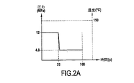
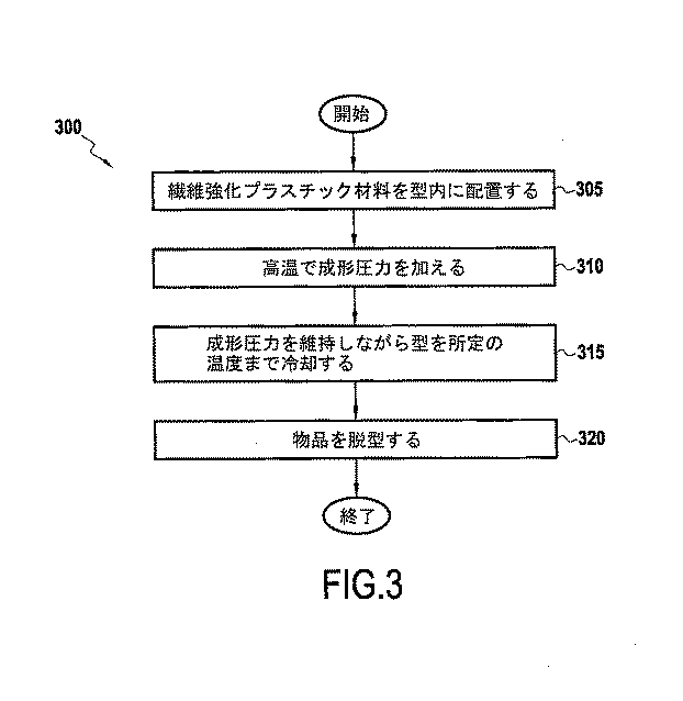
図3は、本開示の実施形態による圧縮成形方法を説明するフローチャートである。図2Bのタイムチャートは、理解をより深めるために図3と併せて見ることができる。 FIG. 3 is a flowchart illustrating a compression molding method according to an embodiment of the present disclosure. The time chart of FIG. 2B can be viewed in conjunction with FIG. 3 for a better understanding.
強化用炭素繊維を所望の長さに切断し、樹脂15と混合することができる。あるいは、使用を容易にするために予め切断された炭素繊維を得ることができる。いくつかの実施形態によれば、適量の樹脂15を保持するために1つ又は複数のキャリヤーフィルムを使用することができ、切断された炭素繊維は、樹脂15の量に関して先に特定した量でキャリヤーフィルム上に存在する樹脂15に適用される。次いで、キャリヤーフィルム、樹脂及び炭素繊維を、炭素繊維をキャリヤーシート上の樹脂に圧縮するように構成された圧縮装置に通過させることができる。その後、1つ以上の後続のキャリヤーシートを、形成されたばかりの炭素繊維強化材料に適用することができる。当業者であれば、繊維強化材料を形成するための他の適切な技術を使用してもよく、例えば、圧縮装置を通過する前に炭素繊維/樹脂材料にキャリヤーシートを適用してもよいことを認識するであろう。代わりに、圧縮装置を使用せず、炭素繊維を樹脂に混合してもよい。
The reinforcing carbon fiber can be cut to a desired length and mixed with the
このように形成された材料は、特定のパネルの製造仕様に従って組み立てられ、圧縮成形ツールに配置されてもよい(ステップ305)。 The material thus formed may be assembled and placed in a compression molding tool according to the manufacturing specifications of the particular panel (step 305).
材料を配置したら、圧縮成形ツールを閉じ、成形圧力を高温で加える(ステップ310)。例えば、圧縮成形中(例えば、圧縮成形の第1の時間)に、成形ツール圧力は2〜15MPaに及ぶことができ、第1の温度(すなわち、圧縮成形ツールが圧縮成形を開始する温度)は、120℃〜160℃、例えば150℃である。 Once the material is in place, the compression molding tool is closed and molding pressure is applied at elevated temperature (step 310). For example, during compression molding (eg, the first time of compression molding), the molding tool pressure can range from 2 to 15 MPa, and the first temperature (ie, the temperature at which the compression molding tool begins compression molding) is , 120°C to 160°C, for example 150°C.
いくつかの実施形態によれば、圧縮成形ツールの圧力は、20秒間の第1の時間にわたって9〜14MPaの第1の圧力で加えられてもよい。第1の時間の後、成形ツール圧力を18〜22MPaの第2の圧力まで増加させ、成形中に70〜100秒間の第2の時間にわたって第2の圧力で保持することができる。例えば、圧縮成形が開始された時点で、図2に示すように、成形ツールの圧力を12MPaに設定し、次に、20秒間で20MPaに増加させることができる。この間、成形ツールの温度を150℃で一定に保つことができる。次いで、温度を150℃に維持しながら成形ツールの圧力を80秒間にわたって20MPaに保持することができる。 According to some embodiments, the compression molding tool pressure may be applied at a first pressure of 9-14 MPa for a first time of 20 seconds. After the first time, the molding tool pressure can be increased to a second pressure of 18-22 MPa and held at the second pressure during molding for a second time of 70-100 seconds. For example, when compression molding is started, the pressure of the molding tool can be set to 12 MPa and then increased to 20 MPa in 20 seconds, as shown in FIG. During this time, the temperature of the molding tool can be kept constant at 150°C. The forming tool pressure can then be maintained at 20 MPa for 80 seconds while maintaining the temperature at 150°C.
第2の成形圧力がシートに対して維持されている間に、圧縮成形ツール及びその中の繊維強化プラスチック物品を、次に、所定の温度に冷却することができる(ステップ315)。例えば、成形ツールは、周囲条件に基づいて約40〜60℃、好ましくは50℃に冷却されてもよい。この冷却時間中、成形ツールの圧力は20MPaに維持されてもよい。当業者であれば、成形ツールの圧力は、時間の経過と共に、例えば100秒間の冷却時間にわたって20MPaから12MPaまで徐々に低下してもよいことを理解するであろう。 The compression molding tool and the fiber reinforced plastic article therein can then be cooled to a predetermined temperature while the second molding pressure is maintained against the sheet (step 315). For example, the molding tool may be cooled to about 40-60°C, preferably 50°C, based on ambient conditions. The pressure of the forming tool may be maintained at 20 MPa during this cooling time. Those skilled in the art will appreciate that the pressure of the molding tool may gradually decrease over time, for example, from 20 MPa to 12 MPa over a cooling time of 100 seconds.
成形ツールが所定の温度(例えば50℃)に達した後、成形された物品を脱型して取り出すことができる(ステップ320)。 After the molding tool reaches a predetermined temperature (eg, 50° C.), the molded article can be demolded and removed (step 320).
圧縮成形に続いて、物品に、任意に仕上げ、例えば塗装及び硬化を施してもよい。 Following compression molding, the article may optionally be finished, eg painted and cured.
本開示の発明を実施することを助けるために、25mmの平均炭素繊維長を用いた以下の非限定的な実施例を提供する。 To assist in practicing the disclosed invention, the following non-limiting examples are provided using an average carbon fiber length of 25 mm.
例1−比較例
炭素繊維強化プラスチック材料の30体積%の割合で存在する炭素繊維を有する、パネルと呼ぶ従来の材料レイアップ。
Example 1-Comparative Example A conventional material layup called a panel with carbon fibers present in a proportion of 30% by volume of carbon fiber reinforced plastic material.
フィラーを含まないビニルエステル樹脂を以下の表に従って調製した。
Palapreg H 2681−01は、ある割合でスチレン、湿潤添加剤、加工添加剤、LDPE、過酸化物及びMgOを含んでいた。 Palaprep H 2681-01 contained a proportion of styrene, wetting additives, processing additives, LDPE, peroxides and MgO.
パネルをビニルエステル樹脂で被覆し、その後、150℃の温度で12MPaで20秒間圧縮成形し、圧力を80秒間で4.8MPaまで減少させた。次いで、型を開け、パネルを脱型し、放冷した。 The panels were coated with vinyl ester resin, then compression molded at 12 MPa for 20 seconds at a temperature of 150° C. and the pressure was reduced to 4.8 MPa for 80 seconds. Then, the mold was opened, the panel was removed from the mold, and it was allowed to cool.
次いで、製造されたパネルを、ミツトヨSV−3000CNCプロフィロメーター装置により測定して、上面の表面粗さを決定した。このプロフィロメーター装置のフィルターカットオフレベルは、2回の別々の測定で2つの異なる値に設定した。カットオフレベルは0.8mm、次いで2.5mmであり、結果を記録した。表2参照。 The manufactured panel was then measured with a Mitutoyo SV-3000 CNC profilometer device to determine the surface roughness of the top surface. The filter cutoff level of this profilometer device was set to two different values in two separate measurements. The cut-off level was 0.8 mm, then 2.5 mm and the results recorded. See Table 2.
参考例 − フィラーを含む樹脂
この参考例では、最初に、比較例1で行ったのと同様に、パネル、すなわち、炭素繊維強化プラスチック材料の30体積%の割合で存在する炭素繊維を有する、パネルと呼ぶ従来の材料レイアップを作製した。
Reference Example- Resin-Containing Resin In this Reference Example , first, as in Comparative Example 1, a panel, that is, a panel having carbon fibers present in a proportion of 30% by volume of the carbon fiber reinforced plastic material. A conventional material layup called
この作製に続いて、比較例と同様に調製されたが、フィラーとして16体積%のCaCO3(CLTE:10×10−6/℃、粒径(D50):3μm)を含むビニル樹脂を調製した。 Following this preparation, a vinyl resin prepared in the same manner as in the comparative example, but containing 16% by volume of CaCO 3 (CLTE: 10×10 −6 /° C., particle diameter (D50): 3 μm) as a filler was prepared. ..
パネルを150℃の温度で12MPaで20秒間圧縮成形し、圧力を80秒間で4.8MPaまで減少させた。次いで、型を開け、パネルを脱型し、放冷した。 The panels were compression molded at a temperature of 150° C. and 12 MPa for 20 seconds and the pressure was reduced to 4.8 MPa in 80 seconds. Then, the mold was opened, the panel was removed from the mold, and it was allowed to cool.
次いで、製造されたパネルを、ミツトヨSV−3000CNCプロフィロメーター装置により測定して、上面の表面粗さを測定した。このプロフィロメーター装置のフィルターカットオフレベルは、2回の別々の測定で2つの異なる値に設定した。カットオフレベルを0.8mm、次いで2.5mmであり、結果を記録した。表2参照。 Next, the manufactured panel was measured with a Mitutoyo SV-3000CNC profilometer device to measure the surface roughness of the upper surface. The filter cutoff level of this profilometer device was set to two different values in two separate measurements. The cut-off level was 0.8 mm, then 2.5 mm and the results recorded. See Table 2.
比較例よりも粗さの値は改善されたが、スチールよりも優れていなかった。 Roughness values were improved over the comparative examples, but not better than steel.
実施例3−低CLTEフィラー長石を含む樹脂
この実施例では、再び、比較例1で行ったのと同様に、パネル、すなわち、炭素繊維強化プラスチック材料の30体積%の割合で存在する炭素繊維を有する、パネルと呼ぶ従来の材料レイアップを作製した。
Example 3-Resin Containing Low CLTE Filler Feldspar In this example, again, as in Comparative Example 1, the panel, i.e. carbon fibers present in a proportion of 30% by volume of the carbon fiber reinforced plastic material, is used. A conventional material layup, called a panel, was made.
この作製に続いて、比較例と同様に調製されたが、16体積%の低CLTEフィラー、この例では長石(CLTE:4.2×10⁻⁶/℃、粒径(D50):3μm)を含むビニル樹脂を調製した。 Following this preparation, a 16% by volume low CLTE filler, feldspar (CLTE: 4.2×10 −6 /° C., particle size (D50): 3 μm) in this example, was prepared as in the comparative example. A vinyl resin containing was prepared.
パネルをビニルエステル樹脂で被覆し、続いて150℃の温度で12MPaで20分間圧縮成形し、圧力を80秒間で4.8MPaまで減少させた。次いで、型を開け、パネルを脱型し、放冷した。 The panels were coated with vinyl ester resin, followed by compression molding at a temperature of 150° C. and 12 MPa for 20 minutes, reducing the pressure to 4.8 MPa in 80 seconds. Then, the mold was opened, the panel was removed from the mold, and it was allowed to cool.
次いで、製造されたパネルを、ミツトヨSV−3000CNCプロフィロメーター装置により測定して、上面の表面粗さを決定した。このプロフィロメーター装置のフィルターカットオフレベルは、2回の別々の測定で2つの異なる値に設定した。カットオフレベルは0.8mm、次いで2.5mmであり、結果を記録した。表2参照。 The manufactured panel was then measured with a Mitutoyo SV-3000 CNC profilometer device to determine the surface roughness of the top surface. The filter cutoff level of this profilometer device was set to two different values in two separate measurements. The cut-off level was 0.8 mm, then 2.5 mm and the results recorded. See Table 2.
粗さ値は比較例よりも改善され、0.8mmのカットオフ値Lcではスチールの粗さ値を満足することができたが、2.5mmのより長いカットオフ値Lcではスチールの粗さ値を満足することができなかった。 The roughness value was improved over the comparative example, and the roughness value of steel could be satisfied with the cutoff value L c of 0.8 mm, but the roughness value of steel was increased with the longer cutoff value L c of 2.5 mm. Could not be satisfied.
実施例4−低CLTEフィラーである溶融シリカを含む樹脂
この実施例では、再び、比較例1で行ったのと同様に、パネル、すなわち、炭素繊維強化プラスチック材料の30体積%の割合で存在する炭素繊維を有する、パネルと呼ぶ従来の材料レイアップを作製した。
Example 4-Resin Containing Fused Silica as Low CLTE Filler In this example, again, as in Comparative Example 1, is present in a proportion of 30% by volume of the panel, i.e. carbon fiber reinforced plastic material. A conventional material layup called a panel with carbon fibers was made.
この作製に続いて、比較例と同様に調製されたが、16体積%の低CLTEフィラー、この例では、線熱膨張係数0.5、粒径4μmの溶融シリカを含むビニル樹脂を調製した。 Following this preparation, a vinyl resin containing 16% by volume of low CLTE filler, in this example, a fused silica having a linear thermal expansion coefficient of 0.5 and a particle size of 4 μm, was prepared as in the comparative example.
パネルをビニルエステル樹脂で被覆し、その後、150℃の温度で12MPaで20秒間圧縮成形し、圧力を80秒間で4.8MPaまで減少させた。次いで、型を開け、パネルを脱型し、放冷した。 The panels were coated with vinyl ester resin, then compression molded at 12 MPa for 20 seconds at a temperature of 150° C. and the pressure was reduced to 4.8 MPa for 80 seconds. Then, the mold was opened, the panel was removed from the mold, and it was allowed to cool.
次いで、作製したパネルをミツトヨSV−3000プロフィロメーター装置により測定して、上面の表面粗さを決定した。このプロフィロメーター装置のフィルターカットオフレベルは、2回の別々の測定で2つの異なる値に設定した。カットオフレベルは0.8mm、次いで2.5mmであり、結果を記録した。表2参照。 Next, the produced panel was measured with a Mitutoyo SV-3000 profilometer device to determine the surface roughness of the upper surface. The filter cutoff level of this profilometer device was set to two different values in two separate measurements. The cut-off level was 0.8 mm, then 2.5 mm and the results recorded. See Table 2.
粗さ値は0.8mm及び2.5mmのカットオフ値Lcの両方について実施例3と同様であった。しかしながら、成形パネルは実質的により軽量であった。 Roughness values were similar to Example 3 for both 0.8 mm and 2.5 mm cutoff values L c . However, the molded panel was substantially lighter.
実施例5−低CLTEフィラーである溶融シリカを含む樹脂−改変成形及び冷却プロセス
この実施例では、再び、比較例1で行ったのと同様に、パネル、すなわち、炭素繊維強化プラスチック材料の30体積%の割合で存在する炭素繊維を有する、パネルと呼ぶ従来の材料レイアップを作製した。
Example 5-Resin Containing Fused Silica as Low CLTE Filler-Modified Molding and Cooling Process In this example, again, as in Comparative Example 1, 30 volumes of panel, i.e. carbon fiber reinforced plastic material, was used. A conventional material layup, called a panel, was made with carbon fibers present in a percentage of.
この作製に続いて、比較例と同様に調製されたが、21体積%の低CLTEフィラー、この例では、溶融シリカを含むビニル樹脂を調製した。 Following this preparation, a vinyl resin was prepared similar to the comparative example, but with 21% by volume of low CLTE filler, in this example fused silica.
パネルをビニルエステル樹脂で被覆し、その後、150℃の温度で12MPaで20秒間圧縮成形し、圧力を80秒間で20MPaまで増加させた。 The panel was coated with vinyl ester resin, then compression molded at 12 MPa for 20 seconds at a temperature of 150° C. and the pressure was increased to 20 MPa for 80 seconds.
次いで、成形ツールを、さらに熱を加えないが、圧力を20MPaに維持したまま周囲条件で放置した。これは、成形ツールの温度が50℃に達するまで行った。型を開け、パネルを脱型し、さらに放冷した。 The molding tool was then left at ambient conditions with no further heat applied, while maintaining the pressure at 20 MPa. This was done until the temperature of the forming tool reached 50°C. The mold was opened, the panel was removed from the mold, and it was allowed to cool.
次いで、作製したパネルをミツトヨSV−3000プロフィロメーター装置により測定して、上面の表面粗さを決定した。このプロフィロメーター装置のフィルターカットオフレベルは、2回の別々の測定で2つの異なる値に設定した。カットオフレベルは0.8mm、次いで2.5mmであり、結果を記録した。表2参照。 Next, the produced panel was measured with a Mitutoyo SV-3000 profilometer device to determine the surface roughness of the upper surface. The filter cutoff level of this profilometer device was set to two different values in two separate measurements. The cut-off level was 0.8 mm, then 2.5 mm and the results recorded. See Table 2.
0.8mm及び2.5mmのカットオフ値Lcの両方の場合のこの例の粗さ値は、スチールの粗さ値に達し、より勝っていることができた。 The roughness values of this example for both 0.8 mm and 2.5 mm cut-off value L c could reach and surpass that of steel.
実施例5’−低CLTEフィラーである溶融シリカ21%を含む樹脂
この実施例では、再び、比較例1で行ったのと同様に、パネル、すなわち、炭素繊維強化プラスチック材料の30体積%の割合で存在する炭素繊維を有する、パネルと呼ぶ従来の材料レイアップを作製した。
Example 5'-Resin containing 21% fused silica, a low CLTE filler In this example, again, as in Comparative Example 1, the panel, i.e. the proportion of 30% by volume of the carbon fiber reinforced plastic material. A conventional material layup called a panel was made with carbon fibers present in.
この作製に続いて、比較例と同様に調製されたが、21体積%の低CLTEフィラー、この例では、溶融シリカを含むビニル樹脂を調製した。 Following this preparation, a vinyl resin was prepared similar to the comparative example, but with 21% by volume of low CLTE filler, in this example fused silica.
パネルをビニルエステル樹脂で被覆し、その後、150℃の温度で12MPaで20秒間圧縮成形し、圧力を80秒間で20MPaまで増加させた。 The panel was coated with vinyl ester resin, then compression molded at 12 MPa for 20 seconds at a temperature of 150° C. and the pressure was increased to 20 MPa for 80 seconds.
次いで、型を開け、パネルを脱型し、さらに放冷した。
表2は、6つの例についての結果と、スチールパネルについての参考情報を示す。
Table 2 shows the results for six examples and reference information for steel panels.
本開示を、特定の実施形態及び実施例を参照して説明してきたが、これらの実施形態及び実施例は、本開示の原理及び適用の単なる例示であることを理解されたい。 Although the present disclosure has been described with reference to particular embodiments and examples, it is to be understood that these embodiments and examples are merely illustrative of the principles and applications of the present disclosure.
特許請求の範囲を含む記載を通じて、「含む(comprising a)」という用語は、特に明記しない限り、「少なくとも1つ(又は1種)を含む(comprising at least one)」と同義であると理解すべきである。さらに、特許請求の範囲を含む明細書に記載された範囲は、特に明記しない限り、その端値(end value(s))を含むものとして理解されるべきである。記載した要素についての特定の値は、当業者に知られている許容される製造又は業界の許容差(tolerances)内にあると理解されるべきであり、「実質的に」及び/又は「およそ」及び/又は「概して」という用語の使用は、かかる許容される許容差内にあることを意味する。 Throughout the description, including the claims, the term "comprising a" is understood to be synonymous with "comprising at least one" unless stated otherwise. Should be. Further, the ranges stated in the claims, including the claims, are to be understood as including their end values(s), unless expressly specified otherwise. Specific values for the listed elements are to be understood as being within acceptable manufacturing or industry tolerances known to those of ordinary skill in the art, "substantially" and/or "approximately." Use of the terms "and/or" generally" means within the accepted tolerances.
国家、国際又はその他の標準機関(例えば、ISOなど)の基準が参照されている場合、かかる参照は、本願の優先日における国内又は国際標準機関によって定義された規格を指すことを意図している。このような規格に対するその後の実質的な変更は、本開示及び/又は請求の範囲及び/又は定義を変更することを意図するものではない。 Where national, international or other standards body (eg, ISO) standards are referenced, such references are intended to refer to standards defined by national or international standards bodies at the priority date of this application. .. Subsequent substantive changes to such standards are not intended to change the present disclosure and/or claims and/or definitions.
本明細書及び実施例は、例示にすぎないと見なされ、本開示の真の範囲は、添付の特許請求の範囲によって示されていることが意図される。
本発明に関連する発明の実施態様の一部を以下に示す。
[態様1]
複数の炭素繊維;及び
少なくとも1種の低線熱膨張係数(CLTE)フィラーを含有するビニルエステル樹脂又は不飽和ポリエステル樹脂、
を含む、繊維強化プラスチック材料。
[態様2]
前記少なくとも1つの低CLTEフィラーが、溶融シリカ及び長石から選択される、態様1に記載の繊維強化プラスチック材料。
[態様3]
前記炭素繊維が、チョップド炭素繊維であり、好ましくはランダムに分散されている、態様1又は2に記載の繊維強化プラスチック材料。
[態様4]
前記フィラーが、前記繊維強化プラスチック材料の10〜40体積%の範囲内で前記樹脂中に存在する、態様1〜3のいずれか一つに記載の繊維強化プラスチック材料。
[態様5]
前記複数の炭素繊維が、前記繊維強化プラスチック材料の15〜60体積%の範囲内で存在する、態様1〜4のいずれか一つに記載の繊維強化プラスチック材料。
[態様6]
前記複数の繊維が、前記樹脂によって含浸されている、態様1〜5のいずれか一つに記載の繊維強化プラスチック材料。
[態様7]
前記複数の炭素繊維が50mm以下、好ましくは25mm以下の最大長さを有する、態様1〜6のいずれか一つに記載の繊維強化プラスチック材料。
[態様8]
前記繊維強化プラスチック材料の少なくとも1つの表面が、0.38μm未満、好ましくは0.20μm未満の表面粗さを有し、表面粗さが、プロフィロメーター、例えばミツトヨSV−3000CNCによって測定される、態様7に記載の繊維強化プラスチック材料。
[態様9]
さらに、仕上げ層を含む、態様1〜8のいずれか一つに記載の繊維強化プラスチック材料。
[態様10]
前記仕上げ層がペイントを含む、態様9に記載の繊維強化プラスチック材料。
[態様11]
前記フィラーの粒子が1〜4μm、好ましくは2〜3μmの平均粒径を有する、態様1〜10のいずれか一つに記載の繊維強化プラスチック材料。
[態様12]
繊維強化プラスチック材料を成形する方法であって、
態様1〜11のいずれか一つに記載の繊維強化プラスチック材料を、前記繊維強化プラスチック材料にツール圧力を加えるように構成された圧縮成形ツールに供給する工程と、
前記圧縮成形ツール内で前記繊維強化プラスチック材料を第1の成形ツール温度で圧縮成形する工程と、
前記繊維強化プラスチック材料に対するツール圧力を維持又は増加しながら、圧縮成形された前記繊維強化プラスチック材料を第2の成形ツール温度まで冷却する工程と、
を含む方法。
[態様13]
前記圧縮成形工程の間、ツール圧力が2〜15MPaに及び、第1の成形ツール温度が130℃〜160℃に及ぶ、態様12に記載の方法。
[態様14]
前記ツール圧力が、20秒間の第1の時間にわたって、9〜14MPa、好ましくは12MPaの第1の圧力に維持される、態様12又は13に記載の方法。
[態様15]
前記ツール圧力が、前記第1の時間の後に前記第2の圧力まで増加され、第2の時間にわたって、好ましくは前記成形ツールが第2の温度に達するまで、前記第2の圧力に維持されることを特徴とする、態様14に記載の方法。
[態様16]
前記第2の成形ツール温度が40〜60℃、好ましくは50℃である、態様12〜15のいずれか一つに記載の方法。
[態様17]
前記冷却工程の間に、前記成形ツールが周囲条件に基づいて冷却される、態様12〜16のいずれか一つに記載の方法。
[態様18]
前記成形ツール温度が前記第2の成形ツール温度に達したときに、前記圧縮成形ツールから前記繊維強化プラスチック材料を除去する工程を含む、態様12〜17のいずれか一つに記載の方法。
[態様19]
前記冷却工程の後に、前記繊維強化プラスチック材料に仕上げ層を適用する工程を含む、態様12〜18のいずれか一つに記載の方法。
[態様20]
前記仕上げ層がペイントを含む、態様19に記載の方法。
[態様21]
さらに、前記仕上げ層を硬化させることを含む、請求項19〜20のいずれか一つに記載の方法。
The specification and examples are considered to be exemplary only, and the true scope of the disclosure is intended to be indicated by the appended claims.
Some of the embodiments of the invention related to the present invention are shown below.
[Aspect 1]
A plurality of carbon fibers; and
Vinyl ester resin or unsaturated polyester resin containing at least one low coefficient of linear thermal expansion (CLTE) filler,
Including fiber reinforced plastic materials.
[Aspect 2]
The fiber-reinforced plastic material of aspect 1, wherein the at least one low CLTE filler is selected from fused silica and feldspar.
[Aspect 3]
3. The fiber-reinforced plastic material according to aspect 1 or 2, wherein the carbon fibers are chopped carbon fibers and are preferably randomly dispersed.
[Mode 4]
The fiber-reinforced plastic material according to any one of aspects 1 to 3, wherein the filler is present in the resin within a range of 10 to 40% by volume of the fiber-reinforced plastic material.
[Aspect 5]
The fiber-reinforced plastic material according to any one of aspects 1 to 4, wherein the plurality of carbon fibers are present in the range of 15 to 60% by volume of the fiber-reinforced plastic material.
[Aspect 6]
The fiber-reinforced plastic material according to any one of aspects 1 to 5, wherein the plurality of fibers are impregnated with the resin.
[Aspect 7]
The fiber-reinforced plastic material according to any one of aspects 1 to 6, wherein the plurality of carbon fibers have a maximum length of 50 mm or less, preferably 25 mm or less.
[Aspect 8]
At least one surface of the fiber-reinforced plastic material has a surface roughness of less than 0.38 μm, preferably less than 0.20 μm, the surface roughness being measured by a profilometer, eg Mitutoyo SV-3000CNC, A fiber-reinforced plastic material according to aspect 7.
[Aspect 9]
Furthermore, the fiber reinforced plastic material in any one of the aspects 1-8 containing a finishing layer.
[Aspect 10]
A fiber reinforced plastic material according to aspect 9, wherein the finishing layer comprises paint.
[Aspect 11]
The fiber-reinforced plastic material according to any one of aspects 1 to 10, wherein the particles of the filler have an average particle diameter of 1 to 4 µm, preferably 2 to 3 µm.
[Aspect 12]
A method for molding a fiber reinforced plastic material, comprising:
Supplying the fiber reinforced plastic material according to any one of aspects 1 to 11 to a compression molding tool configured to apply tool pressure to the fiber reinforced plastic material;
Compression molding the fiber reinforced plastic material in the compression molding tool at a first molding tool temperature;
Cooling the compression molded fiber reinforced plastic material to a second molding tool temperature while maintaining or increasing the tool pressure on the fiber reinforced plastic material;
Including the method.
[Aspect 13]
A method according to
[Aspect 14]
A method according to
[Aspect 15]
The tool pressure is increased to the second pressure after the first time and maintained at the second pressure for a second time, preferably until the forming tool reaches a second temperature. 15. The method according to aspect 14, characterized in that
[Aspect 16]
The method according to any one of
[Aspect 17]
17. A method according to any one of aspects 12-16, wherein during the cooling step, the forming tool is cooled based on ambient conditions.
[Aspect 18]
18. A method according to any one of aspects 12-17, comprising removing the fiber reinforced plastic material from the compression molding tool when the molding tool temperature reaches the second molding tool temperature.
[Aspect 19]
19. A method according to any one of aspects 12-18, comprising the step of applying a finishing layer to the fiber reinforced plastic material after the cooling step.
[Aspect 20]
20. The method of aspect 19, wherein the finishing layer comprises paint.
[Aspect 21]
21. The method of any one of claims 19-20, further comprising curing the finish layer.
Claims (24)
0.5〜4.5×10⁻⁶/℃の範囲内の線熱膨張係数を有する少なくとも1種の低線熱膨張係数(CLTE)フィラーを含有するビニルエステル樹脂又は不飽和ポリエステル樹脂、
を含む、繊維強化プラスチック材料であって、
前記複数の炭素繊維が50mm以下の最大長さを有し、
前記繊維強化プラスチック材料の少なくとも1つの表面が、2.5mmのフィルターカットオフ値でプロフィロメーターミツトヨSV−3000CNCによって測定した場合に0.38μm未満の表面粗さRaを有する、
繊維強化プラスチック材料。 A plurality of carbon fibers; and a vinyl ester resin containing at least one low coefficient of linear thermal expansion (CLTE) filler having a coefficient of linear thermal expansion in the range of 0.5 to 4.5×10 −6 /° C. Saturated polyester resin,
A fiber reinforced plastic material, including:
The plurality of carbon fibers have a maximum length of 50 mm or less,
At least one surface of the fiber reinforced plastic material has a surface roughness Ra of less than 0.38 μm as measured by a profilometer Mitutoyo SV-3000 CNC with a filter cutoff value of 2.5 mm.
Fiber reinforced plastic material.
複数の炭素繊維と、0.5〜4.5×10⁻⁶/℃の範囲内の線熱膨張係数を有する少なくとも1種の低線熱膨張係数(CLTE)フィラーを含有するビニルエステル樹脂又は不飽和ポリエステル樹脂とを含む繊維強化プラスチック材料を、前記繊維強化プラスチック材料にツール圧力を加えるように構成された圧縮成形ツールに供給する工程と、
前記圧縮成形ツール内で前記繊維強化プラスチック材料を第1の成形ツール温度で圧縮成形する工程と、
前記繊維強化プラスチック材料に対するツール圧力を維持又は増加しながら、圧縮成形された前記繊維強化プラスチック材料を第2の成形ツール温度まで冷却する工程と、
を含む方法。 A method for molding a fiber reinforced plastic material, comprising:
A vinyl ester resin containing a plurality of carbon fibers and at least one low linear thermal expansion coefficient (CLTE) filler having a linear thermal expansion coefficient in the range of 0.5 to 4.5×10 −6 /° C. Supplying a fiber reinforced plastic material comprising a saturated polyester resin to a compression molding tool configured to apply tool pressure to the fiber reinforced plastic material;
Compression molding the fiber reinforced plastic material in the compression molding tool at a first molding tool temperature;
Cooling the compression molded fiber reinforced plastic material to a second molding tool temperature while maintaining or increasing the tool pressure on the fiber reinforced plastic material;
Including the method.
Applications Claiming Priority (1)
| Application Number | Priority Date | Filing Date | Title |
|---|---|---|---|
| PCT/EP2016/050093 WO2017118476A1 (en) | 2016-01-05 | 2016-01-05 | Carbon fiber reinforced plastic material having high smoothness |
Publications (2)
| Publication Number | Publication Date |
|---|---|
| JP2019506484A JP2019506484A (en) | 2019-03-07 |
| JP6703117B2 true JP6703117B2 (en) | 2020-06-03 |
Family
ID=55229647
Family Applications (1)
| Application Number | Title | Priority Date | Filing Date |
|---|---|---|---|
| JP2018535147A Active JP6703117B2 (en) | 2016-01-05 | 2016-01-05 | Carbon fiber reinforced plastic material with high smoothness |
Country Status (5)
| Country | Link |
|---|---|
| US (1) | US10961361B2 (en) |
| EP (1) | EP3400257B1 (en) |
| JP (1) | JP6703117B2 (en) |
| CN (1) | CN108291034A (en) |
| WO (1) | WO2017118476A1 (en) |
Families Citing this family (1)
| Publication number | Priority date | Publication date | Assignee | Title |
|---|---|---|---|---|
| US12522702B2 (en) * | 2020-04-28 | 2026-01-13 | Japan Composite Co., Ltd. | Thin plate molding material and molded article |
Family Cites Families (17)
| Publication number | Priority date | Publication date | Assignee | Title |
|---|---|---|---|---|
| JPS61213225A (en) * | 1985-03-18 | 1986-09-22 | Adachi Shin Sangyo Kk | Thermosetting resin molding material |
| JPH0739146B2 (en) * | 1988-02-26 | 1995-05-01 | 安達新産業株式会社 | Resin molding material |
| JP3032582B2 (en) | 1990-12-26 | 2000-04-17 | 三菱化学株式会社 | Method for improving appearance of fiber-reinforced thermoplastic resin molded product |
| US5604266A (en) * | 1992-10-15 | 1997-02-18 | Ecomat, Inc. | Cured unsaturated polyest-polyurethane highly filled resin materials and process for preparing them |
| NL1012103C2 (en) * | 1999-05-19 | 2000-11-21 | Dsm Nv | Sheet-shaped product of a thermosetting resin mixture and carbon fibers. |
| JP2001139831A (en) * | 1999-11-15 | 2001-05-22 | Toray Ind Inc | Carbon fiber bulk molding compound material and molded product |
| JP3844283B2 (en) * | 2001-08-07 | 2006-11-08 | 東海興業株式会社 | Composite resin products |
| JP2007131697A (en) | 2005-11-09 | 2007-05-31 | Toho Tenax Co Ltd | Fiber-reinforced thermoplastic resin stampable sheet and fiber-reinforced thermoplastic resin molded product |
| US20070173584A1 (en) * | 2006-01-23 | 2007-07-26 | Ashland Licensing And Intellectual Property Llc | Composite polymers |
| JP4955294B2 (en) * | 2006-04-04 | 2012-06-20 | 本田技研工業株式会社 | Carbon fiber reinforced plastic molding material for automobile parts and carbon fiber reinforced plastic molding for automobile parts |
| US20070235698A1 (en) * | 2006-04-05 | 2007-10-11 | General Electric Company | vehicular body part |
| JP5232496B2 (en) * | 2008-02-21 | 2013-07-10 | ジャパンコンポジット株式会社 | Unsaturated polyester resin composition, molding material containing the same, and molded article |
| JP2011056798A (en) * | 2009-09-10 | 2011-03-24 | Mitsubishi Rayon Co Ltd | Method for manufacturing fiber-reinforced composite material molded product |
| CN102632622B (en) * | 2012-05-03 | 2015-01-07 | 湖南欧亚碳纤维复合材料有限公司 | Preparation method of carbon fiber table leg produced by fiber-reinforced resin-matrix composite furniture material |
| CN103059532B (en) * | 2012-12-29 | 2015-06-03 | 昆明普尔顿环保科技股份有限公司 | A plastic tube processed from bulk molding compound |
| CN104419206A (en) * | 2013-08-24 | 2015-03-18 | 黑龙江鑫达企业集团有限公司 | Preparation method of high-performance fiber reinforced polyphenylene sulfide composite material |
| EP3092122B8 (en) * | 2014-01-09 | 2022-06-15 | Toyota Motor Europe | Reinforced plastic material having high smoothness |
-
2016
- 2016-01-05 JP JP2018535147A patent/JP6703117B2/en active Active
- 2016-01-05 US US15/779,588 patent/US10961361B2/en active Active
- 2016-01-05 CN CN201680069315.9A patent/CN108291034A/en active Pending
- 2016-01-05 WO PCT/EP2016/050093 patent/WO2017118476A1/en not_active Ceased
- 2016-01-05 EP EP16701419.0A patent/EP3400257B1/en not_active Not-in-force
Also Published As
| Publication number | Publication date |
|---|---|
| US10961361B2 (en) | 2021-03-30 |
| CN108291034A (en) | 2018-07-17 |
| EP3400257A1 (en) | 2018-11-14 |
| WO2017118476A1 (en) | 2017-07-13 |
| JP2019506484A (en) | 2019-03-07 |
| EP3400257B1 (en) | 2020-10-21 |
| US20200299470A1 (en) | 2020-09-24 |
Similar Documents
| Publication | Publication Date | Title |
|---|---|---|
| JP7208390B2 (en) | High-strength composite with low heat release | |
| EP3092122B1 (en) | Reinforced plastic material having high smoothness | |
| CN110831746A (en) | Pultruded impregnated fibers and uses thereof | |
| CN106626662A (en) | Sandwich-structure composite material and preparation method thereof | |
| WO2019031111A1 (en) | Prepreg laminate, method for manufacturing fiber-reinforced plastic using prepreg laminate, and fiber-reinforced plastic | |
| WO2019189384A1 (en) | Method for manufacturing molded article | |
| JP6703117B2 (en) | Carbon fiber reinforced plastic material with high smoothness | |
| EP0296611B1 (en) | Stamping-moldable material | |
| KR100249575B1 (en) | Method for producing a composite product by molding | |
| US12515417B2 (en) | Hybrid fiber based molding thermoplastic article and process of forming same | |
| EP3524413B1 (en) | Resin-based composite structure and method for forming the same | |
| Beng et al. | Effect of ply lay-up and curing pressure on void content in GFRP laminates of unsaturated polyester resin-reinforced woven E-glass fibers | |
| JP2579568B2 (en) | Method for producing glass fiber reinforced sheet | |
| US20130153121A1 (en) | Methods, apparatus and systems for reducing warpage in polymers with continuous fibers | |
| EP3442795B1 (en) | Vehicle components formed with epoxidized chopped glass bonded to a thermoset matrix | |
| JP2006001021A (en) | Appearance part and its manufacturing method | |
| JP2747869B2 (en) | Method for producing glass fiber reinforced sheet | |
| KR102174303B1 (en) | Low specific gravity sheet molding compound composite sheet | |
| WO2024203468A1 (en) | Resin molded body and method for manufacturing same | |
| JPH0516225A (en) | Polypropylene film for processing | |
| HK1008431B (en) | Stamping-moldable material |
Legal Events
| Date | Code | Title | Description |
|---|---|---|---|
| A621 | Written request for application examination |
Free format text: JAPANESE INTERMEDIATE CODE: A621 Effective date: 20180705 |
|
| A131 | Notification of reasons for refusal |
Free format text: JAPANESE INTERMEDIATE CODE: A131 Effective date: 20190702 |
|
| A977 | Report on retrieval |
Free format text: JAPANESE INTERMEDIATE CODE: A971007 Effective date: 20190628 |
|
| A521 | Request for written amendment filed |
Free format text: JAPANESE INTERMEDIATE CODE: A523 Effective date: 20191002 |
|
| A131 | Notification of reasons for refusal |
Free format text: JAPANESE INTERMEDIATE CODE: A131 Effective date: 20200225 |
|
| A521 | Request for written amendment filed |
Free format text: JAPANESE INTERMEDIATE CODE: A523 Effective date: 20200330 |
|
| TRDD | Decision of grant or rejection written | ||
| A01 | Written decision to grant a patent or to grant a registration (utility model) |
Free format text: JAPANESE INTERMEDIATE CODE: A01 Effective date: 20200407 |
|
| A61 | First payment of annual fees (during grant procedure) |
Free format text: JAPANESE INTERMEDIATE CODE: A61 Effective date: 20200507 |
|
| R150 | Certificate of patent or registration of utility model |
Ref document number: 6703117 Country of ref document: JP Free format text: JAPANESE INTERMEDIATE CODE: R150 |
|
| S111 | Request for change of ownership or part of ownership |
Free format text: JAPANESE INTERMEDIATE CODE: R313113 |
|
| R350 | Written notification of registration of transfer |
Free format text: JAPANESE INTERMEDIATE CODE: R350 |
|
| R250 | Receipt of annual fees |
Free format text: JAPANESE INTERMEDIATE CODE: R250 |