JP6800901B2 - Object area identification device, object area identification method and program - Google Patents
Object area identification device, object area identification method and program Download PDFInfo
- Publication number
- JP6800901B2 JP6800901B2 JP2018039979A JP2018039979A JP6800901B2 JP 6800901 B2 JP6800901 B2 JP 6800901B2 JP 2018039979 A JP2018039979 A JP 2018039979A JP 2018039979 A JP2018039979 A JP 2018039979A JP 6800901 B2 JP6800901 B2 JP 6800901B2
- Authority
- JP
- Japan
- Prior art keywords
- cost
- pixel
- image
- transition
- area identification
- Prior art date
- Legal status (The legal status is an assumption and is not a legal conclusion. Google has not performed a legal analysis and makes no representation as to the accuracy of the status listed.)
- Active
Links
Images










Classifications
-
- G—PHYSICS
- G06—COMPUTING OR CALCULATING; COUNTING
- G06V—IMAGE OR VIDEO RECOGNITION OR UNDERSTANDING
- G06V10/00—Arrangements for image or video recognition or understanding
- G06V10/70—Arrangements for image or video recognition or understanding using pattern recognition or machine learning
- G06V10/82—Arrangements for image or video recognition or understanding using pattern recognition or machine learning using neural networks
-
- G—PHYSICS
- G06—COMPUTING OR CALCULATING; COUNTING
- G06F—ELECTRIC DIGITAL DATA PROCESSING
- G06F18/00—Pattern recognition
- G06F18/20—Analysing
- G06F18/21—Design or setup of recognition systems or techniques; Extraction of features in feature space; Blind source separation
- G06F18/214—Generating training patterns; Bootstrap methods, e.g. bagging or boosting
-
- G—PHYSICS
- G06—COMPUTING OR CALCULATING; COUNTING
- G06F—ELECTRIC DIGITAL DATA PROCESSING
- G06F18/00—Pattern recognition
- G06F18/20—Analysing
- G06F18/24—Classification techniques
- G06F18/241—Classification techniques relating to the classification model, e.g. parametric or non-parametric approaches
-
- G—PHYSICS
- G06—COMPUTING OR CALCULATING; COUNTING
- G06V—IMAGE OR VIDEO RECOGNITION OR UNDERSTANDING
- G06V10/00—Arrangements for image or video recognition or understanding
- G06V10/40—Extraction of image or video features
- G06V10/44—Local feature extraction by analysis of parts of the pattern, e.g. by detecting edges, contours, loops, corners, strokes or intersections; Connectivity analysis, e.g. of connected components
- G06V10/443—Local feature extraction by analysis of parts of the pattern, e.g. by detecting edges, contours, loops, corners, strokes or intersections; Connectivity analysis, e.g. of connected components by matching or filtering
- G06V10/449—Biologically inspired filters, e.g. difference of Gaussians [DoG] or Gabor filters
- G06V10/451—Biologically inspired filters, e.g. difference of Gaussians [DoG] or Gabor filters with interaction between the filter responses, e.g. cortical complex cells
- G06V10/454—Integrating the filters into a hierarchical structure, e.g. convolutional neural networks [CNN]
-
- G—PHYSICS
- G06—COMPUTING OR CALCULATING; COUNTING
- G06V—IMAGE OR VIDEO RECOGNITION OR UNDERSTANDING
- G06V20/00—Scenes; Scene-specific elements
- G06V20/40—Scenes; Scene-specific elements in video content
- G06V20/41—Higher-level, semantic clustering, classification or understanding of video scenes, e.g. detection, labelling or Markovian modelling of sport events or news items
-
- G—PHYSICS
- G06—COMPUTING OR CALCULATING; COUNTING
- G06V—IMAGE OR VIDEO RECOGNITION OR UNDERSTANDING
- G06V20/00—Scenes; Scene-specific elements
- G06V20/50—Context or environment of the image
- G06V20/56—Context or environment of the image exterior to a vehicle by using sensors mounted on the vehicle
Landscapes
- Engineering & Computer Science (AREA)
- Theoretical Computer Science (AREA)
- Evolutionary Computation (AREA)
- General Physics & Mathematics (AREA)
- Physics & Mathematics (AREA)
- Artificial Intelligence (AREA)
- Computer Vision & Pattern Recognition (AREA)
- Multimedia (AREA)
- Data Mining & Analysis (AREA)
- General Health & Medical Sciences (AREA)
- Life Sciences & Earth Sciences (AREA)
- Health & Medical Sciences (AREA)
- Software Systems (AREA)
- Databases & Information Systems (AREA)
- Medical Informatics (AREA)
- Biodiversity & Conservation Biology (AREA)
- Biomedical Technology (AREA)
- Molecular Biology (AREA)
- Computing Systems (AREA)
- Bioinformatics & Cheminformatics (AREA)
- Bioinformatics & Computational Biology (AREA)
- Evolutionary Biology (AREA)
- General Engineering & Computer Science (AREA)
- Computational Linguistics (AREA)
- Image Analysis (AREA)
- Traffic Control Systems (AREA)
Description
本発明の実施形態は、物体領域識別装置、物体領域識別方法およびプログラムに関する。 Embodiments of the present invention relate to an object area identification device, an object area identification method and a program.
画像の画素毎に物体種別をラベリングすることは、セマンティックセグメンテーションと呼ばれ、幅広い応用がある。例えば、自動車の自動運転では、車載カメラの映像から自動車、道路、歩行者などの領域を識別することで自動車の走路を決定できる。また、監視カメラの映像から人物の領域を識別することで、不審者の検出や人数カウント等に利用できる。セマンティックセグメンテーションによるラベリングが高精度なほど、その後の処理の信頼性も上がる。 Labeling the object type for each pixel of an image is called semantic segmentation and has a wide range of applications. For example, in automatic driving of an automobile, the track of the automobile can be determined by identifying areas such as an automobile, a road, and a pedestrian from an image of an in-vehicle camera. In addition, by identifying the area of a person from the image of the surveillance camera, it can be used for detecting a suspicious person, counting the number of people, and the like. The more accurate the labeling by semantic segmentation, the more reliable the subsequent processing.
セマンティックセグメンテーションの手法としては、画素毎に独立して物体ラベルを求める方法が広く知られている。しかし、物体ラベルは画素毎に大きく変化しないため、画像の大域的な情報を用いることで、ラベリング精度の向上が期待できる。そこで、大域的な情報を用いて画素毎の物体ラベルを決定する方法も提案されている。しかし、大域的な情報を用いて画素毎の物体ラベルを決定する従来の方法は、各画素の物体ラベルを周辺画素との関係から試行錯誤的に求めるものであるため、高精度のラベリングを行うためには計算を繰り返し行う必要がある。このため、特に解像度の高い画像に対しては計算時間が長くかかってしまうという問題があり、大域的な情報を用いた高精度なラベリングをより少ない計算量で実現できるようにすることが求められている。 As a method of semantic segmentation, a method of obtaining an object label independently for each pixel is widely known. However, since the object label does not change significantly for each pixel, it can be expected that the labeling accuracy will be improved by using the global information of the image. Therefore, a method of determining the object label for each pixel using global information has also been proposed. However, the conventional method of determining the object label for each pixel using global information is to obtain the object label of each pixel by trial and error from the relationship with the peripheral pixels, and therefore perform high-precision labeling. In order to do so, it is necessary to repeat the calculation. For this reason, there is a problem that the calculation time is long, especially for high-resolution images, and it is required to realize high-precision labeling using global information with a smaller amount of calculation. ing.
本発明が解決しようとする課題は、大域的な情報を用いた高精度なラベリングをより少ない計算量で実現できる物体領域識別装置、物体領域識別方法およびプログラムを提供することである。 An object to be solved by the present invention is to provide an object area identification device, an object area identification method, and a program capable of realizing highly accurate labeling using global information with a smaller amount of calculation.
実施形態の物体領域識別装置は、画像の各画素が予め定めた複数の物体クラスのいずれに属するかを識別して画素毎に物体種別のラベリングを行う物体領域識別装置であって、ベースコスト算出部と、遷移コスト推定部と、累積コスト算出部と、クラス決定部と、を備える。ベースコスト算出部は、前記各画素において前記複数の物体クラス毎のベースコストを算出する。遷移コスト推定部は、前記画像上の隣接する画素間で物体クラスが遷移する際に要する遷移コストを推定する。累積コスト算出部は、前記画像上に設定した走査方向に沿って、前記ベースコストと前記遷移コストを前記複数の物体クラス毎に累積して、前記各画素における前記複数の物体クラス毎の累積コストを算出する。クラス決定部は、前記累積コストに基づいて、前記各画素の物体クラスを決定する。 The object area identification device of the embodiment is an object area identification device that identifies which of a plurality of predetermined object classes each pixel of an image belongs to and labels the object type for each pixel, and calculates the base cost. It includes a unit, a transition cost estimation unit, a cumulative cost calculation unit, and a class determination unit. The base cost calculation unit calculates the base cost for each of the plurality of object classes in each pixel. The transition cost estimation unit estimates the transition cost required when the object class transitions between adjacent pixels on the image. The cumulative cost calculation unit accumulates the base cost and the transition cost for each of the plurality of object classes along the scanning direction set on the image, and the cumulative cost for each of the plurality of object classes in each pixel. Is calculated. The class determination unit determines the object class of each pixel based on the cumulative cost.
以下、添付図面を参照しながら、実施形態の物体領域識別装置、物体領域識別方法およびプログラムについて詳細に説明する。本実施形態は、画像の各画素が予め定めた複数の物体クラスのいずれに属するかを識別して画素毎に物体種別のラベリングを行うものであり、特に、大域的な情報を用いた高精度なラベリングをより少ない計算量で実現する、新規なセマンティックセグメンテーションの手法を提案するものである。 Hereinafter, the object area identification device, the object area identification method, and the program of the embodiment will be described in detail with reference to the accompanying drawings. In the present embodiment, each pixel of an image is identified to which of a plurality of predetermined object classes, and the object type is labeled for each pixel. In particular, high accuracy using global information is used. It proposes a new semantic segmentation method that realizes simple labeling with a smaller amount of calculation.
大域的な情報を用いたセマンティックセグメンテーションのエネルギー関数は、下記式(1)のように表すことができる。

上記式(1)の右辺第2項のペナルティp(ペアワイズ項と呼ばれることもある)が0の場合、右辺第1項のコストUが最小となる物体クラスcが画素位置x毎に決定される。これは、画素毎に独立して物体ラベルを求めるセマンティックセグメンテーションの手法(例えば、非特許文献1に開示される手法)と同様である。上記式(1)では、右辺第1項のコストUに対して、右辺第2項のペナルティpが加算されることで、画素毎の急激なラベルの変化が抑制される。 When the penalty p (sometimes called a pairwise term) of the second term on the right side of the above equation (1) is 0, the object class c that minimizes the cost U of the first term on the right side is determined for each pixel position x. .. This is the same as the method of semantic segmentation in which the object label is independently obtained for each pixel (for example, the method disclosed in Non-Patent Document 1). In the above equation (1), a sudden change in the label for each pixel is suppressed by adding the penalty p of the second term on the right side to the cost U of the first term on the right side.
大域的な情報を用いたセマンティックセグメンテーションの従来手法(例えば、特許文献1に開示される手法や非特許文献2に開示される手法)では、上記式(1)を解いて高精度なラベリングを行うためには、cx(画素位置xにおける物体クラスc)を更新しながら安定するまで繰り返し計算を行う必要があり、計算時間が長くなる。これに対し本実施形態では、後述の「累積コスト」の概念を導入し、動的計画法を用いて上記式(1)を近似的に解くことで、1回の操作で画像の各画素の物体クラスを決定する。これにより、繰り返しの計算を行う従来手法と比較して計算時間を大幅に短縮することができる。
In the conventional method of semantic segmentation using global information (for example, the method disclosed in
図1は、本実施形態に係る物体領域識別装置10の機能的な構成例を示すブロック図である。この物体領域識別装置10は、図1に示すように、ベースコスト算出部11と、遷移コスト推定部12と、累積コスト算出部13と、クラス決定部14と、を備える。
FIG. 1 is a block diagram showing a functional configuration example of the object
ベースコスト算出部11は、処理対象となる画像を入力とし、この画像の各画素において複数の物体クラス毎のベースコストを算出する。ここで、複数の物体クラスは、用途に応じて予め定められる。上述の自動運転向けの用途では、一例として、「自動車」、「道路」、「歩行者」、「その他」の4つの物体クラスが予め定められる。以下では、この事例を適宜想定して説明するが、この例に限定されるものではない。
The base
ベースコスト算出部11により算出されるベースコストは、上記式(1)のコストUに相当する。ベースコスト算出部11は、例えば、非特許文献1に開示されるニューラルネットワーク(SegNet)などを利用して実現できる。ただし、非特許文献1のニューラルネットワークは、物体クラス毎に計算した値が最大値を取る物体クラスをその画素の物体クラスとして決定するため、非特許文献1のニューラルネットワークにより計算される値sを、下記式(2)により、ベースコストUに変換する。
ここでは、非特許文献1のニューラルネットワークで計算される値sがシグモイド関数などを施すことで0〜1に正規化されていることを想定し、上記式(2)によりベースコストUに変換している。ただし、ベースコスト算出部11は、真の物体クラスで値が小さくなるようなベースコストUを算出できればよく、その実現方法は上述の例に限らない。なお、非特許文献1のニューラルネットワークは、事前に大量の画像を使って学習(ネットワークパラメータが更新)されるが、その学習方法については説明を省略する。
Here, assuming that the value s calculated by the neural network of
遷移コスト推定部12は、画像上の隣接する画素間で物体クラスが遷移する際に要する遷移コストを推定する。遷移コストは、同一の物体クラスでは0、異なる物体クラス間では非負となるようにし、遷移が容易な物体クラスほど0に近い値を持つようにする。遷移コスト推定部12により推定される遷移コストは、上記式(1)のペナルティpに相当する。
The transition
遷移コストの概要を図2を使って説明する。ここでは、自動車の自動運転向けの用途を想定し、物体クラスとして、「自動車」、「道路」、「歩行者」、「その他」の4つの物体クラスが予め定められているものとする。図2に示す画像例は、自動車110が道路120上を走行している様子を撮影した画像100であり、自動車110に属する画素101と道路120に属する画素102とが図2に示す位置で隣接している。なお、図2では説明のため、画素101と画素102を実際の画素の大きさよりも大きく描いている。
The outline of the transition cost will be described with reference to FIG. Here, assuming an application for automatic driving of an automobile, it is assumed that four object classes of "automobile", "road", "pedestrian", and "other" are predetermined as object classes. The image example shown in FIG. 2 is an
図2に示す画像100において、画素101と画素102の位置では、画素101から画素102への方向で真の物体クラスが「自動車」から「道路」に変化している。よって、画素101から画素102への方向では、物体クラスが「自動車」から「道路」に遷移する遷移コストは0に近くなり、その他の物体クラスの遷移、例えば「自動車」→「歩行者」や、「その他」→「自動車」などの遷移コストは大きな値が推定されることが望ましい。また、図2の画像100では、画素103と画素104がともに道路120に属するため、これら画素103と画素104の位置では、物体クラスが「道路」から他の物体クラスに遷移する遷移コストをはじめ、あらゆる物体クラスの遷移に対する遷移コストは大きな値が推定されることで、画素103と画素104の間で物体クラスが変わってしまうのを防ぐ。
In the
遷移コスト推定部12は、処理対象となる画像の位置と方向に応じて上述の遷移コストを推定する。この遷移コスト推定部12は、処理対象となる画像の各画素における後述の累積コストが真の物体クラスで最小となるような遷移コストを推定するように、学習用データを用いて事前に学習される。遷移コスト推定部12は、例えば、ニューラルネットワークとして構築することができる。この場合、事前の学習によりニューラルネットワークのパラメータ(各層の重みやバイアス)が更新される。なお、遷移コスト推定部12の具体的な学習方法については、詳細を後述する。
The transition
累積コスト算出部13は、処理対象となる画像上に設定した走査方向に沿って、上述のベースコストと遷移コストを複数の物体クラス毎に累積して、処理対象となる画像の各画素における複数の物体クラス毎の累積コストを算出する。クラス決定部14は、累積コスト算出部13により算出された累積コストに基づいて、処理対象となる画像の各画素の物体クラスを決定する。
The cumulative
本実施形態に係る物体領域識別装置10は、上述のように、動的計画法を用いて上記式(1)を近似的に解くことで、処理対象となる画像の各画素の物体クラスを決定する。つまり、累積コスト算出部13による累積コストの算出およびクラス決定部14による物体クラスの決定が、動的計画法を用いて行われる。
As described above, the object
動的計画法を用いた累積コストの算出および物体クラスの決定の概要は、以下の通りである。すなわち、画像上の任意の画素位置Aに対し、画像上に設定した走査方向に対して1つ戻った画素位置を画素位置Bとする。このとき、画素位置Aの物体クラス毎のベースコストに、画素位置Bにおける遷移コストと累積コストの最小の組み合わせを加算したものを、画素位置Aの累積コストとして算出する。この操作を、画素位置Aを走査方向に沿って1画素ずつずらしながら行って、画像の全画素について物体クラス毎の累積コストを算出する。画像に複数の走査方向を設定した場合は、上述の操作を走査方向毎に行い、走査方向毎に算出した累積コストを物体カテゴリ毎に加算して統合累積コストとする。そして、画像の各画素において、累積コスト(走査方向が複数の場合は統合累積コスト)が最も小さい値をとる物体クラスを、その画素の物体クラスとして決定する。 The outline of the calculation of cumulative cost and the determination of object class using dynamic programming is as follows. That is, the pixel position B is defined as the pixel position that is one step back from the arbitrary pixel position A on the image with respect to the scanning direction set on the image. At this time, the cumulative cost of the pixel position A is calculated by adding the minimum combination of the transition cost and the cumulative cost at the pixel position B to the base cost of each object class of the pixel position A. This operation is performed while shifting the pixel position A one pixel at a time along the scanning direction to calculate the cumulative cost for each object class for all the pixels of the image. When a plurality of scanning directions are set for the image, the above operation is performed for each scanning direction, and the cumulative cost calculated for each scanning direction is added for each object category to obtain the integrated cumulative cost. Then, for each pixel of the image, the object class having the smallest cumulative cost (integrated cumulative cost when there are a plurality of scanning directions) is determined as the object class of the pixel.
動的計画法を用いた画像処理の技術としては、非特許文献3に開示される技術が知られている。上述の動的計画法を用いた累積コストの算出および物体クラスの決定は、例えば、この非特許文献3に開示される技術を応用することで実現できる。ただし、非特許文献3に開示される技術はステレオ画像を利用した視差画像の生成に関するものであり、これをそのまま適用することはできない。このため、新たに定式化を行う。以下では、非特許文献3に開示される技術を応用した累積コストの算出および物体クラスの決定の具体例について詳しく説明する。 As a technique of image processing using a dynamic programming method, a technique disclosed in Non-Patent Document 3 is known. The calculation of the cumulative cost and the determination of the object class using the above-mentioned dynamic programming can be realized, for example, by applying the technique disclosed in Non-Patent Document 3. However, the technique disclosed in Non-Patent Document 3 relates to the generation of a parallax image using a stereo image, and this cannot be applied as it is. Therefore, a new formulation is performed. In the following, specific examples of calculating the cumulative cost and determining the object class by applying the technique disclosed in Non-Patent Document 3 will be described in detail.
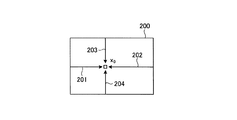
まず、処理対象となる画像上に走査方向を設定する。走査方向は複数設定することができる。走査方向の数が多いほど、セマンティックセグメンテーションのラベリング精度の向上が期待できる反面、計算量が多くなる。このため、用途に応じて要求される精度と装置の演算処理能力とに応じて、最適な数の走査方向を設定することが望ましい。図3−1は、画像200上に4つの走査方向を設定した例を示しており、画素位置x0に向かって、水平に左から右への走査方向201と、水平に右から左への走査方向202と、垂直に上から下への走査方向203と、垂直に下から上への走査方向204とが設定されている。また、図3−2は、画像200上に8つの走査方向を設定した例を示しており、図3−1で示した4つの走査方向に加えて、画素位置x0に向かって、左下から右上へ45度の走査方向205と、右上から左下へ45度の走査方向206と、左上から右下へ45度の走査方向207と、右下から左上へ45度の走査方向208とが設定されている。
First, the scanning direction is set on the image to be processed. A plurality of scanning directions can be set. As the number of scanning directions increases, the labeling accuracy of semantic segmentation can be expected to improve, but the amount of calculation increases. Therefore, it is desirable to set the optimum number of scanning directions according to the accuracy required for the application and the arithmetic processing capacity of the apparatus. FIG. 3-1 shows an example in which four scanning directions are set on the
次に、処理対象となる画像上に設定した走査方向毎に、画像の各画素における累積コストを算出する。走査方向毎に行う処理は同一であるため、以下では1つの走査方向に着目して説明する。 Next, the cumulative cost for each pixel of the image is calculated for each scanning direction set on the image to be processed. Since the processing performed for each scanning direction is the same, the following description will focus on one scanning direction.
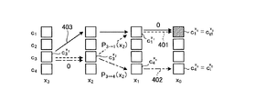
図4は、画素位置x0に向かって累積コストを計算する過程を説明する図である。図4の横軸は画素位置、縦軸は物体クラスをそれぞれ示している。画素位置xnは、画素位置x0から走査方向に対してn画素分戻った画素位置を示している。物体クラスの数は固定であり、ここでは4つの物体クラスc1〜c4(自動車・道路・歩行者・その他)があるものとしている。図4の例では、画素位置x3と画素位置x2の間と、画素位置x1と画素位置x0との間で物体クラスが変化しており、それぞれ遷移コストp’,p”が生じている。図中のEVは、画素位置x1と画素位置x0との間を拡大したものである。P2→1は、物体クラスc2から物体クラスc1への遷移コストである。 FIG. 4 is a diagram illustrating a process of calculating the cumulative cost toward the pixel position x 0 . The horizontal axis of FIG. 4 shows the pixel position, and the vertical axis shows the object class. The pixel position x n indicates a pixel position returned by n pixels with respect to the scanning direction from the pixel position x 0 . The number of objects class is fixed, here it is assumed that there are four object classes c 1 to c 4 (automobiles, roads, pedestrians and other). In the example of FIG. 4, the object class changes between the pixel position x 3 and the pixel position x 2 and between the pixel position x 1 and the pixel position x 0, and transition costs p'and p'are generated, respectively. EV in the figure is an enlargement between the pixel position x 1 and the pixel position x 0. P 2 → 1 is the transition cost from the object class c 2 to the object class c 1 .
累積コスト算出部13は、下記式(3)に従って、走査方向r毎に、画像の各画素における物体クラスc毎の累積コストLrを算出する。下記式(3)は、画素位置x0における物体クラスckの累積コストLr(x0,ck)を求める式である。
上記式(3)に示すように、画像の各画素における走査方向毎の累積コストは、走査方向に対して1つ戻った画素位置における累積コストと遷移コストを比較して最小になる物体クラスの累積コストを当該画素のベースコストに加算することで求められる。累積コスト算出部13は、画像上に設定した走査方向に沿って各画素の累積コストをベースコストに順次加算していくことで、画像の各画素における物体クラス毎の累積コストを算出する。
As shown in the above equation (3), the cumulative cost for each scanning direction in each pixel of the image is minimized by comparing the cumulative cost and the transition cost at the pixel position one step back with respect to the scanning direction. It is obtained by adding the cumulative cost to the base cost of the pixel. The cumulative
なお、この計算方法では、走査方向に沿って隣接画素間で累積コストを加算していくため、装置の演算処理能力によっては値がオーバーフローする懸念もある。このような場合には、下記式(4)に示すように、走査方向に対して1つ戻った画素位置における累積コストの最小値を減算したLr’をLrの代わりに用いてもよい。
走査方向毎に累積コストを求める上述の処理は他の走査方向との相互作用がないため、複数方向で並列して計算することが可能である。さらに、走査方向と平行な画素位置では相互作用がないため、位置に関しても並列に計算可能である。例えば、図3−1に示した例のように4つの走査方向を設定した場合には、走査方向201〜204で並列に計算でき、かつ、例えば走査方向201については、画像200の縦方向の画素分だけ並列に計算可能である。
Since the above-mentioned process of obtaining the cumulative cost for each scanning direction does not interact with other scanning directions, it is possible to calculate in parallel in a plurality of directions. Further, since there is no interaction at the pixel position parallel to the scanning direction, the position can be calculated in parallel. For example, when four scanning directions are set as in the example shown in FIG. 3-1 the
次に、累積コスト算出部13は、以上のように走査方向毎に算出した累積コストLrを下記式(5)に従って加算し、画像の各画素における物体クラス毎の統合累積コストLを求める。下記式(5)は、画素位置x0における物体クラスckの統合累積コストL(x0,ck)を求める式である。なお、画像上に設定された走査方向が1つのみであれば、統合累積コストL=累積コストLrである。
累積コスト算出部13により物体クラス毎の統合累積コストLが求められると、クラス決定部14が、画像の各画素において、下記式(6)に従って、統合累積コストLの値が最も小さい物体クラスを選択し、これを当該画素の物体クラスとして決定する。下記式(6)は、画素位置x0の物体クラスcx0を決定する式である。
以上のようにして、処理対象となる画像の各画素の物体クラスが決定されることにより、処理対象となる画像は画素毎に物体種別のラベリングが行われる。例えば、上述の自動運転の事例では、処理対象となる画像の各画素が「自動車」、「道路」、「歩行者」、「その他」のいずれかの物体ラベルでラベリングされ、画像における物体領域が識別される。 By determining the object class of each pixel of the image to be processed as described above, the image to be processed is labeled by the object type for each pixel. For example, in the above-mentioned example of automatic driving, each pixel of the image to be processed is labeled with an object label of "automobile", "road", "pedestrian", or "other", and the object area in the image is displayed. Be identified.
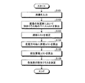
図5は、本実施形態に係る物体領域識別装置10の処理手順を示すフローチャートである。なお、図5の各ステップの具体的な内容は上述した通りであるので、詳細な説明は適宜省略する。
FIG. 5 is a flowchart showing a processing procedure of the object
処理対象となる画像が入力されると(ステップS101)、まず、ベースコスト算出部11が、ステップS101で入力された画像の各画素において予め定めた複数の物体クラス毎のベースコストを算出する(ステップS102)。
When the image to be processed is input (step S101), first, the base
次に、遷移コスト推定部12が、ステップS101で入力された画像上の隣接する画素間で物体クラスが遷移する際に要する遷移コストを推定する(ステップS103)。
Next, the transition
次に、累積コスト算出部13が、ステップS101で入力された画像上に設定した走査方向毎に、各画素の物体クラス毎の累積コストを算出する(ステップS104)。そして、累積コスト算出部13は、ステップS104で走査方向毎に算出した累積コストを加算して、統合累積コストを算出する(ステップS105)。
Next, the cumulative
次に、クラス決定部14が、ステップS101で入力された画像の各画素について、複数の物体クラスのうち、ステップS105で算出された統合累積コストの値が最も小さい物体クラスを、その画素の物体クラスとして決定する(ステップS106)。 Next, for each pixel of the image input in step S101, the class determination unit 14 selects the object class having the smallest integrated cumulative cost value calculated in step S105 among the plurality of object classes. Determined as a class (step S106).
以上説明したように、本実施形態に係る物体領域識別装置10は、大域的な情報を用いたセマンティックセグメンテーションを実現するにあたり、処理対象となる画像上に設定した走査方向毎に上記式(3)に従って各画素の物体クラス毎の累積コストを算出する。そして、複数の走査方向を設定した場合は、走査方向毎の累積コストを加算して統合累積コストを算出する。そして、画像の各画素において統合累積コスト(走査方向が1つの場合は累積コスト)の値が最も小さい物体クラスを、その画素の物体クラスとして決定する。したがって、従来技術のように繰り返しの計算を行うことなく1回の操作で各画素の物体クラスを決定することができ、大域的な情報を用いた高精度なラベリングをより少ない計算量で実現することができる。
As described above, the object
次に、上述の遷移コストを推定する遷移コスト推定部12がニューラルネットワークにより構成されている場合を想定し、この遷移コスト推定部12の具体的な学習方法について説明する。遷移コスト推定部12の学習時には、図6に示すように、クラス決定部14の代わりに更新部15が設けられ、累積コスト算出部13の出力が更新部15に入力される。更新部15は、累積コスト算出部13の出力が教示データに近づくように、遷移コスト推定部12を学習(ニューラルネットワークのネットワークパラメータを更新)する。
Next, assuming a case where the transition
教示データとは、画像に対応する正しいラベリング結果を示すデータである。画像と教示データとの組み合わせが学習用データである。学習用データの一例を図7に示す。図7に例示する学習用データは、図2で例示した画像100と、この画像100に対応する教示データ300とを含む。教示データ300は、画像100の自動車110が映る領域310内の各画素が「自動車」の物体ラベルでラベリングされ、画像100の道路120が映る領域320内の各画素が「道路」の物体ラベルでラベリングされ、その他の領域330内の各画素が「その他」の物体ラベルでラベリングされていることを示している。更新部15が遷移コスト推定部12を適切に学習するには、多数の学習用データが必要となる。
The teaching data is data showing the correct labeling result corresponding to the image. The combination of the image and the teaching data is the learning data. An example of learning data is shown in FIG. The learning data illustrated in FIG. 7 includes the
遷移コスト推定部12は、画素が隣接する方向に対して画像全体で固定値の遷移コストを推定するタイプと、画素位置の周辺のパタンに応じて変動する遷移コストを推定するタイプとの2つのタイプに大別される。前者のタイプの遷移コスト推定部12は、推定する遷移コストが固定値であるため、任意の正値を設定すればよい。遷移コストの決め方の1つの指針として、教示データに含まれる物体ラベル数に応じて決めればよい。すなわち、隣接する画素間で物体クラスが遷移する態様についてヒストグラムを作成し、出現頻度が大きい遷移に関しては相対的に小さい遷移コストを割り当て、出現頻度が小さい遷移に関しては相対的に大きい遷移コストを割り当てればよい。このため、前者のタイプの遷移コスト推定部12は、事前の学習が容易である。
The transition
しかし、実際には、画像パタンによって異なる遷移コストを与えるべきであると考えられる。例えば図2に示した画像例の画素103,104は典型的な道路に属する画像パタンとなっている。このような場合には、自動車から歩行者に遷移する際の遷移コストなど、最もらしからぬ遷移に対する遷移コストは大きくするべきである。後者のタイプの遷移コスト推定部12は、このような要求に応えるものであり、例えばニューラルネットワークを用いて実現することができる。
However, in reality, it is considered that different transition costs should be given depending on the image pattern. For example, the
以下では、後者のタイプの遷移コスト推定部12の具体的な学習方法について説明する。なお、遷移コスト推定部12を学習する際は、多数の学習用データを用いて、以下に示す遷移コスト推定部12の学習を繰り返し行う。
Hereinafter, a specific learning method of the latter type transition
遷移コスト推定部12の学習は、例えば、非特許文献4に開示される技術を応用して実施することができる。ただし、非特許文献4に開示される技術はステレオ画像を利用した視差画像の生成に関するものであり、これをそのまま適用することはできない。このため、新たに定式化を行う。この例の場合、まず、遷移コストの更新を行う画素位置を複数個選び出す。続いて、それらの画素位置を使って第1ロスおよび第2ロスを算出する。そして、これらの第1ロスおよび第2ロスに基づいて、遷移コスト推定部12を学習する。
The learning of the transition
図8は、遷移コスト推定部12を学習する際の処理手順を示すフローチャートである。以下、このフローチャートに沿って、遷移コスト推定部12の具体的な学習方法について詳しく説明する。
FIG. 8 is a flowchart showing a processing procedure when learning the transition
ステップS201では、遷移コストの更新を行う画素位置を画像から複数個選び出す。これらの画素位置は、画像内のすべての画素位置を選択してもよいが、現実的な計算速度で遷移コスト推定部12の学習を行うには、画像内から離散的に一部の画素位置を選び出せば十分である。
In step S201, a plurality of pixel positions for which the transition cost is updated are selected from the image. All the pixel positions in the image may be selected for these pixel positions, but in order to learn the transition
ステップS202では、第1ロスを算出する。さらに、遷移コスト推定部12は、ニューラルネットワークで構築されるため、一般的な学習手法である誤差逆伝播法(Backpropagation)に必要な微分も求める。
In step S202, the first loss is calculated. Further, since the transition
第1ロスは、下記式(7)に従って算出することができる。下記式(7)は、画素位置x0における走査方向rに対応する第1ロスH1(x0,r)を求める式である。
上記式(6)により、統合累積コストの値が最小となる物体クラスをその画素位置の物体クラスとして決定するため、真の物体クラスcgtはそれ以外の物体クラスciよりマージンm以上小さくなるように、ヒンジロスの形式で設計された上記式(7)に従って、第1ロスを算出する。なお、画素位置x0はステップS202で選択された画素位置である。上記式(7)では、走査方向rも考慮している。例えば、自動車はほとんどの場合、道路上に存在することから、例えば走査方向が下から上であるとき、物体クラスが自動車からその他に変わることはあるが、走査方向が上から下であるときに、物体クラスが自動車からその他になることはまれなはずである。走査方向rを考慮することにより、こうした傾向を遷移コスト推定部12の学習に反映させることができる。
The above equation (6) becomes smaller integration since the accumulated cost values to determine the object class with the smallest as the object class of the pixel positions, the true object class c gt margin m or more from the object class c i otherwise As described above, the first loss is calculated according to the above equation (7) designed in the form of hinge loss. The pixel position x 0 is the pixel position selected in step S202. In the above equation (7), the scanning direction r is also taken into consideration. For example, since automobiles are most often on the road, for example, when the scanning direction is from bottom to top, the object class may change from automobile to others, but when the scanning direction is from top to bottom. , Object classes should rarely change from automobiles to others. By considering the scanning direction r, such a tendency can be reflected in the learning of the transition
続いて、上記式(7)から、遷移コストに対する微分を求める。物体クラスの遷移の一例を図9に示す。図9に示す例では、画素位置x0で物体クラスc1が真の物体クラスcgtとなっている。ここで、画素位置x3から画素位置x0までの間で、物体クラスc3が物体クラスc1(=cgt)に遷移するパス401と、物体クラスc3が物体クラスc4(=ci)に遷移するパス402とを考える。これらのパス401,402の累積コストを上記式(3)に従って求める。すると、パス401の累積コストは下記式(8)、パス402の累積コストは下記式(9)でそれぞれ記述できる。
上記式(8)および上記式(9)を上記式(7)を代入し、下記式(10)の条件を満たす場合、遷移コストに対する微分は下記式(11)のように求めることができる。下記式(10)の条件を満たさない場合は、遷移コストに対する微分はすべて0である。
よって、微分が非0となる画素位置およびその遷移を保持しておき、後述のステップS204において遷移コスト推定部12を誤差逆伝播法により学習する際に、微分の値を利用することができる。
Therefore, the pixel position where the derivative is non-zero and the transition thereof are retained, and the value of the derivative can be used when learning the transition
ステップS203では、第2ロスを算出する。第1ロスは累積コストを計算する際の途中の画素位置における真の物体クラスを考慮していない。よって、遷移コストによっては、例えば図9に示すパス403のように、パス401とは異なるパスを通って真の物体クラスcgtに到達することもありえる。この場合、パス403の累積コストは下記式(12)のようになる。
上記式(12)と上記式(8)とを比べると、右辺第3項と第5項が異なっていることが分かる。これによって正しく遷移コストが求められないため、本ステップで第2コストを算出する。第2ロスの算出には2つの条件が必要である。1つめは、画素位置x0と画素位置x1の両方で真の物体クラスcgtが既知であること、2つめは、画素位置x1で累積コストが最小値をとる物体クラスが真の物体クラスcgtと一致していることである。これら2つの条件が満たされた画素位置に対して、下記式(13)により第2ロスを計算する。下記式(13)は、画素位置x0における走査方向rに対応する第2ロスH2(x0,r)を求める式である。
上記式(13)において、S(・)は、図10に示すパス501のように、画素位置x1における真の物体クラスcgtから画素位置x0で真の物体クラスcgtに到達するパスである。また、N(・)はそれ以外のパスであり、図10に示すパス群502のように、画素位置x1における真でない物体クラスciから画素位置x0で真の物体クラスcgtに到達するパス群と、図10に示すパス群503のように、画素位置x0で真でない物体クラスciに到達するパス群である。図10に示す例では、S(・)とN(・)はそれぞれ下記式(14)、下記式(15)のように記述できる。
第2ロスを求める上記式(13)から、第1ロスと同様に、遷移コストに対する微分を求めることができる。 From the above equation (13) for obtaining the second loss, the derivative with respect to the transition cost can be obtained in the same manner as for the first loss.
ステップS204では、ステップS202とステップS203で計算される第1ロスと第2ロスの双方を用いて、遷移コスト推定部12を学習する。例えば、第1ロスと第2ロスから、下記式(16)に示すようにロスHを作成する。そして、このロスHが小さくなるように、遷移コスト推定部12を学習する。
上記式(16)で示されるロスHは、第1ロスと第2ロスの組み合わせである。したがって、上述の第1ロスに関する遷移コストに対する微分の値と、第2ロスに関する遷移コストに対する微分の値とを用いて、遷移コスト推定部12を構成するニューラルネットワークを誤差逆伝播法により適切に学習(ネットワークパラメータを更新)することができる。
The loss H represented by the above formula (16) is a combination of the first loss and the second loss. Therefore, the neural network constituting the transition
遷移コスト推定部12の学習は、入力する学習用データを順次切り替えながら、累積コスト算出部13による累積コストの算出および図8のフローチャートに従った処理を繰り返す。学習の終了条件としては、例えば、所定回数以上の繰り返し回数を設定してもよいし、Validationデータを用いた検証によりセマンティックセグメンテーションのエラーが収束したと判断される場合に終了してもよい。
The learning of the transition
次に、遷移コスト推定部12の具体的な構造例について説明する。図11は、遷移コスト推定部12の具体的な構造の一例を示す図である。図11に示す遷移コスト推定部12は、画像パッチ601を入力とするニューラルネットワークである。画像パッチ601は、画素位置x0(注目画素)とその周辺の画像小領域である。画像パッチ601はマルチスケール化したり、カラー画像を入力したりしてもよい。また、画像パッチ601に加えて、画像全体における画像パッチ601の位置(注目画素の位置)を特定する位置情報602を遷移コスト推定部12の入力として用いてもよい。
Next, a specific structural example of the transition
例えば車載カメラにより撮影された画像では、画像の下方は道路の領域が多く、自動車は画像の中央付近に映るなど、分布に偏りがある。この情報を有効に利用するために、位置情報602をニューラルネットワークの入力の1つとして用いることが望ましい。
For example, in an image taken by an in-vehicle camera, there is a large amount of road area below the image, and an automobile appears near the center of the image, resulting in a biased distribution. In order to effectively use this information, it is desirable to use the
ニューラルネットワークの最終段603では、出力604を正値とするため、ELU(Exponential Linear Unit)と定数を足している。出力604が正値となるレイヤであればELUに限定されない。出力604は、物体クラスの遷移コストである。例えばN個の物体クラスがあり、M個の方向で遷移コストを推定する場合(走査方向がM個ある場合)の出力数は、N×(N−1)×Mである。
In the
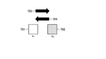
なお、図12に示すように、物体クラスc1に属する画素701と物体クラスc2に属する画素702がある場合、走査方向703に沿って物体クラスがc1からc2に遷移する際の遷移コストと、走査方向703と逆方向である走査方向704に沿って物体クラスがc2からc1に遷移する際の遷移コストとが同じになるように学習することで、出力604の数を半分に減らしてもよい。出力604の数を減らすことにより、計算時間をさらに短縮したり、学習に用いる学習用データの数を削減したりすることが期待できる。
Incidentally, as shown in FIG. 12, if there is a
図13は、遷移コスト推定部12の具体的な構造の他の例を示す図である。図13に示す遷移コスト推定部12は、ニューラルネットワークとして構成されることは図11の例と同様であるが、図11に示した画像パッチ601の代わりに別のニューラルネットワーク801の特徴量を入力として用いる。ニューラルネットワーク801として、例えばベースコスト算出部11として非特許文献1のニューラルネットワークを用いる場合は、このニューラルネットワークの特徴量をエンコードする部分(解像度を下げて畳み込み演算をすることにより計算された特徴量マップ)を用いることができる。すなわち、ベースコスト算出部11の中間出力である特徴量を、遷移コスト推定部12の入力として用いることができる。遷移コスト推定部12の入力は、画素位置ごとに異なる特徴量となっていることが望ましい。非特許文献1のニューラルネットワークでは、低解像度から高解像度までマルチスケールの情報を用いることができる。
FIG. 13 is a diagram showing another example of the specific structure of the transition
また、図11の例と同様に、画像全体における画素位置を特定する位置情報802を特徴量と併せて遷移コスト推定部12に入力するようにしてもよい。さらに、これ以外にも遷移コスト推定部12の入力として、画像が撮影された場所、地域、時間、天候、カメラの種類などの情報を用いたり、RGB画像以外にも深度を加えたRGBDや深度画像のみや、赤外画像などを用いたりしてもよい。ニューラルネットワークの最終段803は、図11の例と同様であり、物体クラスの遷移コストを出力804とする。
Further, as in the example of FIG. 11, the
図14は、図13に示す構造の遷移コスト推定部12を用いた場合の物体領域識別装置10の構成例を示す図である。図14に示す物体領域識別装置10は、入力画像901の各画素における物体クラス毎のベースコストをベースコスト算出部11で算出する。また、大域的な情報を用いるため、ベースコスト算出部11の中間出力である特徴量を用いて、遷移コスト推定部12において物体クラス間の遷移コストを推定する。そして、ベースコスト算出部11の出力と遷移コスト推定部12の出力とを用いて、累積コスト算出部13において各画素における物体クラス毎の累積コストを算出する。走査方向が複数ある場合は、走査方向毎の累積コストを加算して統合累積コストを算出する。そして、累積コスト算出部13の出力を用いて、クラス決定部14において入力画像901の各画素の物体クラスを決定し、入力画像901に対応するラベリング結果(セマンティックセグメンテーションの結果)902を出力する。
FIG. 14 is a diagram showing a configuration example of the object
上述の特許文献1や非特許文献2で開示される従来の手法により推定されるペナルティ(ペアワイズ項)は、ガウス関数にRGBで表現される画素値や画素位置の距離などを入力し、その標準偏差や複数のガウス関数の重みで調整した後、画像特徴に関係なく決まっている物体クラス間の重みであるCompatibilityを最後に掛け合わせ算出したものである。ところが物体クラス間の重みは画像特徴と相関があるため、従来手法により推定されるペナルティは十分な表現能力がない。これに対し、本実施形態に係る物体領域識別装置10の遷移コスト推定部12は、入力された画像パッチやニューラルネットワークの中間出力である特徴量に対して、特徴量を改めて自動で学習し、学習された特徴量から遷移コスト(ペナルティに相当)を直接推定するため、十分な表現能力を持つ。すなわち、本実施形態では、従来手法のようにCompatibilityを分離する必要がなく、画素値ではなく画像のパタンも同時に考慮されるため、従来手法よりも遷移コストを適切に推定することができる。
The penalty (pairwise term) estimated by the conventional method disclosed in
上述した本実施形態に係る物体領域識別装置10は、例えば、汎用のコンピュータ装置を基本ハードウェアとして用いることで実現することが可能である。すなわち、上述の物体領域識別装置10の各部の機能は、汎用のコンピュータ装置に搭載された1以上のプロセッサにプログラムを実行させることにより実現することができる。このとき、物体領域識別装置10は、上記のプログラムをコンピュータ装置にあらかじめインストールすることで実現してもよいし、CD−ROMなどの記憶媒体に記憶して、あるいはネットワークを介して上記のプログラムを配布して、このプログラムをコンピュータ装置に適宜インストールすることで実現してもよい。
The object
図15は、本実施形態に係る物体領域識別装置10のハードウェア構成例を示すブロック図である。物体領域識別装置10は、例えば図15に示すように、CPU(Central Processing Unit)などのプロセッサ21と、RAM(Random Access Memory)やROM(Read Only Memory)などのメモリ22と、HDD(Hard Disk Drive)やSSD(Solid State Drive)などのストレージデバイス23と、液晶パネルなどの表示装置26や画像を撮影するカメラ27といった機器を接続するための機器I/F24と、装置外部と通信を行う通信I/F25と、これら各部を接続するバス28とを備えた一般的なコンピュータとしてのハードウェア構成を有する。
FIG. 15 is a block diagram showing a hardware configuration example of the object
物体領域識別装置10が図15のようなハードウェア構成を有する場合、例えば、プロセッサ21がメモリ22を利用して、ストレージデバイス23などに格納されたプログラムを読み出して実行することにより、上述の各部(ベースコスト算出部11、遷移コスト推定部12、累積コスト算出部13、クラス決定部14(更新部15))の機能を実現することができる。
When the object
なお、上述の物体領域識別装置10の各部の機能は、その一部または全部を、ASIC(Application Specific Integrated Circuit)やFPGA(Field-Programmable Gate Array)などの専用のハードウェア(汎用のプロセッサではなく専用のプロセッサ)により実現することもできる。また、複数のプロセッサを用いて上述した各部の機能を実現する構成であってもよい。
It should be noted that the functions of each part of the object
また、本実施形態に係る物体領域識別装置10は、複数台のコンピュータ装置を用い、上述の各部の機能を複数台のコンピュータ装置に分散して実現した物体領域識別システムとして構成してもよい。また、本実施形態に係る物体領域識別装置10は、クラウドシステム上で動作する仮想マシンであってもよい。
Further, the object
以上、本発明の実施形態を説明したが、ここで説明した実施形態は、例として提示したものであり、発明の範囲を限定することは意図していない。ここで説明した新規な実施形態は、その他の様々な形態で実施されることが可能であり、発明の要旨を逸脱しない範囲で、種々の省略、置き換え、変更を行うことができる。ここで説明した実施形態やその変形は、発明の範囲や要旨に含まれるとともに、特許請求の範囲に記載された発明とその均等の範囲に含まれる。 Although the embodiments of the present invention have been described above, the embodiments described here are presented as examples and are not intended to limit the scope of the invention. The novel embodiment described here can be implemented in various other forms, and various omissions, replacements, and changes can be made without departing from the gist of the invention. The embodiments and modifications thereof described here are included in the scope and gist of the invention, and are also included in the scope of the invention described in the claims and the equivalent scope thereof.
10 物体領域識別装置
11 ベースコスト算出部
12 遷移コスト推定部
13 累積コスト算出部
14 クラス決定部
15 更新部
10 Object
Claims (10)
前記各画素において前記複数の物体クラス毎のベースコストを算出するベースコスト算出部と、
前記画像上の隣接する画素間で物体クラスが遷移する際に要する遷移コストを推定する遷移コスト推定部と、
前記画像上に設定した走査方向に沿って、前記ベースコストと前記遷移コストを前記複数の物体クラス毎に累積して、前記各画素における前記複数の物体クラス毎の累積コストを算出する累積コスト算出部と、
前記累積コストに基づいて、前記各画素の物体クラスを決定するクラス決定部と、
を備える物体領域識別装置。 It is an object area identification device that identifies which of a plurality of predetermined object classes each pixel of an image belongs to and labels the object type for each pixel.
A base cost calculation unit that calculates the base cost for each of the plurality of object classes in each pixel,
A transition cost estimation unit that estimates the transition cost required when the object class transitions between adjacent pixels on the image,
Cumulative cost calculation for calculating the cumulative cost for each of the plurality of object classes in each pixel by accumulating the base cost and the transition cost for each of the plurality of object classes along the scanning direction set on the image. Department and
A class determination unit that determines the object class of each pixel based on the cumulative cost,
An object area identification device comprising.
前記クラス決定部は、前記各画素において、前記複数の物体クラスのうち、前記複数の走査方向毎に算出した前記累積コストを加算した統合累積コストの値が最も小さい物体クラスを、当該画素の物体クラスとして決定する
請求項1に記載の物体領域識別装置。 The cumulative cost calculation unit estimates the transition cost for each of the plurality of object classes for each of the plurality of scanning directions set on the image.
In each of the pixels, the class determination unit selects the object class having the smallest integrated cumulative cost value, which is the sum of the cumulative costs calculated for each of the plurality of scanning directions, among the plurality of object classes. The object area identification device according to claim 1, which is determined as a class.
請求項1または2に記載の物体領域識別装置。 The object area identification device according to claim 1 or 2, wherein the calculation of the cumulative cost by the cumulative cost calculation unit and the determination of the object class by the class determination unit are performed by using a dynamic programming method.
請求項1乃至3のいずれか一項に記載の物体領域識別装置。 Any of claims 1 to 3 in which the transition cost estimation unit is trained using training data so as to estimate the transition cost so that the cumulative cost in each pixel is minimized in the true object class. The object area identification device according to item 1.
請求項4に記載の物体領域識別装置。 The object area identification device according to claim 4, wherein the transition cost estimation unit is composed of a neural network.
請求項1乃至5のいずれか一項に記載の物体領域識別装置。 The object according to any one of claims 1 to 5, wherein the transition cost estimation unit receives the pixel of interest of the image and a small image region around the pixel as input, and estimates and outputs the transition cost of the pixel of interest. Area identification device.
請求項1乃至5のいずれか一項に記載の物体領域識別装置。 The object according to any one of claims 1 to 5, wherein the transition cost estimation unit receives a feature amount calculated by another neural network as an input, estimates and outputs the transition cost in the pixel of interest of the image. Area identification device.
請求項6または7に記載の物体領域識別装置。 The object area identification device according to claim 6 or 7, wherein the transition cost estimation unit further inputs position information for identifying the pixel of interest on the image.
前記各画素において前記複数の物体クラス毎のベースコストを算出し、
前記画像上の隣接する画素間で物体クラスが遷移する際に要する遷移コストを推定し、
前記画像上に設定した走査方向に沿って、前記ベースコストと前記遷移コストを前記複数の物体クラス毎に累積して、前記各画素における前記複数の物体クラス毎の累積コストを算出し、
前記累積コストに基づいて、前記各画素の物体クラスを決定する
物体領域識別方法。 It is an object area identification method that identifies which of a plurality of predetermined object classes each pixel of an image belongs to and labels the object type for each pixel.
For each pixel, the base cost for each of the plurality of object classes is calculated.
Estimate the transition cost required for the object class to transition between adjacent pixels on the image.
The base cost and the transition cost are accumulated for each of the plurality of object classes along the scanning direction set on the image, and the cumulative cost for each of the plurality of object classes in each pixel is calculated.
An object area identification method for determining an object class for each pixel based on the cumulative cost.
前記コンピュータに、
前記各画素において前記複数の物体クラス毎のベースコストを算出する機能と、
前記画像上の隣接する画素間で物体クラスが遷移する際に要する遷移コストを推定する機能と、
前記画像上に設定した走査方向に沿って、前記ベースコストと前記遷移コストを前記複数の物体クラス毎に累積して、前記各画素における前記複数の物体クラス毎の累積コストを算出する機能と、
前記累積コストに基づいて、前記各画素の物体クラスを決定する機能と、
を実現させるためのプログラム。 A program for causing a computer to function as an object area identification device that identifies which of a plurality of predetermined object classes each pixel of an image belongs to and labels each object type for each pixel.
On the computer
A function to calculate the base cost for each of the plurality of object classes in each pixel, and
A function for estimating the transition cost required when the object class transitions between adjacent pixels on the image, and
A function of accumulating the base cost and the transition cost for each of the plurality of object classes along the scanning direction set on the image, and calculating the cumulative cost for each of the plurality of object classes in each pixel.
A function to determine the object class of each pixel based on the cumulative cost, and
A program to realize.
Priority Applications (2)
| Application Number | Priority Date | Filing Date | Title |
|---|---|---|---|
| JP2018039979A JP6800901B2 (en) | 2018-03-06 | 2018-03-06 | Object area identification device, object area identification method and program |
| US16/117,891 US10853657B2 (en) | 2018-03-06 | 2018-08-30 | Object region identifying apparatus, object region identifying method, and computer program product |
Applications Claiming Priority (1)
| Application Number | Priority Date | Filing Date | Title |
|---|---|---|---|
| JP2018039979A JP6800901B2 (en) | 2018-03-06 | 2018-03-06 | Object area identification device, object area identification method and program |
Publications (2)
| Publication Number | Publication Date |
|---|---|
| JP2019153235A JP2019153235A (en) | 2019-09-12 |
| JP6800901B2 true JP6800901B2 (en) | 2020-12-16 |
Family
ID=67843363
Family Applications (1)
| Application Number | Title | Priority Date | Filing Date |
|---|---|---|---|
| JP2018039979A Active JP6800901B2 (en) | 2018-03-06 | 2018-03-06 | Object area identification device, object area identification method and program |
Country Status (2)
| Country | Link |
|---|---|
| US (1) | US10853657B2 (en) |
| JP (1) | JP6800901B2 (en) |
Families Citing this family (2)
| Publication number | Priority date | Publication date | Assignee | Title |
|---|---|---|---|---|
| JP7544338B2 (en) * | 2019-09-27 | 2024-09-04 | 国立大学法人 東京大学 | Information processing device, information processing system, information processing method, and program |
| WO2022070574A1 (en) * | 2020-09-29 | 2022-04-07 | 富士フイルム株式会社 | Information processing device, information processing method, and information processing program |
Family Cites Families (16)
| Publication number | Priority date | Publication date | Assignee | Title |
|---|---|---|---|---|
| US5787274A (en) * | 1995-11-29 | 1998-07-28 | International Business Machines Corporation | Data mining method and system for generating a decision tree classifier for data records based on a minimum description length (MDL) and presorting of records |
| DE69721913T2 (en) * | 1996-03-13 | 2004-05-13 | Koninklijke Philips Electronics N.V. | FILTERING METHOD AND RELATED FILTERING SYSTEM |
| US5870735A (en) * | 1996-05-01 | 1999-02-09 | International Business Machines Corporation | Method and system for generating a decision-tree classifier in parallel in a multi-processor system |
| EP0990222B1 (en) * | 1998-04-03 | 2003-06-04 | Koninklijke Philips Electronics N.V. | Image processing method and system involving contour detection steps |
| US6363319B1 (en) * | 1999-08-31 | 2002-03-26 | Nortel Networks Limited | Constraint-based route selection using biased cost |
| AUPQ921800A0 (en) * | 2000-08-04 | 2000-08-31 | Canon Kabushiki Kaisha | A method for automatic segmentation of image data from multiple data sources |
| US6661842B1 (en) * | 2000-09-22 | 2003-12-09 | General Dynamics Decision Systems, Inc. | Methods and apparatus for error-resilient video coding |
| TW571248B (en) * | 2001-10-11 | 2004-01-11 | Exscientia Llc | Method and apparatus for learning to classify patterns and assess the value of decisions |
| GB2399245B (en) * | 2003-03-03 | 2005-07-27 | Motorola Inc | Method for segmenting an image and an image transmission system and image transmission unit therefor |
| GB0502371D0 (en) * | 2005-02-04 | 2005-03-16 | British Telecomm | Identifying spurious regions in a video frame |
| GB0502369D0 (en) * | 2005-02-04 | 2005-03-16 | British Telecomm | Classifying an object in a video frame |
| JP2008217706A (en) | 2007-03-07 | 2008-09-18 | Tokyo Institute Of Technology | Labeling device, labeling method and program |
| EP2105874A1 (en) * | 2008-03-27 | 2009-09-30 | British Telecommunications Public Limited Company | Multi-site service charging protocol |
| EP2851869A4 (en) * | 2012-05-18 | 2016-03-30 | Nec Solution Innovators Ltd | Fingerprint ridge image synthesis system, fingerprint ridge image synthesis method, and program thereof |
| US9704257B1 (en) * | 2016-03-25 | 2017-07-11 | Mitsubishi Electric Research Laboratories, Inc. | System and method for semantic segmentation using Gaussian random field network |
| JP2018014041A (en) * | 2016-07-22 | 2018-01-25 | 日本電信電話株式会社 | Labeling device, labeling method and labeling program |
-
2018
- 2018-03-06 JP JP2018039979A patent/JP6800901B2/en active Active
- 2018-08-30 US US16/117,891 patent/US10853657B2/en active Active
Also Published As
| Publication number | Publication date |
|---|---|
| US20190278998A1 (en) | 2019-09-12 |
| JP2019153235A (en) | 2019-09-12 |
| US10853657B2 (en) | 2020-12-01 |
Similar Documents
| Publication | Publication Date | Title |
|---|---|---|
| US20240161622A1 (en) | Vehicle environment modeling with a camera | |
| Vaudrey et al. | Differences between stereo and motion behaviour on synthetic and real-world stereo sequences | |
| CN113377888B (en) | Method for training object detection model and detection object | |
| US20210398301A1 (en) | Camera agnostic depth network | |
| WO2020151167A1 (en) | Target tracking method and device, computer device and readable storage medium | |
| US8712096B2 (en) | Method and apparatus for detecting and tracking vehicles | |
| CN104517275A (en) | Object detection method and system | |
| CN114119749B (en) | A monocular 3D vehicle detection method based on dense association | |
| US20240101158A1 (en) | Determining a location of a target vehicle relative to a lane | |
| JP2020080047A (en) | Learning device, estimating device, learning method and program | |
| Liu et al. | Vehicle detection and ranging using two different focal length cameras | |
| US20230154198A1 (en) | Computer-implemented method for multimodal egocentric future prediction | |
| CN113793364A (en) | Target tracking method and device, computer equipment and storage medium | |
| Rawashdeh et al. | Camera–Lidar sensor fusion for drivable area detection in winter weather using convolutional neural networks | |
| Milli et al. | Multi-modal multi-task (3mt) road segmentation | |
| CN113902047B (en) | Image element matching method, device, equipment and storage medium | |
| CN116663650A (en) | Training method of deep learning model, target object detection method and device | |
| CN110211190B (en) | Method and device for training camera self-motion parameter estimation model and storage medium | |
| JP6800901B2 (en) | Object area identification device, object area identification method and program | |
| CN121415331B (en) | A general visual model training method and system | |
| CN111126327B (en) | Lane line detection method, system, vehicle-mounted system and vehicle | |
| CN119964129B (en) | Target detection optimization method and system based on Center Point model | |
| Ramtoula et al. | Msl-raptor: A 6dof relative pose tracker for onboard robotic perception | |
| CN117237612B (en) | A target detection method for complex road scenes based on YOLOX model | |
| CN115546784B (en) | 3D target detection method based on deep learning |
Legal Events
| Date | Code | Title | Description |
|---|---|---|---|
| A621 | Written request for application examination |
Free format text: JAPANESE INTERMEDIATE CODE: A621 Effective date: 20190816 |
|
| A977 | Report on retrieval |
Free format text: JAPANESE INTERMEDIATE CODE: A971007 Effective date: 20201009 |
|
| TRDD | Decision of grant or rejection written | ||
| A01 | Written decision to grant a patent or to grant a registration (utility model) |
Free format text: JAPANESE INTERMEDIATE CODE: A01 Effective date: 20201027 |
|
| A61 | First payment of annual fees (during grant procedure) |
Free format text: JAPANESE INTERMEDIATE CODE: A61 Effective date: 20201125 |
|
| R151 | Written notification of patent or utility model registration |
Ref document number: 6800901 Country of ref document: JP Free format text: JAPANESE INTERMEDIATE CODE: R151 |