JP6801846B2 - 3D holographic imaging flow cytometry - Google Patents
3D holographic imaging flow cytometry Download PDFInfo
- Publication number
- JP6801846B2 JP6801846B2 JP2015556256A JP2015556256A JP6801846B2 JP 6801846 B2 JP6801846 B2 JP 6801846B2 JP 2015556256 A JP2015556256 A JP 2015556256A JP 2015556256 A JP2015556256 A JP 2015556256A JP 6801846 B2 JP6801846 B2 JP 6801846B2
- Authority
- JP
- Japan
- Prior art keywords
- sample
- light
- detected
- flow channel
- imaging system
- Prior art date
- Legal status (The legal status is an assumption and is not a legal conclusion. Google has not performed a legal analysis and makes no representation as to the accuracy of the status listed.)
- Active
Links
Images







Classifications
-
- G—PHYSICS
- G01—MEASURING; TESTING
- G01N—INVESTIGATING OR ANALYSING MATERIALS BY DETERMINING THEIR CHEMICAL OR PHYSICAL PROPERTIES
- G01N15/00—Investigating characteristics of particles; Investigating permeability, pore-volume or surface-area of porous materials
- G01N15/10—Investigating individual particles
- G01N15/14—Optical investigation techniques, e.g. flow cytometry
- G01N15/1434—Optical arrangements
-
- G—PHYSICS
- G01—MEASURING; TESTING
- G01N—INVESTIGATING OR ANALYSING MATERIALS BY DETERMINING THEIR CHEMICAL OR PHYSICAL PROPERTIES
- G01N15/00—Investigating characteristics of particles; Investigating permeability, pore-volume or surface-area of porous materials
- G01N15/10—Investigating individual particles
- G01N15/14—Optical investigation techniques, e.g. flow cytometry
- G01N15/1429—Signal processing
- G01N15/1433—Signal processing using image recognition
-
- G—PHYSICS
- G01—MEASURING; TESTING
- G01N—INVESTIGATING OR ANALYSING MATERIALS BY DETERMINING THEIR CHEMICAL OR PHYSICAL PROPERTIES
- G01N21/00—Investigating or analysing materials by the use of optical means, i.e. using sub-millimetre waves, infrared, visible or ultraviolet light
- G01N21/17—Systems in which incident light is modified in accordance with the properties of the material investigated
- G01N21/47—Scattering, i.e. diffuse reflection
- G01N21/49—Scattering, i.e. diffuse reflection within a body or fluid
- G01N21/53—Scattering, i.e. diffuse reflection within a body or fluid within a flowing fluid, e.g. smoke
-
- G—PHYSICS
- G01—MEASURING; TESTING
- G01N—INVESTIGATING OR ANALYSING MATERIALS BY DETERMINING THEIR CHEMICAL OR PHYSICAL PROPERTIES
- G01N21/00—Investigating or analysing materials by the use of optical means, i.e. using sub-millimetre waves, infrared, visible or ultraviolet light
- G01N21/62—Systems in which the material investigated is excited whereby it emits light or causes a change in wavelength of the incident light
- G01N21/63—Systems in which the material investigated is excited whereby it emits light or causes a change in wavelength of the incident light optically excited
- G01N21/64—Fluorescence; Phosphorescence
-
- G—PHYSICS
- G03—PHOTOGRAPHY; CINEMATOGRAPHY; ANALOGOUS TECHNIQUES USING WAVES OTHER THAN OPTICAL WAVES; ELECTROGRAPHY; HOLOGRAPHY
- G03H—HOLOGRAPHIC PROCESSES OR APPARATUS
- G03H1/00—Holographic processes or apparatus using light, infrared or ultraviolet waves for obtaining holograms or for obtaining an image from them; Details peculiar thereto
- G03H1/04—Processes or apparatus for producing holograms
- G03H1/0443—Digital holography, i.e. recording holograms with digital recording means
-
- G—PHYSICS
- G03—PHOTOGRAPHY; CINEMATOGRAPHY; ANALOGOUS TECHNIQUES USING WAVES OTHER THAN OPTICAL WAVES; ELECTROGRAPHY; HOLOGRAPHY
- G03H—HOLOGRAPHIC PROCESSES OR APPARATUS
- G03H1/00—Holographic processes or apparatus using light, infrared or ultraviolet waves for obtaining holograms or for obtaining an image from them; Details peculiar thereto
- G03H1/04—Processes or apparatus for producing holograms
- G03H1/08—Synthesising holograms, i.e. holograms synthesized from objects or objects from holograms
- G03H1/0866—Digital holographic imaging, i.e. synthesizing holobjects from holograms
-
- G—PHYSICS
- G01—MEASURING; TESTING
- G01N—INVESTIGATING OR ANALYSING MATERIALS BY DETERMINING THEIR CHEMICAL OR PHYSICAL PROPERTIES
- G01N15/00—Investigating characteristics of particles; Investigating permeability, pore-volume or surface-area of porous materials
- G01N15/10—Investigating individual particles
- G01N15/14—Optical investigation techniques, e.g. flow cytometry
- G01N15/1484—Optical investigation techniques, e.g. flow cytometry microstructural devices
-
- G—PHYSICS
- G01—MEASURING; TESTING
- G01N—INVESTIGATING OR ANALYSING MATERIALS BY DETERMINING THEIR CHEMICAL OR PHYSICAL PROPERTIES
- G01N15/00—Investigating characteristics of particles; Investigating permeability, pore-volume or surface-area of porous materials
- G01N15/10—Investigating individual particles
- G01N15/14—Optical investigation techniques, e.g. flow cytometry
- G01N15/1434—Optical arrangements
- G01N2015/144—Imaging characterised by its optical setup
- G01N2015/1445—Three-dimensional imaging, imaging in different image planes, e.g. under different angles or at different depths, e.g. by a relative motion of sample and detector, for instance by tomography
-
- G—PHYSICS
- G03—PHOTOGRAPHY; CINEMATOGRAPHY; ANALOGOUS TECHNIQUES USING WAVES OTHER THAN OPTICAL WAVES; ELECTROGRAPHY; HOLOGRAPHY
- G03H—HOLOGRAPHIC PROCESSES OR APPARATUS
- G03H1/00—Holographic processes or apparatus using light, infrared or ultraviolet waves for obtaining holograms or for obtaining an image from them; Details peculiar thereto
- G03H1/0005—Adaptation of holography to specific applications
- G03H2001/0033—Adaptation of holography to specific applications in hologrammetry for measuring or analysing
-
- G—PHYSICS
- G03—PHOTOGRAPHY; CINEMATOGRAPHY; ANALOGOUS TECHNIQUES USING WAVES OTHER THAN OPTICAL WAVES; ELECTROGRAPHY; HOLOGRAPHY
- G03H—HOLOGRAPHIC PROCESSES OR APPARATUS
- G03H1/00—Holographic processes or apparatus using light, infrared or ultraviolet waves for obtaining holograms or for obtaining an image from them; Details peculiar thereto
- G03H1/0005—Adaptation of holography to specific applications
- G03H2001/005—Adaptation of holography to specific applications in microscopy, e.g. digital holographic microscope [DHM]
-
- G—PHYSICS
- G03—PHOTOGRAPHY; CINEMATOGRAPHY; ANALOGOUS TECHNIQUES USING WAVES OTHER THAN OPTICAL WAVES; ELECTROGRAPHY; HOLOGRAPHY
- G03H—HOLOGRAPHIC PROCESSES OR APPARATUS
- G03H1/00—Holographic processes or apparatus using light, infrared or ultraviolet waves for obtaining holograms or for obtaining an image from them; Details peculiar thereto
- G03H1/04—Processes or apparatus for producing holograms
- G03H1/0443—Digital holography, i.e. recording holograms with digital recording means
- G03H2001/0445—Off-axis recording arrangement
-
- G—PHYSICS
- G03—PHOTOGRAPHY; CINEMATOGRAPHY; ANALOGOUS TECHNIQUES USING WAVES OTHER THAN OPTICAL WAVES; ELECTROGRAPHY; HOLOGRAPHY
- G03H—HOLOGRAPHIC PROCESSES OR APPARATUS
- G03H2210/00—Object characteristics
- G03H2210/10—Modulation characteristics, e.g. amplitude, phase, polarisation
- G03H2210/12—Phase modulating object, e.g. living cell
Landscapes
- Chemical & Material Sciences (AREA)
- General Physics & Mathematics (AREA)
- Physics & Mathematics (AREA)
- Health & Medical Sciences (AREA)
- Biochemistry (AREA)
- General Health & Medical Sciences (AREA)
- Pathology (AREA)
- Immunology (AREA)
- Life Sciences & Earth Sciences (AREA)
- Analytical Chemistry (AREA)
- Engineering & Computer Science (AREA)
- Dispersion Chemistry (AREA)
- Theoretical Computer Science (AREA)
- Computing Systems (AREA)
- Signal Processing (AREA)
- Nuclear Medicine, Radiotherapy & Molecular Imaging (AREA)
- Investigating Or Analysing Materials By Optical Means (AREA)
- Holo Graphy (AREA)
- Microscoopes, Condenser (AREA)
- Computer Vision & Pattern Recognition (AREA)
Description
本発明は、3Dホログラフィックイメージングフローサイトメトリに関する。
[関連出願への参照]
本出願は、2013年2月5日に出願された米国仮特許出願第61/761、079号に関連し、それに基づく優先権を主張する。当該出願の全開示は、本明細書に参照により全体として組み込まれる。
The present invention relates to 3D holographic imaging flow cytometry.
[Reference to related applications]
This application relates to US Provisional Patent Application Nos. 61/761, 079 filed on February 5, 2013 and claims priority based thereto. The entire disclosure of such application is incorporated herein by reference in its entirety.
[政府のサポート]
本発明は、アメリカ国立衛生研究所により授けられた、付与第EB015871号の下、政府のサポートとともになされた。政府は、本発明において複数の特定の権利を有する。
[背景技術]
[Government support]
The present invention was made with government support under Grant No. EB015871 awarded by the National Institutes of Health. Government has a number of specific rights in the present invention.
[Background technology]
フローサイトメトリは、液体のストリームを流れる多数の細胞を調べるテクノロジであり、通常、光学スペクトルスコピーと組み合わされる。フローサイトメトリは、ゲノムレベルにまでおける細胞の特性評価を可能にする。フローサイトメトリにおけるコントラストメカニズムは、遺伝子操作によって外部的に管理または生成された蛍光である。しかしながら、最も自然な状況において、複数の生物標本を観察するには、標本の複数の固有特性を利用する、汚染のない複数の方法が好ましい。さらに、蛍光標識は、とりわけ複数の一次細胞に対し、必ずしも実行可能な選択肢ではない。複数の標識薬剤の光退色および不均一なバインディングは通常、複数の標的分子を正確に定量化するのを難しくする。 Flow cytometry is a technology that examines a large number of cells flowing through a stream of liquid and is usually combined with an optical spectral scan. Flow cytometry enables characterization of cells down to the genomic level. The contrast mechanism in flow cytometry is fluorescence that is externally controlled or generated by genetic manipulation. However, in the most natural situations, for observing multiple biological specimens, multiple pollution-free methods that utilize multiple intrinsic properties of the specimens are preferred. Moreover, fluorescent labeling is not always a viable option, especially for multiple primary cells. Photobleaching and heterogeneous binding of multiple labeling agents usually make it difficult to accurately quantify multiple target molecules.
屈折率は、光干渉断層撮影および光散乱分光法を含む、様々な画像診断法における、固有コントラストソースとして機能する。同時に、屈折率は、複数の有機分子の密度に関連付けられ得、その体積積分は、細胞内または複数の細胞器官内の非水の合計内容量を提供し得る。複数の細胞の屈折率における変動および変化は、複数の発癌形質転換に結び付けられてきた。複数の均質バルク材の屈折率は、既知の屈折率を有する他の物質に対し、標本の臨界角を測定する、臨界角屈折計を使用して取得され得る。複数の薄膜層物質については、入射光のエリプソメトリ測定脱分極が精密であるとして既知である。しかしながら、複数の生物学的細胞のような非均質な標本の屈折率は、より細心の扱いを要求する。 The index of refraction serves as an intrinsic contrast source in various diagnostic imaging methods, including optical coherence tomography and light scattering spectroscopy. At the same time, the index of refraction can be associated with the density of multiple organic molecules, the volume integral of which can provide the total volume of non-water within the cell or organelles. Fluctuations and changes in the refractive index of multiple cells have been linked to multiple carcinogenic transformations. The index of refraction of a plurality of homogeneous bulk materials can be obtained using a critical angle refractometer, which measures the critical angle of the specimen relative to other materials with known refractive indexes. For multiple thin film layer materials, ellipsometry measurement depolarization of incident light is known to be precise. However, the index of refraction of non-homogeneous specimens, such as multiple biological cells, requires more meticulous treatment.
断層撮影位相差顕微鏡(TPM)は、複数の生体細胞内の屈折率の3Dマッピングを可能にする新規な技術である。TPMの最近の複数の開発は、細胞内レベルにおける複数の生体細胞の生理学的状態に係る汚染のない監視を約束する。通常、屈折率の断層イメージングは、標本上の様々な照明角度における複数のイメージの記録を要求する。従って、既存の複数の方法は、データ取得中に固定されている標本に対する照明角度を変更するための複数の移動要素を有していたか、あるいは標本を回転させていた。結果的に、断層イメージングのスループットは通常低く、それによりTPMが日常の生物学的研究に使用されるのを妨げてきた。 Computed tomography phase contrast microscopy (TPM) is a novel technique that enables 3D mapping of refractive indexes in multiple living cells. Recent developments of the TPM promise uncontaminated monitoring of the physiological status of multiple living cells at the intracellular level. Refractive index tomographic imaging typically requires the recording of multiple images at different illumination angles on the specimen. Therefore, existing methods either had multiple moving elements to change the illumination angle for a fixed specimen during data acquisition, or rotated the specimen. As a result, tomographic imaging throughput is usually low, which has prevented TPM from being used in routine biological research.
屈折率は、物質内の光波の速度に関連付けられることができる。従って、標本による波面歪は、標本によって誘発される光波の全位相(時間)遅延を表す。波面歪は、シャックハルトマンの波面センサ、干渉法、またはインラインホログラフィ(または伝播ベースの複数の方法とも呼ばれる)で測定され得る。これらの技術の中で、干渉法は光レジームにおいて特に適切であり、そこでは、相当大きなコヒーレンス長を持つ複数の光源が容易に利用可能である。位相遅延は、標本の光学経路の長さ、光の伝播方向に沿った屈折率の積分に比例する。従って、本明細書に記載の通り、波面測定と連携して、断層撮影再構成アルゴリズムを使用することで、深さ分解屈折率マップが取得されてよい。断層撮影屈折率測定は通常、X線コンピュータ断層撮影のように、試料への入射角が変化される、コリメートされたレーザビームを使用して実行される。あるいは、屈折率マップは、空間的インコヒーレントビームを使用すること、および試料の対物フォーカスをスキャンすることで取得されてよい。しかしながら、いずれのアプローチにおいても、照明方向または対物フォーカスが変化される間、試料は固定されている必要があり、それにより、イメージングのスループットを制限する。 Refractive index can be associated with the velocity of light waves in a substance. Therefore, the wave surface distortion due to the sample represents the full phase (time) delay of the light wave induced by the sample. Wavefront distortion can be measured with Shack-Hartmann wavefront sensors, interferometry, or in-line holography (also referred to as propagation-based multiple methods). Among these techniques, interferometry is particularly suitable in optical regimes, where multiple light sources with fairly large coherence lengths are readily available. The phase delay is proportional to the length of the optical path of the specimen and the integral of the index of refraction along the direction of light propagation. Therefore, as described herein, a depth-resolved refractive index map may be obtained by using a computed tomography reconstruction algorithm in conjunction with wave surface measurements. Tomography Refractive index measurements are usually performed using a collimated laser beam with varying angles of incidence on the sample, such as X-ray computed tomography. Alternatively, the index of refraction map may be obtained by using a spatial incoherent beam and by scanning the objective focus of the sample. However, both approaches require the sample to be fixed while the illumination direction or objective focus is changed, thereby limiting the imaging throughput.
結果的に、複数のイメージングシステムの速度および精度を改善するには、断層撮影位相差顕微鏡における、さらなる複数の改善が必要とされる。 As a result, multiple improvements in tomography phase-contrast microscopy are needed to improve the speed and accuracy of multiple imaging systems.
ホイヘンス原理は、平面波は、複数の平行な直線集束ビームから合成され得、その相対位相が波の伝播方向を決定すると規定する。従って、本明細書において、試料の直線集束ビームをスキャンし、散乱光の複数の角スペクトルを測定する、複数のシステムおよび方法が提供される。有利には、深さ分解屈折率マップは、直線集束ビームの様々な位置に対し取得される複数の角スペクトルから取得されてよい。このイメージング技術は、波合成または合成開口断層撮影とも呼ばれる。 The Huygens principle stipulates that a plane wave can be synthesized from multiple parallel linear focused beams, the relative phase of which determines the wave propagation direction. Accordingly, there are provided herein of a plurality of systems and methods for scanning a linearly focused beam of a sample and measuring multiple angular spectra of scattered light. Advantageously, the depth-resolved index map may be obtained from multiple angular spectra obtained for different positions of the linearly focused beam. This imaging technique is also called wave synthesis or synthetic open tomography.
複数の例示的な実施形態において、複数の複素量である複数の角スペクトルは、位相シフト干渉法(PSI)で測定されてよい。フィルタされた逆投影アルゴリズムが断層撮影再構成に適用されてよい。しかしながら、PSIでは、試料は位相シフトステップ中に固定されている必要があり、従って、複数のイメージは、断続的に取得され、それにより、イメージングスループットを制限する。また、フィルタされた逆投影アルゴリズムは複数の厚い細胞には理想的ではない。従って、本明細書で教示される通り、複数の角スペクトルの測定に対し、軸外デジタルホログラフィを採用すること、およびスカラー回折理論に基づくアルゴリズムを、断層撮影再構成に対し適用することによって、イメージングスループットおよび適用可能性(特に、複数のより厚い細胞に対し)が増大されてよい。複数の例示的な実施形態において、本明細書で教示される複数のシステムおよび方法はまた、マイクロ流体チャネル内を連続的に流れる複数の細胞の3D屈折率イメージングに有利に使用され得る、高開口数セットアップのために特別に設計されたマイクロ流体チャネルを利用する(本明細書において、経験的に示される通り)。 In a plurality of exemplary embodiments, the plurality of complex angular spectra may be measured by phase shift interferometry (PSI). A filtered back projection algorithm may be applied to the tomography reconstruction. However, in PSI, the sample needs to be fixed during the phase shift step, so multiple images are taken intermittently, thereby limiting the imaging throughput. Also, the filtered back projection algorithm is not ideal for multiple thick cells. Therefore, as taught herein, imaging by adopting off-axis digital holography for the measurement of multiple angular spectra and by applying an algorithm based on scalar diffraction theory to tomography reconstruction. Throughput and applicability (especially for multiple thicker cells) may be increased. In a plurality of exemplary embodiments, the plurality of systems and methods taught herein can also be used advantageously for 3D refractive index imaging of a plurality of cells continuously flowing within a microfluidic channel, with a high numerical aperture. Utilize microfluidic channels specially designed for numerical setups (as empirically shown herein).
本発明は、マイクロ流体チャネル内を連続的に流れる複数の細胞のような物質の、3Dホログラフィックイメージングのための複数のシステムおよび方法に関する。好ましい実施形態において、レーザビームのような光は、線を流れる複数の細胞から散乱される複数の角スペクトルを測定するのに使用される、マイクロ流体チャネル内の線に焦点が合わされる。複数の複素散乱場の測定については、標本の各位置に対する場のワンショット記録を可能にすべく、軸外デジタルホログラフィが使用される。細胞タンブリングを減少させ、高‐NA集光レンズおよび対物レンズの使用を可能にするよう構成されたマイクロ流体チャネルが、システムの実視野にわたり、物質を運搬するのに使用される。データ再構成については、複数の細胞内の複数の焦点がぼけた細胞器官から生じる、複数の回折アーティファクトを減少させ、入射ビームの限定的な角度範囲による複数のアーティファクトを減少すべく、反復的な制約手順を適用するために、光回折断層撮影が使用される。従って、本発明は、3Dホログラフィックイメージングフローサイトメトリのための複数のシステムおよび方法を提供する。 The present invention relates to multiple systems and methods for 3D holographic imaging of multiple cell-like materials flowing continuously within a microfluidic channel. In a preferred embodiment, light, such as a laser beam, is focused on a line within a microfluidic channel that is used to measure multiple angular spectra scattered from multiple cells flowing through the line. For measurements of multiple complex scattering fields, off-axis digital holography is used to allow one-shot recording of the field for each position on the specimen. Microfluidic channels configured to reduce cell tumbling and allow the use of high-NA condensing lenses and objectives are used to carry material over the real field of view of the system. For data reconstruction, iterative efforts are made to reduce multiple diffraction artifacts resulting from multiple defocused organelles within multiple cells and to reduce multiple artifacts due to the limited angular range of the incident beam. Photodiffraction tomography is used to apply the constraint procedure. Therefore, the present invention provides multiple systems and methods for 3D holographic imaging flow cytometry.
好ましい実施形態は、チャネル内を移動する試料の複数の位相イメージを検出すべく、2次元検出器アレイを使用する。次にデータプロセッサが、複数の位相イメージを提供し、試料内の屈折率分布を計算すべく、イメージデータを処理する。好ましい実施形態において、イメージデータの位相および振幅コンポーネントは、3Dサイノグラムにマッピングされ、データのフーリエ変換が実行され、次にデータは周波数領域内の散乱ポテンシャルにマッピングされる。再構成処理が適用され、3D屈折率分布が取得される、3D散乱ポテンシャルを提供すべく、逆フーリエ変換が実行される。 A preferred embodiment uses a two-dimensional detector array to detect multiple phase images of the sample moving in the channel. The data processor then provides multiple phase images and processes the image data to calculate the index of refraction distribution within the sample. In a preferred embodiment, the phase and amplitude components of the image data are mapped to a 3D synogram, a Fourier transform of the data is performed, and then the data is mapped to the scattering potential in the frequency domain. An inverse Fourier transform is performed to provide a 3D scattering potential where the reconstruction process is applied and a 3D index of refraction distribution is obtained.
本発明の好ましい実施形態において、屈折率分散を測定し、分子構成を定量化すべく、複数の異なる波長でチャネルを照明する、複数の光源が使用され得る。複数の異なる波長で作動する2つの異なる光源からの光は、例えば、共通の試料供給経路に沿って結合され得、試料を通過後、2つの異なる検出で、スプリットされ得る。 In a preferred embodiment of the invention, a plurality of light sources may be used that illuminate the channel at a plurality of different wavelengths in order to measure the refractive index dispersion and quantify the molecular composition. Light from two different light sources operating at multiple different wavelengths can be combined, for example, along a common sample supply path, and after passing through the sample, can be split at two different detections.
複数の生物標本の屈折率(RI)は、余分な造影剤によって引き起こされる、光退色または悪影響の心配が一切なく、調査され得る固有コントラストのソースである。また、RIは、細胞レベルおよび細胞内レベルにおける、複数の細胞のメタボリズムに関する豊富な情報を含む。本出願は、マイクロ流体チャネル内を連続的に流れる複数の生物試料に係る複数の3次元(3D)RIマップを提供する、可動部分のないアプローチを開示する。特に、複数の高速で流れる試料から散乱される光の複数の角スペクトルを記録すべく、ライン照明と軸外デジタルホログラフィが使用される。また、測定されたスペクトルから複数の試料に係る複数の正確なRIマップを取得すべく、光回折断層撮影アルゴリズムが適用される。本明細書に記載の複数の経験的研究に示される通り、本開示に係る複数のシステムおよび方法は、複数の生きたRKOヒト大腸癌細胞および複数のRPMI8226多発性骨髄腫細胞のラベルフリー3Dイメージング、並びに測定された複数の3DのRIマップからこれらの細胞の体積、乾燥質量、および密度を取得するにおいて、有効であることが実証された。これらの結果は、開示された複数のシステムおよび方法は、単独で、または複数の既存のフローサイトメトリ技術と組み合わせて、多数の細胞に関する、汚染のない定量的な特性評価を有利に可能にすることを示す。 The index of refraction (RI) of multiple biological specimens is a source of intrinsic contrast that can be investigated without any fear of photobleaching or adverse effects caused by extra contrast media. RI also contains a wealth of information about the metabolism of multiple cells at the cellular and intracellular levels. The present application discloses a moving part-free approach that provides multiple three-dimensional (3D) RI maps for multiple biological samples flowing continuously within a microfluidic channel. In particular, line illumination and off-axis digital holography are used to record multiple angular spectra of light scattered from multiple high speed samples. In addition, an optical diffraction tomography algorithm is applied to obtain a plurality of accurate RI maps for a plurality of samples from the measured spectra. As shown in the empirical studies described herein, the systems and methods according to the present disclosure include label-free 3D imaging of multiple live RKO human colorectal cancer cells and multiple RPMI8226 multiple myeloma cells. , And multiple 3D RI maps measured, demonstrated to be effective in obtaining the volume, dry mass, and density of these cells. These results allow the disclosed systems and methods to advantageously allow uncontaminated quantitative characterization of a large number of cells, either alone or in combination with multiple existing flow cytometry techniques. Show that.
本発明は、ホログラフィック位相サイトメトリを実行するための複数のシステムおよび方法に関する。複数のオブジェクトの複数の位相イメージを測定すべく、断層撮影位相イメージングが開発されており、これは、測定のためにホルダに固定される複数の小さな用意された試料の屈折率の測定を可能にする。断層撮影位相差顕微鏡の複数のシステムおよび方法に関する追加の詳細は、2008年7月10日に出願された米国出願第12/218、029号に見出され得、その全内容が参照により本明細書に組み込まれる。屈折率の定量的測定におけるさらなる複数の改善、および複数の回折のない高解像度3Dイメージを提供することは、Optics Express、Vol.17、No.1(2009)におけるSung他の「Optical diffraction tomography for high resolution live cell imaging」に記載されており、その全内容が参照により本明細書に組み込まれる。複数の外因性の造影剤を追加することなく、複数の試料成分に係る複数の分子濃度を決定すべく、屈折率マップが使用され得る。従って、本明細書に記載された複数の方法を使用して、さらなる複数の定量的特性が決定され得る。 The present invention relates to a plurality of systems and methods for performing holographic phase cytometry. Tomography phase imaging has been developed to measure multiple phase images of multiple objects, allowing the measurement of the index of refraction of multiple small prepared samples fixed to a holder for measurement. To do. Additional details regarding multiple systems and methods of computed tomography phase contrast microscopy can be found in US Application Nos. 12/218, 029, filed July 10, 2008, the entire contents of which are herein by reference. Incorporated into the book. Further improvements in the quantitative measurement of the index of refraction, and the provision of high resolution 3D images without multiple diffractions, are described in Optics Express, Vol. 17, No. 1 (2009), Sung et al., "Optical dilation tomography for high resolution live cell imaging", the entire contents of which are incorporated herein by reference. Refractive index maps can be used to determine multiple molecular concentrations for multiple sample components without the addition of multiple exogenous contrast agents. Therefore, a number of additional quantitative properties can be determined using the methods described herein.
ホイヘンスの原理は、平面波は同相にあり、かつ、平らな波面上に整列された複数の点光源を重ね合わせることによって、合成され得ることを規定する。漸進的に点光源および検出器を移動することによって、拡張された試料をイメージすべく、合成開口レーダは例えば、この原理を利用する。検出システムが標本内の複数の散乱ポイントの3D構造を再構築するのに必要な情報を収集できるよう、本発明の複数の好ましい実施形態は、標本を直線集束ビームにわたり並進させるためのシステムを提供する。光レジームに、これが、位相シフト干渉法を使用する、合成開口断層撮影(SAT)とともに実装され得る。しかしながら、以前は、位相シフトステップ中に、標本は固定されている必要があった。従って、標本は並進ステージに搭載され、複数の離散ステップにおいて直線収束ビームを横切って移動された。 Huygens' principle stipulates that plane waves are homeomorphic and can be synthesized by superimposing multiple point sources aligned on a flat wave surface. Synthetic aperture radars utilize this principle, for example, to image an expanded sample by progressively moving point sources and detectors. A plurality of preferred embodiments of the present invention provide a system for translating a specimen over a linearly focused beam so that the detection system can collect the information needed to reconstruct the 3D structure of multiple scatter points within the specimen. To do. In the optical regime, this can be implemented with synthetic aperture tomography (SAT) using phase-shift interferometry. However, previously, the specimen had to be fixed during the phase shift step. Therefore, the specimen was mounted on a translational stage and moved across a linearly convergent beam in multiple discrete steps.
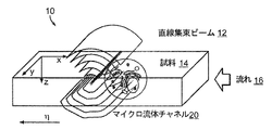
円筒形の収束波(図1A)は、収束線上で同相にある、複数の平面波成分に分解され得る。特に、円筒形レンズで集束された、電場の複素振幅は、次のように、非近軸条件下で記述され得る。

式中、被積分関数は、複素振幅P(λfp)および波ベクトル(p,0,w(p))を備えた平面波を表す。ここで、関数w(p)は、w(p)=((1/λ)2−p2)1/2と定義され、変数λおよびfは、それぞれ照明光の波長および円筒形レンズの焦点距離である。瞳孔関数P(x)は、円筒形レンズの光学収差、または該当する場合はアポディゼーションを表す。定量的位相イメージングでは、瞳孔関数は直接測定され得、複数のイメージから差し引かれ得る。従って、我々は以降の式において、瞳孔関数を省略する。
The cylindrical convergent wave (FIG. 1A) can be decomposed into multiple plane wave components that are homeomorphic on the convergence line. In particular, the complex amplitude of the electric field focused by a cylindrical lens can be described under non-paraxial conditions as follows.
In the equation, the integrand represents a plane wave with complex amplitude P (λfp) and wave vector (p, 0, w (p)). Here, the function w (p) is defined as w (p) = ((1 / λ) 2 −p 2 ) 1/2, and the variables λ and f are the wavelength of the illumination light and the focal length of the cylindrical lens, respectively. The distance. The pupil function P (x) represents the optical aberration of the cylindrical lens, or apodization, if applicable. In quantitative phase imaging, the pupillary function can be measured directly and subtracted from multiple images. Therefore, we omit the pupil function in the following equations.
標本からの散乱場は、入射場のための遠距離場および一般伝送モードで測定されることに留意されたい(図1A)。スカラー回折理論から、散乱場の複素振幅は、次のように記述され得る。
ここで、
here,
関数V(x,y,z)=k2(1-(n(x,y,z)/n0)2) は、標本の散乱ポテンシャルであり、式中、n(x,y,z)およびn0は、それぞれ標本および周囲媒体の屈折率を表す。平面波照明については、式(2)が、従来の光回折断層撮影の複素散乱位相を提供する点に留意されたい。本開示によると、標本を複数の平面波を含む直線集束ビームで照明し、散乱光の複数の角スペクトルを測定する、複数のシステムおよび方法が提供される。断層撮影再構成では、試料が直線集束ビームを通過する間、一連の角スペクトルEsamp(kx,y;η)が試料の様々な位置ηについて記録されてよく、変数kxは空間座標xに対応する空間周波数座標である。光学収差による任意の背景位相を除去すべく、実験を開始する前に、複数の角スペクトルEbg(kx,y)も記録してよい。一次Rytov近似を用い、測定された複数の角スペクトルEsamp(kx,y;η)およびEbg(kx,y)は、標本の散乱ポテンシャルV(x,y,z)に次のように関連付けられ得る。
ここで、
ここで、
式(5)は、測定された、標本からの散乱された複数の角スペクトルを、空間周波数領域内の標本の散乱ポテンシャルにマッピングする方法を提供する。
The function V (x, y, z) = k 2 (1- (n (x, y, z) / n 0 ) 2 ) is the scattering potential of the sample, which is n (x, y, z) in the equation. And n 0 represent the refractive index of the sample and surrounding medium, respectively. Note that for plane wave illumination, equation (2) provides the complex scattering phase of conventional optical diffraction tomography. The present disclosure provides multiple systems and methods for illuminating a sample with a linearly focused beam containing multiple plane waves and measuring multiple angular spectra of scattered light. In a tomographic reconstruction, a series of angular spectra E samp (k x , y; η) may be recorded for various positions η of the sample while the sample passes through the linearly focused beam, where the variable k x is the spatial coordinate x. Spatial frequency coordinates corresponding to. Multiple angular spectra E bg (k x , y) may also be recorded before starting the experiment to eliminate any background phase due to optical aberrations. Using the first-order Rytov approximation, the multiple angular spectra E samp (k x , y; η) and E bg (k x , y) measured give the following to the scattering potential V (x, y, z) of the specimen: Can be associated with.
here,
here,
Equation (5) provides a method of mapping a plurality of measured angular spectra scattered from a sample to the scattering potential of the sample in the spatial frequency domain.
図1Cおよび1Dは、例えば、図1Bに示されるような試料からの複数の角スペクトルを記録するのに使用される例示的なシステム40を示す。このマッハツェンダタイプの干渉計は、ワンショット測定における複素場の振幅と位相の両方の記録を可能にする。当該システムは、例えば、He‐Neレーザ(λ=633nm)の光源42を含んでよい。光源42からのビーム光を拡張すべく、初期ビーム整形オプティクス(例えば、集光レンズのペア)が使用され、その後で、ビーム光は、第1のビームスプリッタB1を使用して、参照ビーム(コリメートされた)および試料ビームにスプリットされる。高開口数の集光レンズ(例えば、開口数=1.4)および円筒形レンズCL(例えば、f=100mm)を使用し、直線集束ビームが試料ビームから生成される。直線集束ビームは、マイクロ流体チャネル20に対し、視野(FOV)平面に焦点が合わされる。従って、システムは、複数の細胞からの複数の角スペクトルを記録しつつ、直線集束ビームを横切って、マイクロ流体チャネル20に複数の細胞の連続的な流れ16を提供する。CMOSカメラ44の特定のフレームレートに対し、約400〜500イメージ/細胞を取得するように、流速は調整され得る(例えば、約15μmの細胞直径を前提とすると、5000フレーム/秒のイメージ取得レートおよび約150μm/秒の流速に対応)。取得された複数のイメージについて、5000フレーム/秒のイメージ取得レートが使用され、それは検出器44での光子束に基づいて判断された。試料に対する高スキャン解像度(例えば、高フレームレート)およびイメージングシステムの高開口数(NA)の両方が、高い空間分解能を実現するのに重要である。しかしながら、スキャン解像度を増大させると、イメージングスループットを低減させ得ることに留意されたい。高NA油浸レンズの作動距離は通常、200μm未満であり、これには上部PDMS(ポリジメチルシロキサン)層の厚みを使用することを含み、複数のマイクロ流体チャネルの全高はそれに応じて小さくなる(例えば、チャネル内部での細胞タンブリングおよび回転を最小化すべく、チャネル高さは複数の細胞の平均直径より僅かに大きくてよい)。ソフトリソグラフィー処理の正確な制御を使用し、これらの基準を満たすマイクロ流体デバイスが作成され、位相イメージングに使用された。取得された複数のイメージについて、使用されたチャネル断面の寸法は、30×400μm2(高さ×幅)であった。いくつかの実施形態において、フローチャネルの中心線と、収集オプティクス近傍の表面との間の基板の厚みは、200μm未満、または好ましくは100μm未満である。
1C and 1D show
複数の例示的な実施形態において、フローチャネルは、例えば、試料の推定された幅サイズの150から200%の間の高さといった、断面直径を含んでよい。いくつかの実施形態において、(i)フローチャネル内の試料の回転を低減する、および(ii)フローチャネル内の試料の安定性を増大させることのうち少なくとも1つのために、フローチャネルの(i)断面高さ、および(ii)断面幅のうち少なくとも1つが、選択されてよい。いくつかの実施形態において、フローチャネルの断面寸法の高さおよび断面寸法の幅は、ほぼ等しくてよい。そのような複数の実施形態においては、回転は本明細書に記載された通り推定されてよい。いくつかの実施形態において、フローチャネルの(i)断面高さ、および(ii)断面幅のうちの少なくとも1つは、例えば、複数のテストされたフローチャネルの各々を流れる参照物質のイメージングから導かれた、複数のテストされたフローチャネルに対する複数の回転推定値等の経験データに基づいて選択されてよい。例えば、そのような回転を補償すべく、試料の推定されたまたは実際の回転に基づいて、回旋が適用されてよい。 In some exemplary embodiments, the flow channel may include a cross-sectional diameter, for example, a height between 150 and 200% of the estimated width size of the sample. In some embodiments, the flow channel (i) is for at least one of (i) reducing the rotation of the sample in the flow channel and (ii) increasing the stability of the sample in the flow channel. At least one of) cross-section height and (ii) cross-section width may be selected. In some embodiments, the height and width of the cross-sectional dimensions of the flow channel may be approximately equal. In such embodiments, the rotation may be estimated as described herein. In some embodiments, at least one of (i) cross-section height and (ii) cross-section width of the flow channel is derived from, for example, imaging of reference material flowing through each of the plurality of tested flow channels. It may be selected based on empirical data such as multiple rotation estimates for multiple tested flow channels. For example, to compensate for such rotation, rotation may be applied based on the estimated or actual rotation of the sample.
イメージデータを処理する、データプロセッサ45が検出器44に接続されている。メモリ47は、電子ディスプレイデバイス49上でユーザーに対し、表示するためのデータを格納できる。プロセッサ45は、システムの複数の作動パラメータを制御するためにも使用され得ることに留意されたい。
A
図1Dは、本発明の好ましい実施形態により、使用されるフローチャネルデバイス50の概略図をさらに示す。適切な3D再構成のため、複数の細胞の高さおよびマイクロ流体チャネル20内のそれらの速度は、それらが直線集束ビームを流れる間、およそ一定であることが要求される。チャネル20は、基板506上に、レンズ(OL)に隣接して配置される実視野54とともに形成される。マニホールド58が、流入ポート60および流出ポート62を通る流体を制御すべく、使用され得る。マイクロ流体チャネルを用いて、水チャネル内の複数のポリスチレンビーズの流れが、照明のためのレーザのような、光源42を備えた高視野顕微鏡を使用して記録された。図1Eは、0.01秒間隔で抽出された、複数の未処理のイメージの合成イメージである。ビーズの変位から、流速は、1mm/秒で均一であると推定され、複数のビーズの流れ方向の直線運動は、横断方向における移動は無視できることを示す。特記すべきことは、インラインホログラフィシステムでは、複数のビーズの高さの変化は、複数の回折リングの変化から認識され得、それはここでは無視できることが示される。
FIG. 1D further shows a schematic diagram of the
図2は、(i)記録された干渉イメージおよび(ii)そのフーリエ変換の振幅の例を示す。点線の円内の領域は、標本からの散乱された角スペクトルの情報を含む。この情報は、軸外デジタルホログラフィによって、非散乱光とは別に記録される(中心がピーク)。点線領域を選択し、点線領域を中心に移動させ、その逆フーリエ変換をすることで、複数の複素角スペクトル
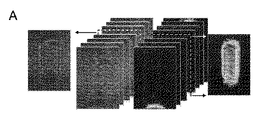
図3A〜図3Cは、空間周波数領域における複数の複素場の例示的マッピングを示す。複数の未処理の干渉イメージ、従って、試料の様々な位置ηに対する複数の角スペクトルが取得され得る(図3A)。次に、kxおよびη方向に沿うデータキューブのフーリエ変換が行われ、それにより図3Bに示すようなサイノグラムを提供する。xおよびyは、空間座標であり、kηは照明角度に対応することに留意されたい。次に、サイノグラムのxとyに対しフーリエ変換を行い、それを3D空間周波数領域に、式(5)のフーリエ回折法則を使用しマッピングする。あるいは、元のデータキューブのxとyに対するフーリエ変換を単純に行い、それを、式(4)を使用して、3D空間周波数領域にマッピングすることができる。 3A-3C show exemplary mappings of multiple complex fields in the spatial frequency domain. Multiple unprocessed interference images, and thus multiple angular spectra for different positions η of the sample, can be obtained (FIG. 3A). Next, a Fourier transform of the data cube along the k x and η directions is performed, thereby providing a synogram as shown in FIG. 3B. Note that x and y are spatial coordinates and k η corresponds to the illumination angle. Next, a Fourier transform is performed on x and y of the synogram, and this is mapped to the 3D spatial frequency region using the Fourier diffraction law of the equation (5). Alternatively, a Fourier transform of the original data cube for x and y can be simply performed and it can be mapped to the 3D spatial frequency domain using equation (4).
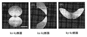
図3Cは、マッピング後のRKOヒト大腸癌細胞の空間周波数マップ
図4Aから4Bは、空間周波数領域における複数の複素場の例示的マッピングを示す。特に、図4Aは、200回反復後の、RKOヒト大腸癌細胞の屈折率マップを示す。図4Aの(i)に、断面中心が細胞の核および核小体を明瞭に示している。図4Aの(ii)は、様々な高さに対して抽出された複数の水平断面図を示す(複数のスライス間の間隔は15μm)。結果は、細胞内の様々な構造を、高度な光学的断面機能を用いて示していることに留意されたい。図4Aの(iii)は、同一細胞の3Dレンダリングイメージによる底部の半分を示す。複数の収集された光学的断面は、メモリに格納され得、複数の別個のスライスまたは領域が表示のために選択され得る。 4A-4B show exemplary mappings of multiple complex fields in the spatial frequency domain. In particular, FIG. 4A shows a refractive index map of RKO human colon cancer cells after 200 iterations. In FIG. 4A (i), the center of the cross section clearly shows the nucleus and nucleolus of the cell. FIG. 4A (ii) shows a plurality of horizontal cross-sectional views extracted for various heights (distance between the plurality of slices is 15 μm). Note that the results show various intracellular structures using advanced optical cross-sectional functions. FIG. 4A (iii) shows the bottom half of the same cell in a 3D rendered image. Multiple collected optical sections may be stored in memory and multiple separate slices or areas may be selected for display.
複数の細胞の質量と体積を測定することは、どのように、複数の細胞が成長し、それらの成長は制御できるのかという、生物学の根本的問題につながる。生物標本の屈折率は、標本内の複数の有機分子の集まりに比例する。この関係を採用すると、細胞内の乾燥密度と呼ばれる、非水物質の密度を次から取得できる。
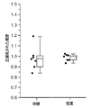
量αは、平均比屈折率インクリメントであり、α=0.18(g/mL)−1である。屈折率マップから、試料の体積は閾値化することで直接的に(例えば、複数のボクセル数を数えることによって)、あるいは球状であることを前提とすると、投影面積から計算可能である。細胞内の合計乾燥質量は、3D密度マップ、式(6)を細胞体積で積分することで取得され得、平均乾燥密度が合計乾燥質量を細胞体積で割り算することで取得される。この方法を検証するために、屈折率1.54の屈折率整合油を流れる、10μmの複数のポリスチレンビーズがイメージされた。当該ポリスチレンビーズ(N=8)の測定された直径は、標準偏差0.35μmの9.89μmであり、屈折率は標準偏差0.005の1.583であった。これらの値は、製造業者によって提供される複数の値(10μm、1.585)と非常によく一致する。製造業者の複数の値で正規化される場合、複数のビーズの体積および屈折率は、それぞれ0.980±0.110および0.986±0.032であり、これらは図4Cに示される。これらの値は、体積および密度の測定に対し、提案される方法の精度に対する複数の推定値として使用されてよい。 The quantity α is the average refractive index increment, and α = 0.18 (g / mL) -1 . From the index of refraction map, the volume of the sample can be calculated directly by thresholding (for example, by counting the number of multiple voxels) or from the projected area, assuming that it is spherical. The total dry mass inside the cell can be obtained by integrating the 3D density map, formula (6) with the cell volume, and the average dry density is obtained by dividing the total dry mass by the cell volume. To verify this method, a plurality of 10 μm polystyrene beads flowing through a refractive index matching oil with a refractive index of 1.54 were imaged. The measured diameter of the polystyrene beads (N = 8) was 9.89 μm with a standard deviation of 0.35 μm, and the refractive index was 1.583 with a standard deviation of 0.005. These values are in very good agreement with the plurality of values (10 μm, 1.585) provided by the manufacturer. When normalized by the manufacturer's values, the volume and index of refraction of the beads are 0.980 ± 0.110 and 0.986 ± 0.032, respectively, which are shown in FIG. 4C. These values may be used as multiple estimates for the accuracy of the proposed method for volume and density measurements.
図4B(i〜iii)は、イメージされた複数のRKOヒト大腸癌細胞(N=60)およびイメージされた複数のRPMI8226ヒト多発性骨髄腫細胞(N=60)の体積、乾燥質量、および乾燥密度をそれぞれ示す。測定が非同調細胞集団に対し適用されたので、質量と体積の分布は広範である。興味深いことに、複数のRPMI8226細胞(1654±69fl)の平均体積は、複数のRKO細胞(1845±70fl)のそれより11.6±6.3%小さい一方で、複数のRPMI8226細胞(345±13pg)の平均乾燥質量は、複数のRKO細胞(300±11pg)のそれより、15.0±5.8%大きい。2つのタイプの細胞の体積は、統計的に異ならないが(p>0.05、両側t検定、N=60)、複数のRPMI8226細胞(170±5g/l)は、それらのより大きい質量に起因し、複数のRKO細胞(145±5g/l)より、17.2±5.4%大きな平均(乾燥)密度を有することに留意されたい。乾燥質量および密度の両方は、2つのタイプの細胞で大きく異なる(p<0.01、両側t検定、N=60)。 FIGS. 4B (i-iii) show the volume, dry mass, and dryness of multiple RKO human colon cancer cells (N = 60) imaged and multiple RPMI8226 human multiple myeloma cells (N = 60) imaged. The densities are shown respectively. The mass and volume distribution is wide, as the measurements were applied to an untuned cell population. Interestingly, the average volume of multiple RPMI8226 cells (1654 ± 69fl) is 11.6 ± 6.3% smaller than that of multiple RKO cells (1845 ± 70fl), while multiple RPMI8226 cells (345 ± 13 pg). ) Is 15.0 ± 5.8% larger than that of multiple RKO cells (300 ± 11 pg). The volumes of the two types of cells are not statistically different (p> 0.05, two-sided t-test, N = 60), but multiple RPMI8226 cells (170 ± 5 g / l) to their larger mass. It should be noted that due to this, it has an average (dry) density 17.2 ± 5.4% greater than multiple RKO cells (145 ± 5 g / l). Both dry mass and density differ significantly between the two types of cells (p <0.01, two-sided t-test, N = 60).
3Dホログラフィックイメージングフローサイトメトリ(3D HIFC)は、マイクロ流体チャネルを連続的に流れる複数の細胞の3D屈折率マップを提供する。特に、複数の試料は、直線集束ビームを横切って流れ、システムは、軸外デジタルホログラフィを使用して、複数の試料から散乱された複数の角スペクトルを記録した。複数の回折および欠損角アーティファクトを適切に処理する再構成アルゴリズムを採用することによって、システムは複数の細胞の3D屈折率マップを高い空間分解能および精度をもって生成する。当該方法は、可動システム要素を何ら要求せず、従って、当該方法は、既存のフローサイトメトリ構成の下流側に容易に組み込まれることができ、さらにスクリーニングの精度を向上させる。より重要なことには、屈折率マップは、細胞または細胞内レベルにおける質量分布に関連付けられ得る豊富な情報を含み、従って、複数の細胞器官のメタボリズムを測定するために使用される。当該システムは、屈折率コントラストを使用することで、汚染のない、精確な、単一の細胞特性評価を提供する。 3D holographic imaging flow cytometry (3D HIFC) provides a 3D index map of multiple cells continuously flowing through a microfluidic channel. In particular, multiple samples flowed across a linearly focused beam, and the system used off-axis digital holography to record multiple angular spectra scattered from the multiple samples. By adopting a reconstruction algorithm that properly handles multiple diffraction and defect angle artifacts, the system produces 3D index maps of multiple cells with high spatial resolution and accuracy. The method does not require any mobile system elements, so the method can be easily incorporated downstream of existing flow cytometry configurations, further improving screening accuracy. More importantly, the index of refraction map contains a wealth of information that can be associated with mass distribution at the cellular or intracellular level and is therefore used to measure the metabolism of multiple organelles. The system uses refractive index contrast to provide a clean, accurate, single cell characterization.
RKOヒト大腸癌細胞は、10%のFBS(インビトロゲン、10438026)および1%の100Xペニシリンストレプトマイシン溶液(インビトロゲン、15140−122)で補足されたダルベッコ変法イーグル培地(インビトロゲン、21063−029)で培養された。複数のRPMI8226ヒト多発性骨髄腫細胞は、10%のFBS、および1%の100Xペニシリンストレプトマイシン溶液で補足されたRPMI 1640培地(インビトロゲン、11835−030)で培養された。70〜80%の密集度で、複数の細胞は0.25%のトリプシンEDTA(インビトロゲン、25200−114)で収集され、新鮮な培地に1:100で希釈され、シリンジでマイクロ流体チャネル内に注入された。複数の10μmのポリスチレンビーズおよび屈折率液体がPolysciences,Inc(17136−5)およびCargille(1809X)からそれぞれ購入された。 RKO human colorectal cancer cells are supplemented with 10% FBS (In vitrogen, 10438026) and 1% 100X penicillin streptomycin solution (In vitrogen, 15140-122) in modified Dulbecco Eagle's medium (In vitrogen, 21063-029). Was cultured in. Multiple RPMI 8226 human multiple myeloma cells were cultured in RPMI 1640 medium (In vitrogen, 11835-030) supplemented with 10% FBS and 1% 100X penicillin streptomycin solution. At 70-80% density, multiple cells were collected with 0.25% trypsin EDTA (In vitrogen, 25200-114), diluted 1: 100 in fresh medium and syringed into a microfluidic channel. Infused. Multiple 10 μm polystyrene beads and refractive index liquids were purchased from Polysciences, Inc (17136-5) and Cargile (1809X), respectively.
マッハツェンダ干渉法に基づく軸外ホログラフィのための、システム40に係る例示的な模式図を示す図1Cおよび1Dに戻ると、例えば、He‐Neレーザ(λ=633nm)のような光源からのレーザビームが、試料ビームおよび参照ビームにスプリットされ(例えば、第1のビームスプリッタB1を使用して)、(例えば、第2のビームスプリッタB2を利用して)検出面の前(検出器44において)で後から結合されている。前述の通り、試料ビームは最初に、円筒形レンズCL(例えば、f=100mm)を用いて、高NA集光レンズL(例えば、NA=1.4)の後焦点面のラインに焦点が合わされている。高NA集光レンズLを使用して、ラインビームは試料平面SP上の細いラインビームにしっかり再度焦点を合わされている。試料平面は元の試料ビームに対し直交してよく、より広い角度範囲を有してよい。複数の試料粒子(例えば、細胞)は、マイクロ流体チャネル内のこのラインビームを横切って流れ、複数の細胞からの散乱光の複数の角スペクトルは、高‐NA対物レンズOLを使用して収集される。集光は、筒型レンズ(TL)を使用して、集束させられ、筒型レンズの後で、ビームは円筒形レンズCL2(例えば、f=400mm)を使用して拡張される。非焦点軸に沿って4f構成にイメージを供給すべく、2つの他の円筒形レンズCL1およびCL3(例えば、f=200mm)がビーム経路に使用されてよい。参照ビームに対し直交するようにビーム軸を変更すべく、ミラーM1が筒型レンズ(TL)および円筒形レンズCL1〜CL3の間に使用されてよく、それにより、第2のビームスプリッタB2を使用して、それらの再結合を可能にする。検出面に入射する角スペクトルの拡大イメージは、参照ビームとともに干渉イメージを作成する。軸外ホログラフィ用に、参照ビームの角度は、例えば、傾斜ミラーM2を使用して、収集された試料ビームに対し僅かに傾斜46されている。円筒形レンズCL2の後焦点面に配置された相補型金属酸化膜半導体(CMOS)カメラ(1024PCI、Photron)は、複数の干渉イメージを例えば、5000フレーム/秒でキャプチャすべく、内部クロックまたは別個のコントローラによって作動され得る。データプロセッサ45は、本明細書に記載の通りデータを処理し、システム動作を制御すべく、コンピュータ可読媒体に格納された複数の命令を実行するソフトウェアを用いてプログラムされ得る。複数の例示的な実施形態において、集光レンズLおよび/または対物レンズOLは、0.5より大きい、好ましくは1.0より大きい、より好ましくは1.3より大きい、高開口数によって特徴付けられてよい。
Returning to FIGS. 1C and 1D showing exemplary schematics of the
特に、軸外ホログラフィを使用すると、流れる試料の各位置に対しワンショットで、角スペクトルの振幅と位相の両方を記録することが可能になる。従って、複数の例示的な実施形態において、試料ビームに対する参照ビームの僅かな傾斜は、複数の未処理の干渉イメージにおける3ピクセルフリンジ周期を生じさせるべく構成される。例示的な実施形態において、検出された参照光および検出された散乱光の間の角度オフセットは、2.5〜4ピクセル間の未処理の干渉イメージにおけるフリンジ周期によって特徴付けられる。 In particular, off-axis holography makes it possible to record both the amplitude and phase of the angular spectrum in one shot for each position of the flowing sample. Thus, in a plurality of exemplary embodiments, a slight tilt of the reference beam with respect to the sample beam is configured to produce a 3-pixel fringe period in the plurality of unprocessed coherent images. In an exemplary embodiment, the angular offset between the detected reference light and the detected scattered light is characterized by a fringe period in the unprocessed interference image between 2.5-4 pixels.
複数の例示的な実施形態において、検出システムは、試料ごとに少なくとも30イメージ、好ましくは試料ごとに少なくとも100イメージ、より好ましくは試料ごとに少なくとも200イメージのスキャン解像度を使用してよい。いくつかの実施形態において、検出された角度範囲は、少なくとも−30度から30度、好ましくは少なくとも−45度から45度、より好ましくは少なくとも−60度から60度であってよい。従って、検出された角度分解能は、少なくとも2度、またはより好ましくは少なくとも1度であってよい。 In a plurality of exemplary embodiments, the detection system may use a scan resolution of at least 30 images per sample, preferably at least 100 images per sample, more preferably at least 200 images per sample. In some embodiments, the detected angular range may be at least −30 ° to 30 °, preferably at least −45 ° to 45 °, and more preferably at least −60 ° to 60 °. Therefore, the detected angular resolution may be at least 2 degrees, or more preferably at least 1 degree.
3次元の屈折率測定は、最小摂動で細胞全体および複数の内部の細胞器官の質量を測定することによって、細胞メタボリズムを定量化することを可能にする。平面波の断層撮影を使用することで、付着力のある状態で成長する複数の細胞は、複数の浮遊細胞のように、サイズ別の成長速度を有する一方で、分裂非対称は前者の方がより高いことが実証された。低ノイズ回折位相差顕微鏡と連携し、哺乳類の軟骨細胞は、体積増加に関する3つの異なる段階を受けることが本明細書において、さらに実証され、また示される。最近の結果は、多波長における屈折率測定から、複数の細胞の分子固有の指標が取得され得ることを示す。 Three-dimensional refractive index measurement makes it possible to quantify cell metabolism by measuring the mass of the entire cell and multiple internal organelles with minimal perturbations. By using plane-wave tomography, multiple cells that grow in a cohesive state, like multiple floating cells, have growth rates by size, while mitotic asymmetry is higher in the former. It was proved that. In conjunction with a low noise diffraction phase contrast microscope, it is further demonstrated and shown herein that mammalian chondrocytes undergo three different stages of volume gain. Recent results show that molecular-specific indicators of multiple cells can be obtained from refractive index measurements at multiple wavelengths.
本明細書に示されるように、マイクロ流体チャネル内を連続的に流れる複数の細胞の屈折率イメージングのための複数のシステムおよび方法が提供される。特に、記載された複数のシステムおよび方法は、流れる試料の各位置に対し、ワンショットで複素角スペクトルを測定可能な軸外デジタルホログラフィを使用する。断層撮影再構成のために、スカラー回折理論に基づくアルゴリズムが採用され、異なる複数の高さを流れる焦点がぼけた複数の細胞器官または細胞に起因する複数のアーティファクトが修正されてよい。これらの複数の技術を使用すると、フロー構成における異なる複数のタイプの細胞に関する屈折率の複数の3Dマッピングを取得でき、それによって、複数の細胞の体積、乾燥質量および乾燥密度のような複数の特性を定量化できる。これは、フロー構成で細胞密度を取得するための複数の先行技術に対し、複数の顕著な利点を与える。先行技術は、2つの異なる密度の液体に対し、懸濁されたマイクロチャネル共振器を使用する、浮遊質量測定に依存する。その場合、各測定に対し、当該液体を切り替えることは、健全な、自然な状態における複数の細胞の高スループットまたは長期のイメージングに対し理想的ではないことがある。 As shown herein, multiple systems and methods are provided for refractive index imaging of multiple cells flowing continuously within a microfluidic channel. In particular, the described systems and methods use off-axis digital holography capable of measuring a complex angle spectrum in one shot for each position of a flowing sample. For tomography reconstruction, algorithms based on scalar diffraction theory may be employed to correct multiple defocused organelles or artifacts resulting from cells flowing at different heights. Using these multiple techniques, multiple 3D mappings of refractive index for different types of cells in the flow configuration can be obtained, thereby allowing multiple properties such as volume, dry mass and dry density of multiple cells. Can be quantified. This provides several significant advantages over multiple prior arts for obtaining cell density in flow configurations. Prior art relies on stray mass measurements using suspended microchannel resonators for two different densities of liquid. In that case, switching the liquid for each measurement may not be ideal for high throughput or long-term imaging of multiple cells in a healthy, natural state.
本明細書から導かれ、採用される断層撮影再構成アルゴリズムは、チャネル内の細胞の鉛直位置は固定されており、かつ、データ収集の間、または各セルの直線集束ビームを横切って完全に通過する間に対し、細胞の回転は無視できることを前提とする。コリメートされたレーザ照明の下、高速カメラを用いて、複数の細胞を観察すると、細胞タンブリングは、本明細書に記載の設計条件およびフロー条件に対し最小であることが確認され得る。しかしながら、マイクロ流体チャネル内を流れる複数の細胞を安定化させるメカニズムを用いずに、細胞の回転の可能性は、完全に除外され得ない。複数のマイクロ流体システムにおいて、細胞の回転は、フロー速度に比例し、細胞のサイズに反比例する、細胞に働くせん断力によって引き起こされる。細胞がチャネルの高さの真ん中に位置する際、細胞の複数の側面における流体速度の差が減少するので、チャネルの高さの半分より大きい細胞は、このせん断力によってあまり影響を受けない。複数の空気欠陥とともに複数のPDMSビーズをイメージングすることにより、データ取得中(0.1秒)における、複数の細胞(平均直径:〜15μm)の最大回転は、約5×10−3のレイノルズ数において、約4度であると推定できる。この回転の最小効果は、図4Aの、複数の再構成された例示イメージ内の細胞と核の複数のはっきりした境界によってさらに確認される。回転していれば、おそらくぼやけを生じさせたことであろう。 The tomography reconstruction algorithms derived and adopted herein have fixed vertical positions of cells within a channel and pass completely during data acquisition or across the linearly focused beam of each cell. It is assumed that the rotation of cells can be ignored while doing so. Observation of multiple cells using a high-speed camera under collimated laser illumination can confirm that cell tumbling is minimal for the design and flow conditions described herein. However, the possibility of cell rotation cannot be completely ruled out without a mechanism that stabilizes multiple cells flowing through the microfluidic channel. In multiple microfluidic systems, cell rotation is caused by shear forces acting on cells that are proportional to flow velocity and inversely proportional to cell size. Cells greater than half the channel height are less affected by this shear force, as the difference in fluid velocities on multiple sides of the cell is reduced when the cell is located in the middle of the channel height. By imaging multiple PDMS beads with multiple air defects, the maximum rotation of multiple cells (mean diameter: ~ 15 μm) during data acquisition (0.1 sec) is approximately 5 × 10 -3 Reynolds number. In, it can be estimated to be about 4 degrees. The minimal effect of this rotation is further confirmed by the multiple clear boundaries of cells and nuclei within the multiple reconstructed exemplary images of FIG. 4A. If it was spinning, it would probably have caused blurring.
好ましい実施形態において、屈折率分散を測定すべく、チャネル内を流れる物質を照明するため、複数の異なる波長の光が使用され得る。断層イメージングに対する複数の波長の使用に関するさらなる詳細は、Sung他のPLOSONE、Vol、7、11(2012)の「Stain−Free Quantification of Chromosomes in Live Cells Using Regularized Tomographic Phase Microscopy」に見出され得、その全内容は参照により本明細書に組み込まれる。従って、試料の複数のイメージが、異なる複数の照明波長において取得され得る。 In a preferred embodiment, a plurality of different wavelengths of light may be used to illuminate the material flowing through the channel in order to measure the index of refraction dispersion. Further details regarding the use of multiple wavelengths for tomographic imaging can be found in Sung et al., PLOS ONE, Vol. 7, 11 (2012), "Stain-Free Quantification of Chromosomes in Live Cells in Live Cells, Regularized, Tomography", and Tomography. The entire contents are incorporated herein by reference. Therefore, multiple images of the sample can be acquired at different different illumination wavelengths.
各角スペクトルの振幅と位相は、上記の軸外ホログラフィセットアップによって記録される。図2の(i〜iv)は、未処理の干渉イメージの処理方法を示す。検出器上の放射照度は、次のように表され得る。
ここで、Is(x,y)およびIRは、それぞれ試料ビームおよび参照ビームの放射照度であり、Δφ(x,y)は、当該2つのビームの間の位相差である。ベクトル(p,q)は、参照ビームの角度に対する、検出面上の試料ビームの入射角を示す。ベクトルの大きさおよび角度は、未処理の干渉における、複数のフリンジ(図2の(i)の挿絵を参照)の間隔および向きをそれぞれ示す。図2の(ii)は、図2の(i)のフーリエ変換の大きさ、または対数尺度(底10)の式(7)を示す。点線の円内の領域は、次によって記述され得る。
ここで、
Here, I s (x, y) and I R are the irradiance of each sample and reference beams, [Delta] [phi (x, y) is the phase difference between the two beams. The vector (p, q) indicates the angle of incidence of the sample beam on the detection plane with respect to the angle of the reference beam. The magnitude and angle of the vector indicate the spacing and orientation of the plurality of fringes (see illustration in FIG. 2 (i)) in unprocessed interference, respectively. FIG. 2 (ii) shows the magnitude of the Fourier transform of FIG. 2 (i) or the equation (7) of the logarithmic scale (base 10). The area within the dotted circle can be described by:
here,
複数のマイクロ流体デバイスは、微細加工されたマスタモールドで、ポリジメチルシロキサン(ミシガン州ミッドランドのダウコーニングのPDMS)を成型することによって生成された。モールドは、後述される複数の標準的なフォトリソグラフィックテクノロジを使用して製造された。シリコンウェハが200℃にセットされたオーブンで30分間焼成され、酸素プラズマ(カリフォルニア州コンコルドのMarch)で洗浄され、その後、およそ30μmの最終厚みを実現すべく、1850rpmでSU−8 25フォトレジスト(マサチューセッツ州ニュートンのMicrochemのSU8)で回転塗布され、製造業者によって推奨される、標準的な手順に従い処理された。PDMSの薄膜層(厚み<200μm)が作成され、真空チャンバで約1時間ガス抜きされ、その後、600rpmで、ウェハ上に15秒間回転塗布された。65℃で約8時間焼成後、より厚い、硬化されたカット済みの複数のPDMSピース(長さ〜1cm、幅〜0.5cm、高さ〜0.3cm)とともに、マスタを覆うPDMS薄膜層は、酸素プラズマに20秒間さらされ、入口領域および出口領域(図1E)に接着された。モールドは、75℃で10分間焼成され、切断され、マスタモールドからゆっくり剥離され、その後、デバイスの入口穴と出口穴を画定すべく、0.75mmパンチャで穿孔された。最後に、穿孔されたメンブレンベースのチャネルデバイスとともに、48×65mmのNo.1金被覆カバーガラス(ペンシルバニア州ピッツバーグのFisher Scientific)が酸素プラズマに20秒間さらされ、複数のマイクロ流体チャネルを画定すべく、注意深く75℃において10分間接着された。可撓性のあるプラスチック管の2つが、〜3cmの長さに切断され(マサチューセッツ州ウーバンのGreene Rubber Co.,社のタイゴン、ID0.010インチ×OD0.030インチ)、その後、デバイスの入口穴と出口穴に挿入された。次に、複数の試料装填の目的のため、シリンジが接続されるのを可能にすべく、30gの鈍化針(ニュージャージー州デイトンのBrico Medical Supplies)が当該2つの管の一方に挿入された。もう一方の流体試料ソースは、システムと共に使用するため、流入ポートに接続され得る。イメージされた試料を、流出ポートから収集すべく、試料収集コンテナが使用され得る。 Multiple microfluidic devices were produced by molding polydimethylsiloxane (Dow Corning PDMS, Midland, Michigan) in a microfabricated master mold. Molds were manufactured using several standard photolithographic technologies described below. Silicon wafers are fired in an oven set at 200 ° C. for 30 minutes, washed with oxygen plasma (March, Concorde, CA), and then SU-825 photoresists (1850 rpm) to achieve a final thickness of approximately 30 μm. Rotum application was performed at Microchem SU8) in Newton, Massachusetts, and processed according to standard procedures recommended by the manufacturer. A thin film layer of PDMS (thickness <200 μm) was prepared, degassed in a vacuum chamber for about 1 hour, then spun on the wafer at 600 rpm for 15 seconds. After firing at 65 ° C. for about 8 hours, the PDMS thin film layer covering the master, along with a number of thicker, hardened, pre-cut PDMS pieces (length ~ 1 cm, width ~ 0.5 cm, height ~ 0.3 cm) , Exposed to oxygen plasma for 20 seconds and adhered to the inlet and outlet regions (FIG. 1E). The mold was fired at 75 ° C. for 10 minutes, cut, slowly stripped from the master mold, and then perforated with a 0.75 mm puncher to demarcate the inlet and outlet holes of the device. Finally, with a perforated membrane-based channel device, a 48 x 65 mm No. A 1-karat gold coated cover glass (Fisher Scientific, Pittsburgh, PA) was exposed to oxygen plasma for 20 seconds and carefully adhered at 75 ° C. for 10 minutes to define multiple microfluidic channels. Two flexible plastic tubes were cut to a length of ~ 3 cm (Greene Hubber Co., Woburn, Massachusetts, Tygon, ID 0.010 inch x OD 0.030 inch), followed by a device inlet hole. Was inserted into the exit hole. A 30 g blunting needle (Brico Medical Supplies, Dayton, NJ) was then inserted into one of the two tubes to allow the syringes to be connected for multiple sample loading purposes. The other fluid sample source can be connected to the inflow port for use with the system. A sample collection container may be used to collect the imaged sample from the outflow port.
図5に示されるのは、本発明の複数の好ましい実施形態によるプロセス順序100である。そこでは、データプロセッサ45が、イメージング検出器からイメージデータを受信し、フローチャネル内のシステムの実視野を移動する試料に係る複数の2次元および3次元イメージを生成すべく、イメージデータを処理し、試料の屈折率の3次元分布を決定する。データプロセッサが以下の一連の命令を実行するように、ソフトウェアプログラムがメモリ内に格納され得る。オブジェクトの複数の3次元イメージを生成すべく、一連の干渉イメージが検出される102。各未処理のイメージからの位相データおよび振幅データが抽出され104、さらなる処理のためにメモリ内に格納され得る。複数の抽出された場は、3Dサイノグラム106にマッピングされ得、そこにおけるηは様々な座標である。サイノグラムのx-y平面に対するフーリエ変換が計算され108、その結果が周波数領域の散乱ポテンシャルにマッピングされる110。本明細書に記載の通り、反復的な再構成処理が適用され112、逆フーリエ変換が使用され114、計算された屈折率分布116を生成する。
Shown in FIG. 5 is a
本発明の複数の好ましい実施形態は、試料に関する補足情報を生成すべく、多様なイメージング機能を使用できる。これは、測定される物質をさらに特性化すべく、追加の複数の分析処理も提供できる。図6Aは、前述の通り、複数の干渉イメージが、異なる複数の角度202から取得される、プロセスフロー順序200を示す。フーリエマッピング204後、測定される物質の形態をより正確に反射すべく、平滑化制約206がデータに適用され得る。例えば、細胞物質は通常、中心に、より均一な屈折率分布を有し、細胞の境界において急な推移を受ける。対象の複数の細胞が、チャネル内を流れる周囲媒体よりも、より高い屈折率を有することを示し得る、正制約も使用されてよい。複数の試料エラーに起因して発生し得る周波数空間の空の領域に入力すべく210、追加のデータも使用され得る。収束212が測定され得、必要に応じて所望の収束値を実現すべく、複数の制約ステップが反復214され得るよう、この正規化処理は反復プロセス順序の一部として使用され得る。
A plurality of preferred embodiments of the present invention can use a variety of imaging functions to generate supplemental information about the sample. It can also provide multiple analytical processes to further characterize the material being measured. FIG. 6A shows a
図6Bのプロセス順序250に見られるように、複数の好ましい実施形態は、異なる複数の特性を決定すべく254、チャネル内の複数の開口または領域を介する測定252を提供し得る。本明細書に全般的に記載される干渉イメージングに加え、測定中、フロー内の複数の細胞が回転しているかどうか、回転速度を判断し、かつ、回転速度を修正すべく角度試料数を増大させる等、複数のイメージングパラメータを調整するために使用され得る、複数の補正信号を生成すべく、第2の領域における複数の測定のために、第2の検出器が使用され得る。あるいは、結果的に得られるイメージデータが、より低い角度サンプリング処理のために、修正され得るよう、試料の全体積をイメージすべく、試料からの光を反射する第2のレーザ光源を使用する共焦点イメージングが使用され得る。この方法を使用して、試料の蛍光は測定され得る。別のオプションは、第2の波長における複数のイメージ、および物質の異なる複数の構造的または組成的特性を検出すべく比較される複数のイメージを生成する。このデータは、本明細書に記載された複数の反復技術を使用して、分析され得る256。データは、さらなる処理または表示のために格納され得る258。
As seen in
本発明は、複数の特定の好ましい実施形態に関連して本明細書において記載されており、当業者は本出願を読んだ後、本明細書に記載された複数のデバイスおよび方法に対し、複数の変更、複数の均等物による複数の置換、他の変形をもたらすことができる。本明細書に記載された各実施形態は、他の複数の実施形態とともに開示された、そのような変更を含むこともできる。
本明細書によれば、以下の各項目に記載の構成もまた開示される。
[項目1]
軸外ホログラフィのためのイメージングシステムであって、
試料ビーム経路と、参照ビーム経路と、に分割される光を放出する照明源と、
検出において、検出された参照光は、検出された散乱光に対して角度オフセットするように、前記試料ビーム経路に沿って収集された前記散乱光と、前記参照ビーム経路に沿って前記参照光と、の両方を検出する検出システムと、を備え、
前記試料ビーム経路は、
試料を直線集束ビームで照明すべく、前記試料ビーム経路に沿って、前記光の焦点を合わせる試料照明オプティクスと、
前記試料ビーム経路に沿って、試料から散乱された光を収集する収集オプティクスと、を含んでいる、イメージングシステム。
[項目2]
前記照明源は、コリメートされた照明源である、請求項1に記載のシステム。
[項目3]
前記照明源は、多波長の照明源である、請求項1に記載のシステム。
[項目4]
前記照明源から放出される前記光を、前記試料ビーム経路と、前記参照ビーム経路とに分割するためのスプリッタをさらに備える、請求項1に記載のシステム。
[項目5]
前記参照ビーム経路は、検出された前記参照光を、検出された前記散乱光に対して角度オフセットする、オフセットオプティクスを含む、請求項1に記載のシステム。
[項目6]
前記オフセットオプティクスは、傾斜ミラーを含む、請求項5に記載のシステム。
[項目7]
前記試料および前記直線集束ビームを互いに相対的に並進させる、スキャンシステムをさらに備える、請求項1に記載のシステム。
[項目8]
前記スキャンシステムは、前記試料を、前記直線集束ビームを横断して並進させる、請求項7に記載のシステム。
[項目9]
前記スキャンシステムは、懸濁培地に懸濁された試料を、直線集束ビームを横断して流す、基板で定義されたフローチャネルを含む、請求項8に記載のシステム。
[項目10]
前記試料は細胞である、請求項9に記載のシステム。
[項目11]
前記フローチャネルは、前記試料の推定された幅サイズの150〜200%の間の断面直径を含む、請求項9に記載のシステム。
[項目12]
前記断面直径は、前記フローチャネルの断面高さである、請求項11に記載のシステム。
[項目13]
(i)前記フローチャネル内の前記試料の回転を低減させる、および(ii)前記フローチャネル内の前記試料の安定性を増大させることのうち少なくとも1つのために、前記フローチャネルの(i)断面高さ、および(ii)断面幅のうち少なくとも1つが、選択される、請求項9に記載のシステム。
[項目14]
前記フローチャネルの前記断面高さは、前記フローチャネルの前記断面幅とほぼ同じであり、前記フローチャネルの前記断面高さおよび前記断面幅を選択すべく、前記フローチャネルの前記断面高さおよび前記断面幅に基づく回転推定値が使用される、請求項13に記載のシステム。
[項目15]
前記フローチャネルの(i)前記断面高さおよび(ii)前記断面幅のうち少なくとも1つが、経験データに基づいて選択される、請求項13に記載のシステム。
[項目16]
前記経験データは、複数のテストされたフローチャネルの各々の中を流れる参照物質のイメージングに基づいて、複数のテストされたフローチャネルに対する複数の回転推定値を含む、請求項15に記載のシステム。
[項目17]
前記フローチャネルの中心線と、前記収集オプティクス近傍の表面との間の前記基板の厚みは、200μm未満である、請求項9に記載のシステム。
[項目18]
前記フローチャネルの中心線と、前記収集オプティクス近傍の表面との間の前記基板の厚みは、100μm未満である、請求項9に記載のシステム。
[項目19]
当該システムはマルチモードシステムである、請求項1に記載のシステム。
[項目20]
前記マルチモードシステムは、前記試料の推定されたまたは実際の試料の回転を検出する、回転検出システムを含む、請求項19に記載のシステム。
[項目21]
前記マルチモードシステムは、共焦点顕微鏡システムを含む、請求項19に記載のシステム。
[項目22]
前記共焦点顕微鏡システムは、前記試料のための複数の体積の測定を検出する、請求項21に記載のシステム。
[項目23]
前記マルチモードシステムは、それぞれが異なる波長範囲のための複数のイメージングシステムを含む、請求項19に記載のシステム。
[項目24]
前記マルチモードシステムは、それぞれがフローチャネル沿いの異なるポイントにおける、複数の開口を含む、請求項19に記載のシステム。
[項目25]
前記マルチモードシステムは、共有された開口を含む、請求項19に記載のシステム。
[項目26]
検出された前記参照光と、検出された前記散乱光との間の前記角度オフセットは、検出された前記参照光のビーム軸と、検出された前記散乱光のビーム軸との間の角度オフセットである、請求項1に記載のシステム。
[項目27]
検出された前記参照光と、検出された前記散乱光との間の前記角度オフセットは、2.5〜4ピクセルの間の、複数の未処理の干渉イメージにおけるフリンジ周期によって特徴付けられる、請求項1に記載のシステム。
[項目28]
前記試料照明オプティクスは、円筒形レンズおよび集光レンズを含み、
前記円筒形レンズは、照明経路沿いの光の焦点を、前記集光レンズの後焦点面の線に合わせ、
前記集光レンズは、前記線の焦点を試料平面上に再度合わせる、請求項1に記載のシステム。
[項目29]
前記集光レンズは、高開口数のレンズである、請求項28に記載のシステム。
[項目30]
前記集光レンズは、0.5より多い開口数を含む、請求項29に記載のシステム。
[項目31]
前記集光レンズは、1.0より多い開口数を含む、請求項29に記載のシステム。
[項目32]
前記集光レンズは、1.3より多い開口数を含む、請求項29に記載のシステム。
[項目33]
前記収集オプティクスは、高開口数対物レンズを含む、請求項1に記載のシステム。
[項目34]
前記対物レンズは、0.5より多い開口数を含む、請求項33に記載のシステム。
[項目35]
前記対物レンズは、1.0より多い開口数を含む、請求項33に記載のシステム。
[項目36]
前記対物レンズは、1.3より多い開口数を含む、請求項33に記載のシステム。
[項目37]
前記収集オプティクスはさらに、前記対物レンズの下流側に、収集された前記散乱光の焦点を合わせるための管形レンズを含む、請求項33に記載のシステム。
[項目38]
前記収集オプティクスはさらに、前記管形レンズの下流側に、円筒形レンズを含む、請求項37に記載のシステム。
[項目39]
前記収集オプティクスはさらに、前記管形レンズの下流側に、非焦点軸に沿い4f構成を実装するための、一連の円筒形レンズを含む、請求項37に記載のシステム。
[項目40]
検出された前記散乱光は、前記試料から散乱された複数の角スペクトルを含む、請求項1に記載のシステム。
[項目41]
前記検出システムは、試料ごとに少なくとも30イメージのスキャン解像度を使用する、請求項1に記載のシステム。
[項目42]
前記検出システムは、試料ごとに少なくとも100イメージのスキャン解像度を使用する、請求項1に記載のシステム。
[項目43]
前記検出システムは、試料ごとに少なくとも200イメージのスキャン解像度を使用する、請求項1に記載のシステム。
[項目44]
少なくとも−30度から30度の検出された角度範囲で特徴付けられる、請求項1に記載のシステム。
[項目45]
少なくとも−45度から45度の検出された角度範囲で特徴付けられる、請求項1に記載のシステム。
[項目46]
少なくとも−60度から60度の検出された角度範囲で特徴付けられる、請求項1に記載のシステム。
[項目47]
少なくとも2度の検出された角解像度で特徴付けられる、請求項1に記載のシステム。
[項目48]
少なくとも1度の検出された角解像度で特徴付けられる、請求項1に記載のシステム。
[項目49]
前記試料の様々な位置ηに対する複数の角スペクトルを含む、複数の未処理の干渉イメージを取得すべく、検出された前記参照光と、検出された前記散乱光とが使用される、請求項1に記載のシステム。
[項目50]
前記検出システムは、kx(空間座標xに対応する空間周波数)方向およびη方向に沿って、フーリエ変換を計算してそれにより、サイノグラムを提供し、さらに前記サイノグラムのx空間座標とy空間座標に対するフーリエ変換を計算し、それを、フーリエ回折定理を使用して、3D空間周波数領域にマッピングする、請求項49に記載のシステム。
[項目51]
前記検出システムは、データプロセッサに接続される、請求項1に記載のシステム。
[項目52]
フローサイトメトリの方法であって、
試料を、チャネルを通して移動させる段階と、
前記チャネル内で、移動する前記試料を収束光で照明する段階と、
照明光に応答して、前記試料からの光を検出する段階と、
前記試料のイメージを形成する段階と、を備える、方法。
[項目53]
前記試料の複数の位相イメージを生成する段階をさらに備える、請求項52に記載の方法。
[項目54]
前記チャネルを横断して延びる線上の前記チャネルを照明する段階をさらに備える、請求項52に記載の方法。
[項目55]
イメージデータをデータプロセッサで処理する段階をさらに備える、請求項52に記載の方法。
[項目56]
前記試料の3次元(3D)イメージを生成する段階をさらに備える、請求項52に記載の方法。
[項目57]
前記試料は、生物物質を含む、請求項52に記載の方法。
[項目58]
前記試料は、生物流体を含む、請求項52に記載の方法。
[項目59]
前記試料は、細胞を含む、請求項52に記載の方法。
[項目60]
前記試料は、癌性細胞を含む、請求項52に記載の方法。
[項目61]
前記試料の屈折率を決定する段階をさらに備える、請求項52に記載の方法。
[項目62]
前記試料のイメージを電子ディスプレイ上に表示する段階をさらに備える、請求項52に記載の方法。
[項目63]
制御システムを前記試料上で光をスキャンする複数のスキャンパラメータでプログラミングする段階をさらに備える、請求項52に記載の方法。
[項目64]
収束円筒形光学要素で、光の焦点を前記チャネル上に合わせる、請求項52に記載の方法。
[項目65]
前記チャネル内の流体の流速を調整する段階をさらに備える、請求項52に記載の方法。
[項目66]
前記試料の干渉イメージを生成する段階をさらに備える、請求項52に記載の方法。
[項目67]
前記イメージからの位相データを生成する段階をさらに備える、請求項52から66のいずれか一項に記載の方法。
[項目68]
前記イメージからの振幅データを生成する段階をさらに備える、請求項52から67のいずれか一項に記載の方法。
[項目69]
位相データおよび振幅データを3次元表示にマッピングする段階をさらに備える、請求項52から68のいずれか一項に記載の方法。
[項目70]
3次元表示は、サイノグラムである、請求項52に記載の方法。
[項目71]
マッピングされたデータの2次元フーリエ変換を形成する段階をさらに備える、請求項52から70のいずれか一項に記載の方法。
[項目72]
フーリエ変化された角スペクトルを、空間周波数領域内の前記試料の散乱ポテンシャルにマッピングする段階をさらに備える、請求項71に記載の方法。
[項目73]
計算された散乱ポテンシャルを提供すべく、反復計算を実行する段階をさらに備える、請求項72に記載の方法。
[項目74]
3次元散乱ポテンシャルを決定すべく、逆フーリエ変換を実行する段階をさらに備える、請求項71から73のいずれか一項に記載の方法。
[項目75]
前記試料の屈折率を決定する段階をさらに備える、請求項52から74のいずれか一項に記載の方法。
[項目76]
前記試料の屈折率分布を決定する段階をさらに備える、請求項52から75のいずれか一項に記載の方法。
[項目77]
照明光を前記チャネルの視野に供給する段階をさらに備える、請求項52から76のいずれか一項に記載の方法。
[項目78]
検出器において、参照光ビーム経路を、試料光ビーム経路に対し傾斜させる段階をさらに備える、請求項52から77のいずれか一項に記載の方法。
[項目79]
前記参照光ビーム経路および前記試料光ビーム経路は、ゼロより大きい角度で傾斜されている、請求項78に記載の方法。
[項目80]
検出器で干渉パターンを検出する段階をさらに備える、請求項52から79のいずれか一項に記載の方法。
[項目81]
供給オプティクスで、光源からの光を前記試料に連結する段階をさらに備える、請求項52から80のいずれか一項に記載の方法。
[項目82]
収集オプティクスで、前記試料からの光を検出器に連結する段階をさらに備える、請求項52から81のいずれか一項に記載の方法。
[項目83]
照明ビームを作動された光学素子に移動する段階をさらに備える、請求項52から82のいずれか一項に記載の方法。
[項目84]
前記作動された光学素子は、可動ミラーを含む、請求項83に記載の方法。
[項目85]
前記作動された光学素子は、スキャナを含む、請求項83に記載の方法。
[項目86]
イメージデータを平滑化制約で処理する段階をさらに備える、請求項52に記載の方法。
[項目87]
イメージデータを正制約で処理する段階をさらに備える、請求項52に記載の方法。
[項目88]
周波数空間の領域に入力するデータを生成する段階をさらに備える、請求項52に記載の方法。
[項目89]
前記試料を第1の波長および第2の波長で照明する段階をさらに備える、請求項52に記載の方法。
[項目90]
データを正規化する段階をさらに備える、請求項52に記載の方法。
[項目91]
前記チャネル内の前記試料の領域の回転を測定する段階をさらに備える、請求項52に記載の方法。
[項目92]
前記チャネル内の前記試料の共焦点イメージを取得する段階をさらに備える、請求項52に記載の方法。
[項目93]
前記試料内の蛍光を検出する段階をさらに備える、請求項52に記載の方法。
The present invention has been described herein in the context of a plurality of specific preferred embodiments, and those skilled in the art will, after reading the present application, a plurality of devices and methods described herein. Changes, multiple substitutions with multiple equivalents, and other variants can be brought about. Each embodiment described herein may also include such modifications disclosed with a plurality of other embodiments.
According to the present specification, the configurations described in the following items are also disclosed.
[Item 1]
An imaging system for off-axis holography
An illumination source that emits light divided into a sample beam path and a reference beam path,
In the detection, the detected reference light includes the scattered light collected along the sample beam path and the reference light along the reference beam path so as to be angularly offset with respect to the detected scattered light. With a detection system that detects both,
The sample beam path is
Sample illumination optics that focus the light along the sample beam path to illuminate the sample with a linearly focused beam.
An imaging system comprising a collection optic that collects light scattered from a sample along the sample beam path.
[Item 2]
The system according to
[Item 3]
The system according to
[Item 4]
The system of
[Item 5]
The system of
[Item 6]
The system of
[Item 7]
The system of
[Item 8]
The system of claim 7, wherein the scanning system translates the sample across the linear focused beam.
[Item 9]
The system of claim 8, wherein the scan system comprises a substrate-defined flow channel that allows a sample suspended in a suspension medium to flow across a linearly focused beam.
[Item 10]
The system of claim 9, wherein the sample is a cell.
[Item 11]
The system of claim 9, wherein the flow channel comprises a cross-sectional diameter between 150 and 200% of the estimated width size of the sample.
[Item 12]
The system according to claim 11, wherein the cross-sectional diameter is the cross-sectional height of the flow channel.
[Item 13]
(I) Cross section of the flow channel for at least one of (i) reducing rotation of the sample in the flow channel and (ii) increasing stability of the sample in the flow channel. 9. The system of claim 9, wherein at least one of the height and (ii) cross-sectional width is selected.
[Item 14]
The cross-sectional height of the flow channel is substantially the same as the cross-sectional width of the flow channel, and the cross-sectional height of the flow channel and the cross-sectional height of the flow channel are selected in order to select the cross-sectional height and the cross-sectional width of the flow channel. 13. The system of claim 13, wherein rotation estimates based on cross-sectional width are used.
[Item 15]
13. The system of claim 13, wherein at least one of (i) the cross-sectional height and (ii) the cross-sectional width of the flow channel is selected based on empirical data.
[Item 16]
The system of claim 15, wherein the empirical data comprises a plurality of rotation estimates for the plurality of tested flow channels based on imaging of reference material flowing through each of the plurality of tested flow channels.
[Item 17]
9. The system of claim 9, wherein the thickness of the substrate between the centerline of the flow channel and the surface in the vicinity of the collection optics is less than 200 μm.
[Item 18]
9. The system of claim 9, wherein the thickness of the substrate between the centerline of the flow channel and the surface in the vicinity of the collection optics is less than 100 μm.
[Item 19]
The system according to
[Item 20]
19. The system of claim 19, wherein the multimode system includes a rotation detection system that detects the estimated or actual rotation of the sample.
[Item 21]
19. The system of claim 19, wherein the multimode system includes a confocal microscope system.
[Item 22]
21. The system of claim 21, wherein the confocal microscope system detects a plurality of volume measurements for the sample.
[Item 23]
19. The system of claim 19, wherein the multimode system comprises a plurality of imaging systems, each of which has a different wavelength range.
[Item 24]
19. The system of claim 19, wherein the multimode system comprises a plurality of openings, each at a different point along a flow channel.
[Item 25]
19. The system of claim 19, wherein the multimode system includes a shared aperture.
[Item 26]
The angular offset between the detected reference light and the detected scattered light is the angular offset between the detected beam axis of the reference light and the detected beam axis of the scattered light. The system according to
[Item 27]
Claim that the angular offset between the detected reference light and the detected scattered light is characterized by a fringe period in a plurality of unprocessed interference images between 2.5 and 4 pixels. The system according to 1.
[Item 28]
The sample illumination optics include a cylindrical lens and a condenser lens.
The cylindrical lens focuses light along the illumination path to the line of the posterior focal plane of the condenser lens.
The system of
[Item 29]
28. The system of claim 28, wherein the condenser lens is a lens with a high numerical aperture.
[Item 30]
29. The system of claim 29, wherein the condenser lens comprises a numerical aperture greater than 0.5.
[Item 31]
29. The system of claim 29, wherein the condenser lens comprises a numerical aperture greater than 1.0.
[Item 32]
29. The system of claim 29, wherein the condenser lens comprises a numerical aperture greater than 1.3.
[Item 33]
The system of
[Item 34]
33. The system of claim 33, wherein the objective lens comprises a numerical aperture greater than 0.5.
[Item 35]
33. The system of claim 33, wherein the objective lens comprises a numerical aperture greater than 1.0.
[Item 36]
33. The system of claim 33, wherein the objective lens comprises a numerical aperture greater than 1.3.
[Item 37]
33. The system of claim 33, wherein the acquisition optics further comprises a tubular lens for focusing the collected scattered light downstream of the objective lens.
[Item 38]
37. The system of claim 37, wherein the collection optics further comprises a cylindrical lens downstream of the tubular lens.
[Item 39]
37. The system of claim 37, wherein the collection optics further comprises a series of cylindrical lenses for mounting a 4f configuration along a nonfocal axis downstream of the tubular lens.
[Item 40]
The system according to
[Item 41]
The system of
[Item 42]
The system of
[Item 43]
The system of
[Item 44]
The system of
[Item 45]
The system of
[Item 46]
The system of
[Item 47]
The system of
[Item 48]
The system of
[Item 49]
1. The detected reference light and the detected scattered light are used in order to obtain a plurality of unprocessed interference images including a plurality of angular spectra for various position ηs of the sample. The system described in.
[Item 50]
The detection system calculates a Fourier transform along the k x (spatial frequency corresponding to the spatial coordinate x) direction and the η direction, thereby providing a synogram, and further, the x space coordinate and the y space coordinate of the synogram. 49. The system of
[Item 51]
The system according to
[Item 52]
It ’s a flow cytometry method,
The step of moving the sample through the channel and
A step of illuminating the moving sample with focused light in the channel,
The stage of detecting the light from the sample in response to the illumination light, and
A method comprising: forming an image of the sample.
[Item 53]
52. The method of claim 52, further comprising generating a plurality of phase images of the sample.
[Item 54]
52. The method of claim 52, further comprising illuminating the channel on a line extending across the channel.
[Item 55]
52. The method of claim 52, further comprising processing the image data with a data processor.
[Item 56]
52. The method of claim 52, further comprising generating a three-dimensional (3D) image of the sample.
[Item 57]
52. The method of claim 52, wherein the sample comprises a biological material.
[Item 58]
52. The method of claim 52, wherein the sample comprises a biofluid.
[Item 59]
52. The method of claim 52, wherein the sample comprises cells.
[Item 60]
52. The method of claim 52, wherein the sample comprises cancerous cells.
[Item 61]
52. The method of claim 52, further comprising the step of determining the refractive index of the sample.
[Item 62]
52. The method of claim 52, further comprising displaying an image of the sample on an electronic display.
[Item 63]
52. The method of claim 52, further comprising programming the control system with a plurality of scan parameters that scan light on the sample.
[Item 64]
52. The method of claim 52, wherein the focused cylindrical optical element focuses light on the channel.
[Item 65]
52. The method of claim 52, further comprising adjusting the flow rate of the fluid in the channel.
[Item 66]
52. The method of claim 52, further comprising generating an interference image of the sample.
[Item 67]
The method according to any one of claims 52 to 66, further comprising a step of generating phase data from the image.
[Item 68]
The method according to any one of claims 52 to 67, further comprising a step of generating amplitude data from the image.
[Item 69]
The method according to any one of claims 52 to 68, further comprising a step of mapping phase data and amplitude data to a three-dimensional display.
[Item 70]
The method of claim 52, wherein the three-dimensional display is a synogram.
[Item 71]
The method according to any one of claims 52 to 70, further comprising the step of forming a two-dimensional Fourier transform of the mapped data.
[Item 72]
17. The method of claim 71, further comprising mapping the Fourier transformed angular spectrum to the scattering potential of the sample in the spatial frequency domain.
[Item 73]
72. The method of claim 72, further comprising performing iterative calculations to provide the calculated scattering potential.
[Item 74]
The method of any one of claims 71-73, further comprising performing an inverse Fourier transform to determine the three-dimensional scattering potential.
[Item 75]
The method according to any one of claims 52 to 74, further comprising a step of determining the refractive index of the sample.
[Item 76]
The method according to any one of claims 52 to 75, further comprising a step of determining the refractive index distribution of the sample.
[Item 77]
The method according to any one of claims 52 to 76, further comprising a step of supplying illumination light to the field of view of the channel.
[Item 78]
The method according to any one of claims 52 to 77, further comprising a step of inclining the reference light beam path with respect to the sample light beam path in the detector.
[Item 79]
The method of claim 78, wherein the reference light beam path and the sample light beam path are tilted at an angle greater than zero.
[Item 80]
The method according to any one of claims 52 to 79, further comprising a step of detecting an interference pattern with a detector.
[Item 81]
The method of any one of claims 52-80, further comprising connecting light from a light source to the sample in feed optics.
[Item 82]
The method of any one of claims 52-81, further comprising connecting light from the sample to a detector in the collection optics.
[Item 83]
The method of any one of claims 52-82, further comprising moving the illumination beam to the actuated optics.
[Item 84]
The method of claim 83, wherein the actuated optical element comprises a movable mirror.
[Item 85]
The method of claim 83, wherein the activated optical element comprises a scanner.
[Item 86]
52. The method of claim 52, further comprising processing the image data with a smoothing constraint.
[Item 87]
52. The method of claim 52, further comprising processing the image data with positive constraints.
[Item 88]
52. The method of claim 52, further comprising generating data to be input into a region of frequency space.
[Item 89]
52. The method of claim 52, further comprising illuminating the sample with a first wavelength and a second wavelength.
[Item 90]
52. The method of claim 52, further comprising a step of normalizing the data.
[Item 91]
52. The method of claim 52, further comprising measuring the rotation of a region of the sample within the channel.
[Item 92]
52. The method of claim 52, further comprising obtaining a confocal image of the sample in the channel.
[Item 93]
52. The method of claim 52, further comprising a step of detecting fluorescence in the sample.
Claims (27)
試料ビーム経路と、参照ビーム経路と、に分割される光を放出する照明源と、
検出において、検出された参照光は、検出された散乱光に対して角度オフセットして試料の角スペクトルが生成されるように、前記試料ビーム経路に沿って収集された前記散乱光と、前記参照ビーム経路に沿って収集された前記参照光と、の両方を検出する検出システムと、
前記検出システムに接続されるデータプロセッサと、を備え、
前記試料ビーム経路は、
前記試料を直線集束ビームで照明すべく、前記試料ビーム経路に沿って、前記光の焦点を合わせる照明オプティクスと、
懸濁培地に懸濁された細胞を含む試料を、前記直線集束ビームを横断して連続して流す基板で画定されたフローチャネルであり、前記フローチャネルは、前記試料ビーム経路内の前記細胞の回転を抑制する大きさを有する、フローチャネルと、
前記試料ビーム経路に沿って、試料から散乱された光を収集する収集オプティクスと、を含み、
前記データプロセッサは、検出された前記参照光と検出された前記散乱光とを使用して、前記フローチャネル内の前記試料の様々な位置ηに対する干渉イメージを取得し、前記干渉イメージを処理して前記角スペクトルの位相データおよび振幅データを3次元表示にマッピングし、前記マッピングされたデータを2次元フーリエ変換することができ、処理された前記角スペクトルを空間周波数領域内の前記試料の散乱ポテンシャルにさらにマッピングすることができる、イメージングシステム。 An imaging system for off-axis holography
An illumination source that emits light divided into a sample beam path and a reference beam path,
In the detection, the detected reference light is the scattered light collected along the sample beam path and the reference so that the angular spectrum of the sample is generated at an angle offset with respect to the detected scattered light. A detection system that detects both the reference light collected along the beam path, and
With a data processor connected to the detection system ,
The sample beam path is
Illumination optics that focus the light along the sample beam path to illuminate the sample with a linearly focused beam.
A flow channel defined by a substrate that continuously flows a sample containing cells suspended in a suspension medium across the linear focused beam, wherein the flow channel is a flow channel of the cells in the sample beam path. A flow channel with a size that suppresses rotation,
Includes collection optics, which collect light scattered from the sample along the sample beam path.
The data processor uses the detected to have been detected the reference beam the scattered light to obtain interference images to various locations η of the sample in the flow in the channel, and processing the interference image maps phase data and amplitude data of the angle spectrum in 3-dimensional Display, the mapped data may be two-dimensional Fourier transform, and the angle spectrum which is processed in said sample the spatial frequency region An imaging system that can be further mapped to the scattering potential.
前記参照ビーム経路は、検出された前記参照光を検出された前記散乱光に対して角度オフセットする傾斜ミラーを含むオフセットオプティックスを含む、請求項1または2に記載のイメージングシステム。 Further comprising a splitter for splitting the light emitted from the illumination source into the sample beam path and the reference beam path.
The imaging system according to claim 1 or 2, wherein the reference beam path includes offset optics including a tilted mirror that angularly offsets the detected reference light with respect to the detected scattered light.
前記細胞は、生分解性である、請求項1から3のいずれか一項に記載のイメージングシステム。 Further comprising a scanning system for translating the sample and the linearly focused beam relative to each other or a scanning system for translating the sample across the linearly focused beam.
The imaging system according to any one of claims 1 to 3, wherein the cells are biodegradable.
任意で、前記フローチャネルの前記断面高さは、前記フローチャネルの前記断面幅とほぼ同じであり、前記フローチャネルの前記断面高さおよび前記断面幅を選択すべく、前記フローチャネルの前記断面高さおよび前記断面幅に基づく回転推定値が使用される、請求項5に記載のイメージングシステム。 (I) Cross section of the flow channel for at least one of (i) reducing rotation of the sample in the flow channel and (ii) increasing stability of the sample in the flow channel. At least one of the height and (ii) cross-sectional width is selected.
Optionally, the cross-sectional height of the flow channel is approximately the same as the cross-sectional width of the flow channel, and the cross-sectional height of the flow channel is selected to select the cross-sectional height and the cross-sectional width of the flow channel. The imaging system according to claim 5, wherein a rotation estimate based on the cross-sectional width is used.
前記経験データは、複数のテストされたフローチャネルの各々の中を流れる参照物質のイメージングに基づいて、複数のテストされた前記フローチャネルに対する複数の回転推定値を含む、請求項5または6に記載のイメージングシステム。 At least one of (i) cross-section height and (ii) cross-section width of the flow channel is selected based on empirical data.
The empirical data according to claim 5 or 6, wherein the empirical data comprises a plurality of rotation estimates for the plurality of tested flow channels based on imaging of a reference material flowing through each of the plurality of tested flow channels. Imaging system.
前記円筒形レンズは、照明経路沿いの光の焦点を、前記集光レンズの後焦点面の線に合わせ、
前記集光レンズは、前記線の焦点を試料平面上に再度合わせる、請求項1から11のいずれか一項に記載のイメージングシステム。 The illumination optics include a cylindrical lens and a condenser lens.
The cylindrical lens focuses light along the illumination path to the line of the posterior focal plane of the condenser lens.
The imaging system according to any one of claims 1 to 11, wherein the condenser lens refocuses the line on a sample plane.
試料を、基板のチャネルを通して移動させる段階であり、前記チャネルは前記試料の回転を抑制する大きさを有する、段階と、
前記チャネル内で、移動する前記試料を収束光で照明する段階と、
検出器を用いて、前記試料からの散乱光及び前記試料からの前記散乱光から角度オフセットされた参照光を検出する段階であり、前記試料からの前記散乱光及び前記参照光は光源からの照明光に応答する、段階と、
検出された前記参照光と検出された前記散乱光とを使用して、前記チャネル内の前記試料の様々な位置ηに対する干渉イメージを形成する段階と、
前記干渉イメージを処理して角スペクトルの位相データおよび振幅データを3次元表示にマッピングし、前記マッピングされたデータを2次元フーリエ変換し、処理された前記角スペクトルを空間周波数空間内の前記試料の散乱ポテンシャルにマッピングする段階と、
を備える、方法。 A method of flow cytometry using an off-axis holography system,
A step in which the sample is moved through a channel of the substrate, and the channel has a size that suppresses the rotation of the sample.
A step of illuminating the moving sample with focused light in the channel,
Using a detector, a said step of detecting the reference light angle offset from the scattered light from the scattered light and the sample from the sample, the scattered light and the reference light from the sample is illuminated from a light source In response to light, stages and
Test out the in use and said reference light and said detected scattered light, forming an interference image of various locations η of the sample in said channel,
The interference image by processing the maps phase data and amplitude data of the angular spectrum in a three-dimensional display, the data mapped two-dimensional Fourier transform, the sample in the angle spectrum which is processed spatial frequency space And the stage of mapping to the scattering potential of
A method.
前記試料は、生物流体または細胞を含む生物物質を含む、請求項19または20に記載の方法。 Further provided with a step of generating a three-dimensional (3D) image of the sample.
The method of claim 19 or 20, wherein the sample comprises a biofluid or a biological material comprising cells.
Priority Applications (1)
| Application Number | Priority Date | Filing Date | Title |
|---|---|---|---|
| JP2019040963A JP6958964B2 (en) | 2013-02-05 | 2019-03-06 | 3D holographic imaging flow cytometry |
Applications Claiming Priority (3)
| Application Number | Priority Date | Filing Date | Title |
|---|---|---|---|
| US201361761079P | 2013-02-05 | 2013-02-05 | |
| US61/761,079 | 2013-02-05 | ||
| PCT/US2014/014955 WO2014124057A1 (en) | 2013-02-05 | 2014-02-05 | 3-d holographic imaging flow cytometry |
Related Child Applications (1)
| Application Number | Title | Priority Date | Filing Date |
|---|---|---|---|
| JP2019040963A Division JP6958964B2 (en) | 2013-02-05 | 2019-03-06 | 3D holographic imaging flow cytometry |
Publications (3)
| Publication Number | Publication Date |
|---|---|
| JP2016511435A JP2016511435A (en) | 2016-04-14 |
| JP2016511435A5 JP2016511435A5 (en) | 2017-03-09 |
| JP6801846B2 true JP6801846B2 (en) | 2020-12-16 |
Family
ID=50156932
Family Applications (2)
| Application Number | Title | Priority Date | Filing Date |
|---|---|---|---|
| JP2015556256A Active JP6801846B2 (en) | 2013-02-05 | 2014-02-05 | 3D holographic imaging flow cytometry |
| JP2019040963A Active JP6958964B2 (en) | 2013-02-05 | 2019-03-06 | 3D holographic imaging flow cytometry |
Family Applications After (1)
| Application Number | Title | Priority Date | Filing Date |
|---|---|---|---|
| JP2019040963A Active JP6958964B2 (en) | 2013-02-05 | 2019-03-06 | 3D holographic imaging flow cytometry |
Country Status (4)
| Country | Link |
|---|---|
| US (1) | US10670510B2 (en) |
| EP (1) | EP2954309B1 (en) |
| JP (2) | JP6801846B2 (en) |
| WO (1) | WO2014124057A1 (en) |
Families Citing this family (55)
| Publication number | Priority date | Publication date | Assignee | Title |
|---|---|---|---|---|
| WO2014079478A1 (en) | 2012-11-20 | 2014-05-30 | Light In Light Srl | High speed laser processing of transparent materials |
| EP2754524B1 (en) * | 2013-01-15 | 2015-11-25 | Corning Laser Technologies GmbH | Method of and apparatus for laser based processing of flat substrates being wafer or glass element using a laser beam line |
| EP2781296B1 (en) | 2013-03-21 | 2020-10-21 | Corning Laser Technologies GmbH | Device and method for cutting out contours from flat substrates using a laser |
| US9676167B2 (en) | 2013-12-17 | 2017-06-13 | Corning Incorporated | Laser processing of sapphire substrate and related applications |
| US10293436B2 (en) | 2013-12-17 | 2019-05-21 | Corning Incorporated | Method for rapid laser drilling of holes in glass and products made therefrom |
| US9850160B2 (en) | 2013-12-17 | 2017-12-26 | Corning Incorporated | Laser cutting of display glass compositions |
| US10442719B2 (en) | 2013-12-17 | 2019-10-15 | Corning Incorporated | Edge chamfering methods |
| US11556039B2 (en) | 2013-12-17 | 2023-01-17 | Corning Incorporated | Electrochromic coated glass articles and methods for laser processing the same |
| US9815730B2 (en) | 2013-12-17 | 2017-11-14 | Corning Incorporated | Processing 3D shaped transparent brittle substrate |
| US9701563B2 (en) | 2013-12-17 | 2017-07-11 | Corning Incorporated | Laser cut composite glass article and method of cutting |
| US20150165560A1 (en) | 2013-12-17 | 2015-06-18 | Corning Incorporated | Laser processing of slots and holes |
| TWI730945B (en) | 2014-07-08 | 2021-06-21 | 美商康寧公司 | Methods and apparatuses for laser processing materials |
| CN107073641B (en) | 2014-07-14 | 2020-11-10 | 康宁股份有限公司 | Interface blocks; systems and methods for dicing substrates transparent in the wavelength range using such interface blocks |
| WO2016010949A1 (en) | 2014-07-14 | 2016-01-21 | Corning Incorporated | Method and system for forming perforations |
| EP3169479B1 (en) | 2014-07-14 | 2019-10-02 | Corning Incorporated | Method of and system for arresting incident crack propagation in a transparent material |
| KR20170028943A (en) * | 2014-07-14 | 2017-03-14 | 코닝 인코포레이티드 | System for and method of processing transparent materials using laser beam focal lines adjustable in length and diameter |
| US10047001B2 (en) | 2014-12-04 | 2018-08-14 | Corning Incorporated | Glass cutting systems and methods using non-diffracting laser beams |
| FR3030749B1 (en) * | 2014-12-19 | 2020-01-03 | Commissariat A L'energie Atomique Et Aux Energies Alternatives | METHOD OF IDENTIFYING BIOLOGICAL PARTICLES BY STACKS OF DEFOCALIZED HOLOGRAPHIC IMAGES |
| CN107406293A (en) | 2015-01-12 | 2017-11-28 | 康宁股份有限公司 | The substrate through heat tempering is cut by laser using Multiphoton Absorbtion method |
| US11773004B2 (en) | 2015-03-24 | 2023-10-03 | Corning Incorporated | Laser cutting and processing of display glass compositions |
| KR20170131638A (en) | 2015-03-27 | 2017-11-29 | 코닝 인코포레이티드 | Gas Permeable Glass Window and Method of Making the Same |
| WO2017011296A1 (en) | 2015-07-10 | 2017-01-19 | Corning Incorporated | Methods of continuous fabrication of holes in flexible substrate sheets and products relating to the same |
| EP3220130B1 (en) * | 2016-03-16 | 2023-03-01 | Siemens Healthcare GmbH | High accuracy 5-part differential with digital holographic microscopy and untouched leukocytes from peripheral blood |
| WO2017192896A1 (en) | 2016-05-06 | 2017-11-09 | Uwm Research Foundation, Inc. | Snapshot optical tomography system and method of acquiring an image with the system |
| JP6938543B2 (en) | 2016-05-06 | 2021-09-22 | コーニング インコーポレイテッド | Laser cutting and removal of contoured shapes from transparent substrates |
| US10410883B2 (en) | 2016-06-01 | 2019-09-10 | Corning Incorporated | Articles and methods of forming vias in substrates |
| KR101865624B1 (en) | 2016-06-10 | 2018-06-11 | 주식회사 토모큐브 | 3D Refractive Index Tomogram and Structured Illumination Microscopy System using Wavefront Shaper and Method thereof |
| US10794679B2 (en) | 2016-06-29 | 2020-10-06 | Corning Incorporated | Method and system for measuring geometric parameters of through holes |
| KR20190035805A (en) | 2016-07-29 | 2019-04-03 | 코닝 인코포레이티드 | Apparatus and method for laser processing |
| KR102423775B1 (en) | 2016-08-30 | 2022-07-22 | 코닝 인코포레이티드 | Laser processing of transparent materials |
| US10730783B2 (en) | 2016-09-30 | 2020-08-04 | Corning Incorporated | Apparatuses and methods for laser processing transparent workpieces using non-axisymmetric beam spots |
| KR102428350B1 (en) | 2016-10-24 | 2022-08-02 | 코닝 인코포레이티드 | Substrate processing station for laser-based machining of sheet-like glass substrates |
| US10752534B2 (en) | 2016-11-01 | 2020-08-25 | Corning Incorporated | Apparatuses and methods for laser processing laminate workpiece stacks |
| US10688599B2 (en) | 2017-02-09 | 2020-06-23 | Corning Incorporated | Apparatus and methods for laser processing transparent workpieces using phase shifted focal lines |
| US10983209B2 (en) * | 2017-04-12 | 2021-04-20 | Ellumen, Inc. | Accurate signal compensations for UWB radar imaging in dispersive medium |
| US10580725B2 (en) | 2017-05-25 | 2020-03-03 | Corning Incorporated | Articles having vias with geometry attributes and methods for fabricating the same |
| US11078112B2 (en) | 2017-05-25 | 2021-08-03 | Corning Incorporated | Silica-containing substrates with vias having an axially variable sidewall taper and methods for forming the same |
| EP3413033B1 (en) | 2017-06-09 | 2020-09-23 | Roche Diagnostics GmbH | Method and apparatus for determining properties of a laboratory sample contained in a laboratory sample container |
| US10626040B2 (en) | 2017-06-15 | 2020-04-21 | Corning Incorporated | Articles capable of individual singulation |
| CN110799829B (en) * | 2017-07-06 | 2023-01-03 | 特拉维夫大学拉莫特有限公司 | System and method for three-dimensional label-free optical imaging of biological cell samples in environmental chambers |
| CN107271421A (en) * | 2017-07-27 | 2017-10-20 | 深圳中科芯海智能科技有限公司 | A kind of microparticle fluorescence detection means in fluid sample |
| TW201919805A (en) * | 2017-08-25 | 2019-06-01 | 美商康寧公司 | Apparatuses and methods for laser processing transparent workpieces using an afocal beam adjustment assembly |
| EP3462170B1 (en) | 2017-09-29 | 2020-09-16 | Siemens Healthcare GmbH | Specific malaria detection with digital optical microscopy |
| WO2019076938A1 (en) * | 2017-10-16 | 2019-04-25 | Scherr Steven | Systems and methods for particulate encapsulation in microdroplets |
| US12180108B2 (en) | 2017-12-19 | 2024-12-31 | Corning Incorporated | Methods for etching vias in glass-based articles employing positive charge organic molecules |
| US11554984B2 (en) | 2018-02-22 | 2023-01-17 | Corning Incorporated | Alkali-free borosilicate glasses with low post-HF etch roughness |
| WO2020014858A1 (en) * | 2018-07-17 | 2020-01-23 | 深圳大学 | Fiber mach-zehnder interferometer-based biosensor and production method therefor |
| JP7026853B2 (en) | 2019-06-28 | 2022-02-28 | 富士フイルム株式会社 | Image processing equipment, evaluation system, image processing program and image processing method |
| WO2021240512A1 (en) * | 2020-05-25 | 2021-12-02 | Ramot At Tel-Aviv University Ltd. | A tomography system and a method for analysis of biological cells |
| JP7495301B2 (en) | 2020-08-28 | 2024-06-04 | 浜松ホトニクス株式会社 | Learning model generation method, classification method, learning model generation system, classification system, learning model generation program, classification program, and recording medium |
| RU2770567C1 (en) * | 2021-06-26 | 2022-04-18 | федеральное государственное бюджетное образовательное учреждение высшего образования «Донской государственный технический университет», (ДГТУ) | Method for holographic analysis of suspended particles |
| JP2024022034A (en) * | 2022-08-05 | 2024-02-16 | 浜松ホトニクス株式会社 | A method for determining a region of a cell that has undergone programmed cell death, an apparatus including a determination unit, and an information processing program including a determination step |
| CN116540212A (en) * | 2023-07-06 | 2023-08-04 | 中国空气动力研究与发展中心超高速空气动力研究所 | Three-dimensional imaging device and method |
| WO2025168660A1 (en) * | 2024-02-06 | 2025-08-14 | Leibniz-Institut Für Naturstoff-Forschung Und Infektionsbiologie E. V. - Hans-Knöll-Institut (Hki) | Optical measuring device, measurement method and evaluation method |
| CN119470168B (en) * | 2024-11-04 | 2025-07-25 | 上海健康医学院 | Method, device and equipment for evaluating interaction between nano preparation and cells |
Family Cites Families (15)
| Publication number | Priority date | Publication date | Assignee | Title |
|---|---|---|---|---|
| US4293221A (en) | 1979-04-17 | 1981-10-06 | Research Corporation | Multidimensional slit-scan flow system |
| US5633714A (en) | 1994-12-19 | 1997-05-27 | International Business Machines Corporation | Preprocessing of image amplitude and phase data for CD and OL measurement |
| US6744038B2 (en) | 2000-11-13 | 2004-06-01 | Genoptix, Inc. | Methods of separating particles using an optical gradient |
| WO2002059584A2 (en) * | 2000-12-29 | 2002-08-01 | Chromagen, Inc. | Scanning spectrophotometer for high throughput fluorescence detection |
| US7365858B2 (en) | 2001-12-18 | 2008-04-29 | Massachusetts Institute Of Technology | Systems and methods for phase measurements |
| DE10254139A1 (en) | 2002-11-15 | 2004-05-27 | Carl Zeiss Jena Gmbh | Method and arrangement for the depth-resolved optical detection of a sample |
| WO2006010253A1 (en) | 2004-07-30 | 2006-02-02 | University Of Victoria Innovation And Development Corporation | Confocal scanning holography microscope |
| EP1864112B1 (en) | 2005-03-25 | 2015-05-06 | Massachusetts Institute of Technology | Device and method for hilbert phase imaging |
| TW200706831A (en) | 2005-08-08 | 2007-02-16 | Zetetic Inst | Apparatus and methods for reduction and compensation of effects of vibrations and of environmental effects in wavefront interferometry |
| EP2010885B1 (en) | 2006-04-07 | 2020-06-03 | Ecole Polytechnique Fédérale de Lausanne | Method and apparatus to measure and compute the amplitude point spread function and associated parameters of a coherent optical imaging system |
| US7633631B2 (en) | 2007-04-04 | 2009-12-15 | Nikon Corporation | Three-dimensional microscope and method for obtaining three-dimensional image |
| US8848199B2 (en) * | 2007-07-10 | 2014-09-30 | Massachusetts Institute Of Technology | Tomographic phase microscopy |
| CN102439416B (en) | 2009-03-20 | 2015-11-25 | 伯乐实验室有限公司 | Serial Line-Scan Coded Multicolor Fluorescence Microscopy and Imaging Flow Cytometry |
| CN103238120B (en) * | 2010-11-12 | 2016-08-10 | 布鲁塞尔大学 | For characterizing the optical means of transparent grain |
| US8896840B2 (en) | 2012-04-25 | 2014-11-25 | Canon Kabushiki Kaisha | Interferometric method and digital holographic microscope |
-
2014
- 2014-02-05 JP JP2015556256A patent/JP6801846B2/en active Active
- 2014-02-05 EP EP14706193.1A patent/EP2954309B1/en active Active
- 2014-02-05 US US14/173,804 patent/US10670510B2/en active Active
- 2014-02-05 WO PCT/US2014/014955 patent/WO2014124057A1/en not_active Ceased
-
2019
- 2019-03-06 JP JP2019040963A patent/JP6958964B2/en active Active
Also Published As
| Publication number | Publication date |
|---|---|
| US20140333929A1 (en) | 2014-11-13 |
| EP2954309A1 (en) | 2015-12-16 |
| WO2014124057A1 (en) | 2014-08-14 |
| JP2019148798A (en) | 2019-09-05 |
| JP2016511435A (en) | 2016-04-14 |
| EP2954309B1 (en) | 2019-08-28 |
| US10670510B2 (en) | 2020-06-02 |
| JP6958964B2 (en) | 2021-11-02 |
Similar Documents
| Publication | Publication Date | Title |
|---|---|---|
| JP6958964B2 (en) | 3D holographic imaging flow cytometry | |
| Nguyen et al. | Quantitative phase imaging: recent advances and expanding potential in biomedicine | |
| US11125686B2 (en) | System and method for three-dimensional label-free optical imaging of a biological cell sample in an environmental chamber | |
| Sung et al. | Three-dimensional holographic refractive-index measurement of continuously flowing cells in a microfluidic channel | |
| US10113961B2 (en) | Apparatus and method for quantitive phase tomography through linear scanning with coherent and non-coherent detection | |
| US9546952B2 (en) | Distribution of refractive index measurement by synthetic aperture tomography | |
| JP6130464B2 (en) | System and method for Hilbert phase image processing | |
| Baffou | Wavefront microscopy using quadriwave lateral shearing interferometry: from bioimaging to nanophotonics | |
| KR101855366B1 (en) | Method and system for 3d label-free imaging and quantification of lipid doplets in live hepatocytes | |
| CN116337811B (en) | Optical diffraction tomography microscopy method based on opposite illumination | |
| Cairós et al. | Refractive index estimation in biological tissues by quantitative phase imaging | |
| Desissaire et al. | Bio-inspired 3d-printed phantom: Encoding cellular heterogeneity for characterization of quantitative phase imaging | |
| JP7275849B2 (en) | Method and apparatus for measuring cell number, morphology or shape | |
| Pavillon et al. | Implementation of simultaneous quantitative phase with Raman imaging | |
| Popescu | The power of imaging with phase, not power | |
| JP7228189B2 (en) | Method and apparatus for evaluating cytotoxicity | |
| US20070171433A1 (en) | Systems and processes for providing endogenous molecular imaging with mid-infrared light | |
| CN104517319A (en) | BOSVS (Bergman operator splitting algorithm with variable stepsize)-based three-dimensional fault phase microscope reconstruction method | |
| US20230351648A1 (en) | A tomography system and a method for analysis of biological cells | |
| Levin et al. | An automated interference microscope for measuring dynamic objects | |
| Min et al. | Optical diffraction tomographic microscopy: a cutting-edge label-free three-dimensional bioimaging | |
| Shipp | Holographic angular domain elastic scattering of single biological cells | |
| Kujawińska et al. | Tailor-made 3D-printed phantoms for metrology of quantitative phase imaging systems in biomedical applications | |
| Hua et al. | Chemosensitivity testing of revived fresh-frozen biopsies using digital speckle holography | |
| Zvahelskyi | On In-situ Imaging for 3D Laser Microprinting |
Legal Events
| Date | Code | Title | Description |
|---|---|---|---|
| A521 | Request for written amendment filed |
Free format text: JAPANESE INTERMEDIATE CODE: A523 Effective date: 20170202 |
|
| A621 | Written request for application examination |
Free format text: JAPANESE INTERMEDIATE CODE: A621 Effective date: 20170202 |
|
| A977 | Report on retrieval |
Free format text: JAPANESE INTERMEDIATE CODE: A971007 Effective date: 20171025 |
|
| A131 | Notification of reasons for refusal |
Free format text: JAPANESE INTERMEDIATE CODE: A131 Effective date: 20171128 |
|
| A601 | Written request for extension of time |
Free format text: JAPANESE INTERMEDIATE CODE: A601 Effective date: 20180227 |
|
| A601 | Written request for extension of time |
Free format text: JAPANESE INTERMEDIATE CODE: A601 Effective date: 20180427 |
|
| A521 | Request for written amendment filed |
Free format text: JAPANESE INTERMEDIATE CODE: A523 Effective date: 20180528 |
|
| A02 | Decision of refusal |
Free format text: JAPANESE INTERMEDIATE CODE: A02 Effective date: 20181106 |
|
| A521 | Request for written amendment filed |
Free format text: JAPANESE INTERMEDIATE CODE: A523 Effective date: 20190306 |
|
| C60 | Trial request (containing other claim documents, opposition documents) |
Free format text: JAPANESE INTERMEDIATE CODE: C60 Effective date: 20190306 |
|
| A521 | Request for written amendment filed |
Free format text: JAPANESE INTERMEDIATE CODE: A821 Effective date: 20190308 |
|
| A911 | Transfer to examiner for re-examination before appeal (zenchi) |
Free format text: JAPANESE INTERMEDIATE CODE: A911 Effective date: 20190327 |
|
| C21 | Notice of transfer of a case for reconsideration by examiners before appeal proceedings |
Free format text: JAPANESE INTERMEDIATE CODE: C21 Effective date: 20190402 |
|
| A912 | Re-examination (zenchi) completed and case transferred to appeal board |
Free format text: JAPANESE INTERMEDIATE CODE: A912 Effective date: 20190607 |
|
| C211 | Notice of termination of reconsideration by examiners before appeal proceedings |
Free format text: JAPANESE INTERMEDIATE CODE: C211 Effective date: 20190611 |
|
| C22 | Notice of designation (change) of administrative judge |
Free format text: JAPANESE INTERMEDIATE CODE: C22 Effective date: 20191112 |
|
| C22 | Notice of designation (change) of administrative judge |
Free format text: JAPANESE INTERMEDIATE CODE: C22 Effective date: 20200121 |
|
| C13 | Notice of reasons for refusal |
Free format text: JAPANESE INTERMEDIATE CODE: C13 Effective date: 20200303 |
|
| A601 | Written request for extension of time |
Free format text: JAPANESE INTERMEDIATE CODE: A601 Effective date: 20200528 |
|
| A601 | Written request for extension of time |
Free format text: JAPANESE INTERMEDIATE CODE: A601 Effective date: 20200731 |
|
| A521 | Request for written amendment filed |
Free format text: JAPANESE INTERMEDIATE CODE: A523 Effective date: 20200901 |
|
| C23 | Notice of termination of proceedings |
Free format text: JAPANESE INTERMEDIATE CODE: C23 Effective date: 20200923 |
|
| C03 | Trial/appeal decision taken |
Free format text: JAPANESE INTERMEDIATE CODE: C03 Effective date: 20201027 |
|
| C30A | Notification sent |
Free format text: JAPANESE INTERMEDIATE CODE: C3012 Effective date: 20201027 |
|
| A61 | First payment of annual fees (during grant procedure) |
Free format text: JAPANESE INTERMEDIATE CODE: A61 Effective date: 20201117 |
|
| R150 | Certificate of patent or registration of utility model |
Ref document number: 6801846 Country of ref document: JP Free format text: JAPANESE INTERMEDIATE CODE: R150 |
|
| R250 | Receipt of annual fees |
Free format text: JAPANESE INTERMEDIATE CODE: R250 |
|
| R250 | Receipt of annual fees |
Free format text: JAPANESE INTERMEDIATE CODE: R250 |
|
| R250 | Receipt of annual fees |
Free format text: JAPANESE INTERMEDIATE CODE: R250 |