JP6802007B2 - Shielding structure for inward doors - Google Patents
Shielding structure for inward doors Download PDFInfo
- Publication number
- JP6802007B2 JP6802007B2 JP2016162703A JP2016162703A JP6802007B2 JP 6802007 B2 JP6802007 B2 JP 6802007B2 JP 2016162703 A JP2016162703 A JP 2016162703A JP 2016162703 A JP2016162703 A JP 2016162703A JP 6802007 B2 JP6802007 B2 JP 6802007B2
- Authority
- JP
- Japan
- Prior art keywords
- door
- movable member
- inward
- door frame
- edge
- Prior art date
- Legal status (The legal status is an assumption and is not a legal conclusion. Google has not performed a legal analysis and makes no representation as to the accuracy of the status listed.)
- Active
Links
Images



Landscapes
- Wing Frames And Configurations (AREA)
- Securing Of Glass Panes Or The Like (AREA)
Description
この発明は、非常の際などにおいて、内開きの扉を室外側に簡単に開くことができる内開き扉の遮蔽構造に関する。 The present invention relates to a shielding structure for an inward-opening door that allows the inward-opening door to be easily opened to the outside in an emergency or the like.
トイレブースなどの出入口には、内開きの扉が広く使用されている。 Doors that open inward are widely used at entrances and exits such as toilet booths.
内開きの扉は、使用者が室内において倒れるなどの非常の際には、室外側に開放可能にすることが必要であり、このために、扉の戸先側と扉枠との間に形成される隙間に可撓性の遮蔽材を設けて見通し不能に遮蔽することが提案され、実用されている。なお、遮蔽材は、扉の戸先側、扉枠の扉側の一方または双方に装着され、扉を室外側に開く際に弾性変形して扉の開放を許容する(特許文献1、非特許文献1)。 The inward-opening door needs to be open to the outside in the event of an emergency such as when the user falls down indoors, and for this reason, it is formed between the door end side of the door and the door frame. It has been proposed and put into practical use that a flexible shielding material is provided in the gap to be shielded from the line of sight. The shielding material is attached to one or both of the door end side of the door and the door side of the door frame, and elastically deforms when the door is opened to the outside to allow the door to be opened (Patent Document 1, non-patent). Document 1).
かかる従来技術によるときは、可撓性の遮蔽材は、軟質の合成樹脂材やゴム材などであるから、耐久性や、外観上の体裁性などの点で必ずしも十分ではなく、改善の余地があるという問題があった。 According to the conventional technique, the flexible shielding material is a soft synthetic resin material, a rubber material, or the like, so that it is not always sufficient in terms of durability and appearance, and there is room for improvement. There was a problem.
そこで、この発明の目的は、かかる従来技術の問題に鑑み、ばね材を介して付勢する可動部材を扉の戸先側のエッジ材に組み合わせることによって、耐久性、体裁性などを容易に向上させることができる内開き扉の遮蔽構造を提供することにある。 Therefore, an object of the present invention is to easily improve durability, appearance, etc. by combining a movable member urged via a spring material with an edge material on the door end side of the door in view of the problem of the prior art. The purpose is to provide a shielding structure for an inward opening door that can be made to stand.
かかる目的を達成するためのこの発明の構成は、内開きの扉の戸先側に付設する左右非対称のチャンネル状のエッジ材と、エッジ材に組み合わせる可動部材と、可動部材を扉枠に向けて付勢するばね材とを備えてなり、可動部材は、室内側の外向きの係合リブをエッジ材の室内側の上縁の内向きの係合リブに内側から係合させるとともに室外側の斜め外向きの係合リブをエッジ材の室外側の上縁の斜め内向きの係合リブに内側から係合させて外面を扉枠側に滑らかに膨出させ、扉を閉じると、扉枠との間に見通し不能な隙間を形成する一方、扉を室外側に開操作すると、扉枠の室外側の頂部に接触してエッジ材側に駆動され、扉の開放を許容することをその要旨とする。 The configuration of the present invention for achieving such an object is a left-right asymmetric channel-shaped edge material attached to the door end side of an inward-opening door, a movable member to be combined with the edge material, and a movable member directed toward the door frame. The movable member is provided with an urging spring material, and the movable member engages the outward engaging rib on the indoor side with the inward engaging rib on the upper edge of the indoor side of the edge material from the inside and the outdoor side. When the diagonally outward engaging rib is engaged with the diagonally inward engaging rib on the outdoor outer edge of the edge material from the inside to smoothly bulge the outer surface toward the door frame side, and when the door is closed, the door frame is closed. While forming an invisible gap between the door and the door, when the door is opened to the outside of the room, it comes into contact with the top of the outside of the door frame and is driven toward the edge material, allowing the door to open. And.
なお、エッジ材は、下端に底キャップを付設することができる。 The edge material can be provided with a bottom cap at the lower end.
また、可動部材は、下端にエンド部材を付設してもよく、エンド部材は、可動部材の室内側、室外側の各ビスポケットにそれぞれ対応するビス孔、位置決めピンを形成してもよい。 Further, the movable member may be provided with an end member at the lower end, and the end member may form screw holes and positioning pins corresponding to the indoor side and outdoor side screw pockets of the movable member, respectively.
さらに、ばね材は、可動部材を扉の中心方向から室外側に斜めに付勢することができる。 Further, the spring material can urge the movable member diagonally from the center direction of the door to the outdoor side.
かかる発明の構成によるときは、扉枠との間に見通し不能な隙間を形成する可動部材は、可撓性を有する必要がなく、エッジ材、扉枠と同様のアルミニウム押出形材などにより形成することができるから、その耐久性、外観上の体裁性などに格別な制約がなく、必要十分な性能を容易に実現することができる。なお、エッジ材、可動部材は、扉を正常に室内側に開閉するとき、扉枠と干渉することがなく、非常の際に扉を室外側に開くとき、可動部材のみが扉枠の室外側の頂部と干渉してエッジ材側に水平に駆動され、エッジ材は、扉枠と干渉しないものとする。また、一旦室外側に開放した扉を正規の閉じ位置に戻すときにも、可動部材を手指などでエッジ材側に押し戻す必要がなく、扉を閉じ位置に戻すように押し操作するだけでよい。ただし、扉枠の室外側の頂部とは、扉枠の横断面形状において、室外側に表われる頂部をいう。 According to the configuration of the present invention, the movable member that forms an invisible gap with the door frame does not need to have flexibility and is formed of an edge material, an aluminum extruded shape material similar to the door frame, or the like. Therefore, there are no particular restrictions on its durability, appearance, and the like, and necessary and sufficient performance can be easily realized. The edge material and movable member do not interfere with the door frame when the door is normally opened and closed on the indoor side, and when the door is opened to the outdoor side in an emergency, only the movable member is on the outdoor side of the door frame. It shall interfere with the top of the door and be driven horizontally to the edge material side, and the edge material shall not interfere with the door frame. Further, when the door once opened to the outside of the room is returned to the normal closed position, it is not necessary to push the movable member back to the edge material side with a finger or the like, and it is only necessary to push the door back to the closed position. However, the outdoor top of the door frame means the top that appears on the outdoor side in the cross-sectional shape of the door frame.
エッジ材は、下端に付設する底キャップを介し、組み合わせる可動部材の下端を支承して可動部材を適位置に確実に保持することができる。 The edge material can reliably hold the movable member in an appropriate position by supporting the lower end of the movable member to be combined via the bottom cap attached to the lower end.
可動部材は、エンド部材を下端に付設すると、エンド部材を介してエッジ材側の底キャップ上に着座し、扉枠の頂部と接触してエッジ材側に移動する際などにおいても、有害なこじれなどを生じたりするおそれが少ない。なお、エンド部材は、可動部材側の各ビスポケットに対応するビス孔、位置決めピンを利用することにより、可動部材に対する相対姿勢を容易に正確に規制して固定することができる。 When the end member is attached to the lower end, the movable member is seated on the bottom cap on the edge material side via the end member, and is harmfully twisted even when it comes into contact with the top of the door frame and moves to the edge material side. There is little risk of causing such problems. The end member can be fixed by easily and accurately regulating the relative posture with respect to the movable member by using the screw holes and the positioning pins corresponding to the respective screw pockets on the movable member side.
ばね材は、可動部材の付勢方向を扉の中心方向から室外側に斜めに傾けることにより、扉を室外側に開き、扉枠の頂部を介して可動部材をエッジ材側に駆動する際に、ばね材を正しく押し縮めることができ、扉の室外側への開操作を円滑にすることができる。なお、扉の中心方向に対するばね材の付勢方向の傾き角度は、扉枠の頂部に接触する位置における可動部材の表面の丸みなどの関連パラメータを考慮して、2〜5°程度の極く僅かな値でよい。 The spring material opens the door to the outdoor side by tilting the urging direction of the movable member diagonally from the center direction of the door to the outdoor side, and drives the movable member toward the edge material side via the top of the door frame. , The spring material can be properly compressed, and the opening operation of the door to the outdoor side can be smoothed. The inclination angle of the spring material in the urging direction with respect to the center direction of the door is extremely about 2 to 5 ° in consideration of related parameters such as the roundness of the surface of the movable member at the position where it contacts the top of the door frame. A small value is sufficient.
以下、図面を以って発明の実施の形態を説明する。 Hereinafter, embodiments of the invention will be described with reference to the drawings.
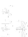
内開き扉の遮蔽構造は、内開きの扉Dの戸先側の端面にエッジ材11、可動部材12、ばね材としての板ばね13、13…を付設してなる(図1、図2)。ただし、図2(A)〜(C)は、それぞれ扉Dの戸先側から見た模式正面図、同図(A)の模式側面図、同図(B)の模式拡大横断面図であり、図2には、2個の板ばね13、13のみが図示されている。
The shielding structure of the inward opening door is formed by attaching an
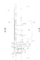
扉Dは、図示しない戸尻側の両開き形のヒンジを介し、室内側、室外側の双方に開閉可能に支承されている。なお、ヒンジは、扉Dを室内側に常時付勢しており、扉Dを図1の閉じ位置に軽くロックすることができる。閉じ位置の扉Dの戸先側は、壁パネルPの先端の扉枠21に対向している。また、扉Dの戸先側には、室内側のスライドボルトD1 、室外側の把手D2 が装着され、壁パネルPの室内側には、スライドボルトD1 を係止させて扉Dを閉じ位置に施錠するキャッチP1 がねじ止めされている。なお、壁パネルPには、キャッチP1 の取付強度を向上させるために補強材P2 が組み込まれている。スライドボルトD1 は、室内側から施錠位置(図1の実線)と解錠位置(同図の二点鎖線)とに切替操作可能であり、非常の際には、把手D2 に組み込む表示付きの解錠機構を介し、室外側から解錠操作することも可能である。
The door D is supported on both the indoor side and the outdoor side so as to be openable and closable via a double-door hinge on the door tail side (not shown). The hinge always urges the door D to the indoor side, and the door D can be lightly locked to the closed position shown in FIG. The door end side of the door D in the closed position faces the
エッジ材11は、扉Dの厚さに適合する浅い左右非対称のチャンネル状に形成されている。エッジ材11の室内側、室外側の上縁には、それぞれ内向き、斜め内向きの係合リブ11a、11bが形成され、内部の底面には、左右のガイドリブ11c、11cを伴う板ばね13用の取付面11dが形成され、底面の背面側には、中央部の取付用のガイドリブ11e、11e、両端部の着座用のリブ11f、11fが形成されている。なお、板ばね13用の取付面11dは、扉Dの中心軸Cd に対し、傾き角θ≒2〜5°だけ室外側に傾けて形成されている。
The
可動部材12は、室内側、室外側の両端にそれぞれ外向き、斜め外向きの係合リブ12a、12bを突出させるとともに、室内側、室外側の両端部内側にそれぞれ大径、小径のビスポケット12c、12dを形成し、中間部の内面を板ばね13用の当接面12eに形成し、外面を滑らかに膨出させて形成されている。なお、係合リブ12a、12bをエッジ材11側の係合リブ11a、11bに内側から係合させて可動部材12をエッジ材11に組み合わせるとき、板ばね13用の当接面12eは、エッジ材11側の板ばね13用の取付面11dと平行であり、可動部材12、エッジ材11の室外側の外面は、滑らかに連続する湾曲面を形成して扉枠21に対向している。
The
板ばね13、13…は、エッジ材11を扉Dの戸先側の端面に固定する取付ビス13a、13a…を介し、エッジ材11の取付面11dに下向きに共締めされている。板ばね13、13…は、エッジ材11、可動部材12の間に装着され、扉枠21に向けて可動部材12を扉Dの中心軸Cd 方向、すなわち扉Dの中心方向から傾き角θ相当だけ室外側に斜めに付勢することができる。ただし、板ばね13、13…は、図2(A)、(B)に拘らず、扉Dの上下方向、すなわちエッジ材11、可動部材12の長さ方向に約300mmピッチごとに必要個数を設けるものとし、図示以外の任意の形状のばね材を使用してもよい。
The
エッジ材11の下端には、底キャップ14が付設されている(図2、図3)。ただし、図3(A)〜(C)は、それぞれ図2(A)相当の要部模式拡大正面図、図3(A)のX矢視相当図、図2(B)相当の要部模式拡大側面図である。なお、図3には、可動部材12と、その下端のエンド部材15の図示が省略されている。
A
底キャップ14は、長方形の一隅部を切り欠いてエッジ材11の横断面形状に倣う形状の底板14aの上面に取付用の舌片14bを立設して形成されている。舌片14bは、エッジ材11の板ばね13用の取付面11dと同一の傾き角θだけ傾けて底板14a上に立設されている。そこで、底キャップ14は、舌片14b上のビス孔14cに挿通する取付ビス14dを介し、エッジ材11の取付面11dの下端部にねじ止めされている。
The
可動部材12の下端には、エンド部材15が付設されている(図2、図4)。ただし、図4(A)〜(D)は、それぞれ図2(A)相当の要部模式拡大正面図、図4(A)のY矢視相当図、図4(A)のZ1 、Z2 矢視相当図である。なお、図4には、エッジ材11と、その下端の底キャップ14の図示が省略されている。
An
エンド部材15は、係合リブ12a、12bを除く可動部材12の横断面形状にほぼ倣う形状の底板15aに対し、可動部材12の室内側の大径のビスポケット12cに対応するようにしてビス孔15bを形成し、室外側の小径のビスポケット12dに対応するようにして上向きの位置決めピン15cを立設して形成されている。そこで、エンド部材15は、位置決めピン15cをビスポケット12dに圧入するとともに、ビス孔15bを介してタッピングねじ形式の取付ビス15dをビスポケット12cにねじ込むことにより、可動部材12に対する相対姿勢を正しく規制しながら可動部材12の下端に固定することができる。
The
なお、エッジ材11、可動部材12は、それぞれアルミニウム押出形材により一体形成されている。また、底キャップ14、エンド部材15は、それぞれたとえばポリエチレン樹脂により一体成形されている。エッジ材11に組み合わせる可動部材12は、エンド部材15が底キャップ14上に着座することにより支承され、所定の高さ位置に保持することができる。
The
扉Dの戸先側の扉枠21は、室外側に頂部21aを有し(図1)、背面側の取付脚21b、21b、室外側の頂部21aに対応する取付脚21c、室内側の着座用のリブ21dを介して壁パネルPの先端面に装着されている。扉枠21の扉Dに対向する側は、室内側から室外側の頂部21aにかけて、室内側の約1/2幅以上が壁パネルPと直角の平面に形成されるとともに、残部は、頂部21aに向けて滑らかな湾曲面に形成されている。そこで、扉Dの閉じ位置において、扉D側の可動部材12は、エッジ材11とともに、扉枠21との間に見通し不能な隙間gを形成することができる。ただし、隙間gは、室外側の約半分がほぼ一定幅の湾曲部分に形成され、室内側の約半分は、室内側に向けて滑らかに開拡している。なお、扉枠21は、アルミニウム押出形材により一体形成されている。
The
かかる構成の内開き扉の遮蔽構造の作動は、たとえば次のとおりである。 The operation of the shielding structure of the inward opening door having such a configuration is as follows, for example.
閉じ位置の扉Dは、スライドボルトD1 を解錠位置(図1の二点鎖線)にして解錠することにより、室内側に自在に開閉することができる。なお、このとき、扉Dのエッジ材11、可動部材12は、扉枠21と干渉することがない。
The door D in the closed position can be freely opened and closed indoors by unlocking the door D in the unlocked position (two-dot chain line in FIG. 1) with the slide bolt D1. At this time, the
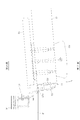
扉Dが閉じ位置にあり、スライドボルトD1 を施錠位置(図1の実線)にして施錠しているとき、室内の使用者が倒れるなどの非常の際には、室外側の把手D2 に内蔵の解錠機構を介してスライドボルトD1 を解錠位置にして扉Dを解錠し、つづいて、把手D2 を引いて扉Dを室外側に開く(図1、図5、図6の各矢印方向)。このとき、扉Dを図1の閉じ位置から室外側に僅かに開くと、可動部材12の表面が扉枠21の室外側の頂部21aに接触するから、さらに扉Dを開くと(図5)、頂部21aを介し、板ばね13に抗して可動部材12がエッジ材11側に駆動され、扉Dを室外側に開放することができる(図6)。ただし、図5は、頂部21aにより可動部材12が最も大きくエッジ材11側に偏移したときを図示しており、このときの頂部21aは、板ばね13の図示しない中心線のほぼ延長上に相当する位置において可動部材12の表面を押圧し、板ばね13を正しく押し縮めることができる。
When the door D is in the closed position and the slide bolt D1 is locked in the locked position (solid line in FIG. 1), it is built into the handle D2 on the outside of the room in case of an emergency such as the user falling down. The door D is unlocked with the slide bolt D1 in the unlocked position via the unlocking mechanism, and then the handle D2 is pulled to open the door D to the outdoor side (directions of arrows in FIGS. 1, 5, and 6). ). At this time, if the door D is slightly opened to the outdoor side from the closed position of FIG. 1, the surface of the
図6の扉Dは、さらに室外側に任意の角度に開き、室内の使用者の救助作業等を実施すればよい。一方、一連の所要作業後の扉Dは、そのまま室内側に押し操作することにより、元の閉じ位置に戻すことができる。このときも、扉枠21の頂部21aが可動部材12の表面に対して室内側の湾曲部分から相対的に乗り上げるようにして接触し、可動部材12をエッジ材11側に円滑に駆動することができるからである。
The door D in FIG. 6 may be further opened to the outside at an arbitrary angle to perform rescue work for the user in the room. On the other hand, the door D after a series of required operations can be returned to the original closed position by pushing it toward the room as it is. Also at this time, the
この発明は、トイレブースを始めとして、建築物の任意の用途の出入口に設置する内開きの扉に対して広く好適に適用することができる。 The present invention can be widely and suitably applied to inward-opening doors installed at entrances and exits of buildings for any purpose, such as toilet booths.
D…扉
g…隙間
11…エッジ材
12…可動部材
12c、12d…ビスポケット
14…底キャップ
15…エンド部材
21…扉枠
21a…頂部
特許出願人 小松ウオール工業株式会社
D ... Door g ...
Patent applicant Komatsu Wall Industry Co., Ltd.
Claims (5)
Priority Applications (1)
| Application Number | Priority Date | Filing Date | Title |
|---|---|---|---|
| JP2016162703A JP6802007B2 (en) | 2016-08-23 | 2016-08-23 | Shielding structure for inward doors |
Applications Claiming Priority (1)
| Application Number | Priority Date | Filing Date | Title |
|---|---|---|---|
| JP2016162703A JP6802007B2 (en) | 2016-08-23 | 2016-08-23 | Shielding structure for inward doors |
Publications (2)
| Publication Number | Publication Date |
|---|---|
| JP2018031147A JP2018031147A (en) | 2018-03-01 |
| JP6802007B2 true JP6802007B2 (en) | 2020-12-16 |
Family
ID=61305047
Family Applications (1)
| Application Number | Title | Priority Date | Filing Date |
|---|---|---|---|
| JP2016162703A Active JP6802007B2 (en) | 2016-08-23 | 2016-08-23 | Shielding structure for inward doors |
Country Status (1)
| Country | Link |
|---|---|
| JP (1) | JP6802007B2 (en) |
Families Citing this family (1)
| Publication number | Priority date | Publication date | Assignee | Title |
|---|---|---|---|---|
| JP6674505B2 (en) * | 2018-06-14 | 2020-04-01 | コマニー株式会社 | Emergency door opening structure |
Family Cites Families (4)
| Publication number | Priority date | Publication date | Assignee | Title |
|---|---|---|---|---|
| JP2599810Y2 (en) * | 1993-12-27 | 1999-09-20 | コマニー株式会社 | Door stop structure of toilet door |
| JP3453589B2 (en) * | 1997-03-31 | 2003-10-06 | 東レAce株式会社 | Door frame for toilet booth |
| JP5954561B2 (en) * | 2011-12-14 | 2016-07-20 | 株式会社シブタニ | Finger padding prevention edge body and door finger padding prevention structure |
| JP6411406B2 (en) * | 2016-06-10 | 2018-10-24 | 株式会社セラ−ズ | Toilet booth |
-
2016
- 2016-08-23 JP JP2016162703A patent/JP6802007B2/en active Active
Also Published As
| Publication number | Publication date |
|---|---|
| JP2018031147A (en) | 2018-03-01 |
Similar Documents
| Publication | Publication Date | Title |
|---|---|---|
| KR101641021B1 (en) | Apparatus for locking windows and doors | |
| US20050036284A1 (en) | Bidirectional latch assembly and electronic apparatuses using the same | |
| US8869351B2 (en) | Detachable hanger for covering of building's opening | |
| US3299573A (en) | Swinging door and hardware for mounting the same | |
| KR101968628B1 (en) | Pivot hinge apparatus | |
| US11708713B2 (en) | Ligature resistant swinging door system | |
| JP6823142B1 (en) | Window opening / closing lock device | |
| JP2022535338A (en) | Airtightness maintenance device for meeting stiles of fittings | |
| KR20170090662A (en) | A frame assembly device which can guide the movement of the frame for sliding security screens | |
| JP6802007B2 (en) | Shielding structure for inward doors | |
| US20150096258A1 (en) | Door assembly | |
| JP6798829B2 (en) | Door gap shielding structure | |
| EP2339103A2 (en) | Hinge for pivot windows | |
| JP5586156B2 (en) | Door edge equipment | |
| US8887793B2 (en) | Screen attachment method for lineals | |
| US11339598B2 (en) | Window vent assist mechanism for vent window assembly | |
| US8136300B2 (en) | Window or door frame having brace device | |
| KR102603148B1 (en) | Foot Locks Device | |
| US20170183894A1 (en) | Confinement locking bar | |
| JP6800477B2 (en) | Sliding door with finger pinch prevention function | |
| JP2017218850A (en) | Toilet booth | |
| GB2546327A (en) | Security cowl and fixing | |
| JP2021031923A (en) | Opening degree limitation hinge and components thereof | |
| JP3225681U (en) | Window fastener | |
| US2373574A (en) | Pivotal awning or shade |
Legal Events
| Date | Code | Title | Description |
|---|---|---|---|
| A621 | Written request for application examination |
Free format text: JAPANESE INTERMEDIATE CODE: A621 Effective date: 20190801 |
|
| A977 | Report on retrieval |
Free format text: JAPANESE INTERMEDIATE CODE: A971007 Effective date: 20200529 |
|
| A131 | Notification of reasons for refusal |
Free format text: JAPANESE INTERMEDIATE CODE: A131 Effective date: 20200630 |
|
| A521 | Request for written amendment filed |
Free format text: JAPANESE INTERMEDIATE CODE: A523 Effective date: 20200727 |
|
| TRDD | Decision of grant or rejection written | ||
| A01 | Written decision to grant a patent or to grant a registration (utility model) |
Free format text: JAPANESE INTERMEDIATE CODE: A01 Effective date: 20201110 |
|
| A61 | First payment of annual fees (during grant procedure) |
Free format text: JAPANESE INTERMEDIATE CODE: A61 Effective date: 20201126 |
|
| R150 | Certificate of patent or registration of utility model |
Ref document number: 6802007 Country of ref document: JP Free format text: JAPANESE INTERMEDIATE CODE: R150 |
|
| R250 | Receipt of annual fees |
Free format text: JAPANESE INTERMEDIATE CODE: R250 |