JP6802007B2 - 内開き扉の遮蔽構造 - Google Patents
内開き扉の遮蔽構造 Download PDFInfo
- Publication number
- JP6802007B2 JP6802007B2 JP2016162703A JP2016162703A JP6802007B2 JP 6802007 B2 JP6802007 B2 JP 6802007B2 JP 2016162703 A JP2016162703 A JP 2016162703A JP 2016162703 A JP2016162703 A JP 2016162703A JP 6802007 B2 JP6802007 B2 JP 6802007B2
- Authority
- JP
- Japan
- Prior art keywords
- door
- movable member
- inward
- door frame
- edge
- Prior art date
- Legal status (The legal status is an assumption and is not a legal conclusion. Google has not performed a legal analysis and makes no representation as to the accuracy of the status listed.)
- Active
Links
Images



Landscapes
- Wing Frames And Configurations (AREA)
- Securing Of Glass Panes Or The Like (AREA)
Description
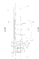
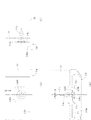
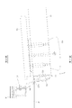
g…隙間
11…エッジ材
12…可動部材
12c、12d…ビスポケット
14…底キャップ
15…エンド部材
21…扉枠
21a…頂部
特許出願人 小松ウオール工業株式会社
Claims (5)
- 内開きの扉の戸先側に付設する左右非対称のチャンネル状のエッジ材と、該エッジ材に組み合わせる可動部材と、該可動部材を扉枠に向けて付勢するばね材とを備えてなり、前記可動部材は、室内側の外向きの係合リブを前記エッジ材の室内側の上縁の内向きの係合リブに内側から係合させるとともに室外側の斜め外向きの係合リブを前記エッジ材の室外側の上縁の斜め内向きの係合リブに内側から係合させて外面を扉枠側に滑らかに膨出させ、扉を閉じると、扉枠との間に見通し不能な隙間を形成する一方、扉を室外側に開操作すると、扉枠の室外側の頂部に接触して前記エッジ材側に駆動され、扉の開放を許容することを特徴とする内開き扉の遮蔽構造。
- 前記エッジ材は、下端に底キャップを付設することを特徴とする請求項1記載の内開き扉の遮蔽構造。
- 前記可動部材は、下端にエンド部材を付設することを特徴とする請求項2記載の内開き扉の遮蔽構造。
- 前記エンド部材は、前記可動部材の室内側、室外側の各ビスポケットにそれぞれ対応するビス孔、位置決めピンを形成することを特徴とする請求項3記載の内開き扉の遮蔽構造。
- 前記ばね材は、前記可動部材を扉の中心方向から室外側に斜めに付勢することを特徴とする請求項1ないし請求項4のいずれか記載の内開き扉の遮蔽構造。
Priority Applications (1)
| Application Number | Priority Date | Filing Date | Title |
|---|---|---|---|
| JP2016162703A JP6802007B2 (ja) | 2016-08-23 | 2016-08-23 | 内開き扉の遮蔽構造 |
Applications Claiming Priority (1)
| Application Number | Priority Date | Filing Date | Title |
|---|---|---|---|
| JP2016162703A JP6802007B2 (ja) | 2016-08-23 | 2016-08-23 | 内開き扉の遮蔽構造 |
Publications (2)
| Publication Number | Publication Date |
|---|---|
| JP2018031147A JP2018031147A (ja) | 2018-03-01 |
| JP6802007B2 true JP6802007B2 (ja) | 2020-12-16 |
Family
ID=61305047
Family Applications (1)
| Application Number | Title | Priority Date | Filing Date |
|---|---|---|---|
| JP2016162703A Active JP6802007B2 (ja) | 2016-08-23 | 2016-08-23 | 内開き扉の遮蔽構造 |
Country Status (1)
| Country | Link |
|---|---|
| JP (1) | JP6802007B2 (ja) |
Families Citing this family (1)
| Publication number | Priority date | Publication date | Assignee | Title |
|---|---|---|---|---|
| JP6674505B2 (ja) * | 2018-06-14 | 2020-04-01 | コマニー株式会社 | 非常時外開き扉の遮蔽構造 |
Family Cites Families (4)
| Publication number | Priority date | Publication date | Assignee | Title |
|---|---|---|---|---|
| JP2599810Y2 (ja) * | 1993-12-27 | 1999-09-20 | コマニー株式会社 | トイレ用ドアの戸当り部構造 |
| JP3453589B2 (ja) * | 1997-03-31 | 2003-10-06 | 東レAce株式会社 | トイレブース用扉枠 |
| JP5954561B2 (ja) * | 2011-12-14 | 2016-07-20 | 株式会社シブタニ | 指詰め防止用エッジ体およびドアの指詰め防止構造 |
| JP6411406B2 (ja) * | 2016-06-10 | 2018-10-24 | 株式会社セラ−ズ | トイレブース |
-
2016
- 2016-08-23 JP JP2016162703A patent/JP6802007B2/ja active Active
Also Published As
| Publication number | Publication date |
|---|---|
| JP2018031147A (ja) | 2018-03-01 |
Similar Documents
| Publication | Publication Date | Title |
|---|---|---|
| KR101641021B1 (ko) | 창호 잠금장치 | |
| US20050036284A1 (en) | Bidirectional latch assembly and electronic apparatuses using the same | |
| US8869351B2 (en) | Detachable hanger for covering of building's opening | |
| US3299573A (en) | Swinging door and hardware for mounting the same | |
| KR101968628B1 (ko) | 피봇 힌지 장치 | |
| US11708713B2 (en) | Ligature resistant swinging door system | |
| JP6823142B1 (ja) | 窓開閉ロック装置 | |
| JP2022535338A (ja) | 建具の召合せ框の気密維持装置 | |
| KR20170090662A (ko) | 모서리 연결부재에 장착된 고정부재를 이용한 탈부착이 용이한 절첩식 방범 방충용 도어의 고정장치 | |
| JP6802007B2 (ja) | 内開き扉の遮蔽構造 | |
| US20150096258A1 (en) | Door assembly | |
| JP6798829B2 (ja) | 扉の隙間遮蔽構造 | |
| EP2339103A2 (en) | Hinge for pivot windows | |
| JP5586156B2 (ja) | ドアのエッジ装置 | |
| US8887793B2 (en) | Screen attachment method for lineals | |
| US11339598B2 (en) | Window vent assist mechanism for vent window assembly | |
| US8136300B2 (en) | Window or door frame having brace device | |
| KR102603148B1 (ko) | 도어용 기능성 풋락장치 | |
| US20170183894A1 (en) | Confinement locking bar | |
| JP6800477B2 (ja) | 指挟み防止機能付き引戸 | |
| JP2017218850A (ja) | トイレブース | |
| GB2546327A (en) | Security cowl and fixing | |
| JP2021031923A (ja) | 開度制限蝶番及びその部品 | |
| JP3225681U (ja) | 窓締結器 | |
| US2373574A (en) | Pivotal awning or shade |
Legal Events
| Date | Code | Title | Description |
|---|---|---|---|
| A621 | Written request for application examination |
Free format text: JAPANESE INTERMEDIATE CODE: A621 Effective date: 20190801 |
|
| A977 | Report on retrieval |
Free format text: JAPANESE INTERMEDIATE CODE: A971007 Effective date: 20200529 |
|
| A131 | Notification of reasons for refusal |
Free format text: JAPANESE INTERMEDIATE CODE: A131 Effective date: 20200630 |
|
| A521 | Request for written amendment filed |
Free format text: JAPANESE INTERMEDIATE CODE: A523 Effective date: 20200727 |
|
| TRDD | Decision of grant or rejection written | ||
| A01 | Written decision to grant a patent or to grant a registration (utility model) |
Free format text: JAPANESE INTERMEDIATE CODE: A01 Effective date: 20201110 |
|
| A61 | First payment of annual fees (during grant procedure) |
Free format text: JAPANESE INTERMEDIATE CODE: A61 Effective date: 20201126 |
|
| R150 | Certificate of patent or registration of utility model |
Ref document number: 6802007 Country of ref document: JP Free format text: JAPANESE INTERMEDIATE CODE: R150 |
|
| R250 | Receipt of annual fees |
Free format text: JAPANESE INTERMEDIATE CODE: R250 |