JP6809130B2 - 容器 - Google Patents
容器 Download PDFInfo
- Publication number
- JP6809130B2 JP6809130B2 JP2016208667A JP2016208667A JP6809130B2 JP 6809130 B2 JP6809130 B2 JP 6809130B2 JP 2016208667 A JP2016208667 A JP 2016208667A JP 2016208667 A JP2016208667 A JP 2016208667A JP 6809130 B2 JP6809130 B2 JP 6809130B2
- Authority
- JP
- Japan
- Prior art keywords
- container
- fixed
- container body
- flange portion
- pump
- Prior art date
- Legal status (The legal status is an assumption and is not a legal conclusion. Google has not performed a legal analysis and makes no representation as to the accuracy of the status listed.)
- Active
Links
Images


Landscapes
- Cooling, Air Intake And Gas Exhaust, And Fuel Tank Arrangements In Propulsion Units (AREA)
Description
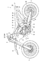
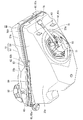
塞いで前記容器本体に固定される被固定物と、前記容器本体と前記被固定物との間に挟み込まれ前記容器本体と前記被固定物との隙間を密閉する密閉材と、を備え、前記容器本体は、前記開口の縁に一体成形され前記被固定物を支持する支持面と前記密閉材に接する接触面とを有し前記被固定物を固定可能な容器フランジ部と、前記容器フランジ部の周囲に一体成形され前記容器本体の内側または外側に膨出する膨出部と、前記開口の縁近傍から前記膨出部の近傍に拡がり前記容器フランジ部に埋設される環状の補強部材と、を備え、前記膨出部の内周は、多角形状である。
Claims (7)
- 開口を有する容器本体と、
前記開口を塞いで前記容器本体に固定される被固定物と、
前記容器本体と前記被固定物との間に挟み込まれ前記容器本体と前記被固定物との隙間を密閉する密閉材と、を備え、
前記容器本体は、前記開口の縁に一体成形され前記被固定物を支持する支持面と前記密閉材に接する接触面とを有し前記被固定物を固定可能な容器フランジ部と、
前記容器フランジ部の周囲に一体成形され前記容器本体の内側または外側に膨出する膨出部と、
前記開口の縁近傍から前記膨出部の近傍に拡がり前記容器フランジ部に埋設される環状の補強部材と、を備え、
前記膨出部の内周は、多角形状である容器。 - 前記被固定物は、前記容器本体に貯蔵される気体または液体を昇圧して吐出するポンプであり、前記開口を通じて前記容器本体内に配置可能な形状を有している請求項1に記載の容器。
- 前記容器本体に設けられるリブと、
前記リブに差し込まれる孔を有し前記容器本体を支持する支持部と、を備える請求項1または2に記載の容器。 - 前記容器本体は樹脂製であり、
前記補強部材は、インサート成形によって前記フランジ部に埋設され、
前記容器フランジ部の一部は、前記補強部材と前記被固定物とによって挟まれている請求項1から3のいずれか1項に記載の容器。 - 前記被固定物は、前記容器フランジ部に固定される被固定物フランジ部を備え、
前記被固定物フランジ部の外周は、前記膨出部の内周に対応する多角形状であり、
前記被固定物フランジ部のそれぞれの頂点部分は、取付孔を有する請求項1から4のいずれか1項に記載の容器。 - 前記膨出部は、前記容器本体の外側に膨出する請求項1から5のいずれか1項に記載の容器。
- 前記膨出部の外周は、円形状である請求項1から6のいずれか1項に記載の容器。
Priority Applications (1)
| Application Number | Priority Date | Filing Date | Title |
|---|---|---|---|
| JP2016208667A JP6809130B2 (ja) | 2016-10-25 | 2016-10-25 | 容器 |
Applications Claiming Priority (1)
| Application Number | Priority Date | Filing Date | Title |
|---|---|---|---|
| JP2016208667A JP6809130B2 (ja) | 2016-10-25 | 2016-10-25 | 容器 |
Publications (2)
| Publication Number | Publication Date |
|---|---|
| JP2018071371A JP2018071371A (ja) | 2018-05-10 |
| JP6809130B2 true JP6809130B2 (ja) | 2021-01-06 |
Family
ID=62114853
Family Applications (1)
| Application Number | Title | Priority Date | Filing Date |
|---|---|---|---|
| JP2016208667A Active JP6809130B2 (ja) | 2016-10-25 | 2016-10-25 | 容器 |
Country Status (1)
| Country | Link |
|---|---|
| JP (1) | JP6809130B2 (ja) |
Families Citing this family (2)
| Publication number | Priority date | Publication date | Assignee | Title |
|---|---|---|---|---|
| JP7131353B2 (ja) * | 2018-12-10 | 2022-09-06 | スズキ株式会社 | 鞍乗型車両の燃料タンク構造 |
| JP7340043B2 (ja) * | 2020-02-05 | 2023-09-06 | 本田技研工業株式会社 | 鞍乗型車両 |
Family Cites Families (4)
| Publication number | Priority date | Publication date | Assignee | Title |
|---|---|---|---|---|
| JPS6072383U (ja) * | 1983-10-26 | 1985-05-22 | スズキ株式会社 | オ−トバイの燃料タンク取着装置 |
| JP5019048B2 (ja) * | 2007-10-05 | 2012-09-05 | 本田技研工業株式会社 | 燃料ポンプの取付構造 |
| JP2009166753A (ja) * | 2008-01-18 | 2009-07-30 | Yamaha Motor Co Ltd | 燃料タンク,該燃料タンクを備えた自動二輪車及び該燃料タンクの製造方法 |
| JP5017162B2 (ja) * | 2008-03-27 | 2012-09-05 | 本田技研工業株式会社 | 燃料ポンプ取付構造 |
-
2016
- 2016-10-25 JP JP2016208667A patent/JP6809130B2/ja active Active
Also Published As
| Publication number | Publication date |
|---|---|
| JP2018071371A (ja) | 2018-05-10 |
Similar Documents
| Publication | Publication Date | Title |
|---|---|---|
| US6644693B2 (en) | Scooter type vehicle | |
| CN101850812B (zh) | 跨骑型车辆的过滤罐的配置构造 | |
| JP5774129B2 (ja) | 鞍乗型車両 | |
| US8690192B2 (en) | Saddle riding vehicle | |
| JP6208647B2 (ja) | 鞍乗り型車両の後部燃料タンク支持構造 | |
| CN102770332B (zh) | 骑乘型车辆的蒸发燃料控制装置 | |
| US9156513B2 (en) | Front cowl stay attachment structure for saddle-ride type vehicle | |
| JP2018103873A (ja) | 鞍乗り型車両のキャニスタ配置構造 | |
| US11884360B2 (en) | Electrical component mounting structure for saddled vehicle | |
| JP2016068832A (ja) | 後部燃料タンク | |
| US7549675B2 (en) | Straddle-type vehicle | |
| JP4007788B2 (ja) | スクータ型自動二輪車の燃料供給装置 | |
| JP6809130B2 (ja) | 容器 | |
| US10124850B2 (en) | Fuel tank for straddle type vehicle | |
| JP4996521B2 (ja) | 自動二輪車のラジエータリザーブタンク配置構造 | |
| US8141543B2 (en) | Arrangement structure of vehicle-use fuel pump | |
| EP1783040B1 (en) | Straddle-type vehicle | |
| JP6649971B2 (ja) | 鞍乗り型車両 | |
| JP5386428B2 (ja) | 燃料ポンプの支持構造 | |
| US11511622B2 (en) | Mounting structure for fuel shutoff valve unit | |
| JP5854294B2 (ja) | スイング式パワーユニット | |
| WO2017134834A1 (ja) | 鞍乗型車両の燃料タンク構造 | |
| JP2006131028A (ja) | 自動二輪車の燃料タンク構造 | |
| JP6437501B2 (ja) | 鞍乗型車両の燃料タンク | |
| CN217074625U (zh) | 跨骑型车辆 |
Legal Events
| Date | Code | Title | Description |
|---|---|---|---|
| A621 | Written request for application examination |
Free format text: JAPANESE INTERMEDIATE CODE: A621 Effective date: 20190627 |
|
| A977 | Report on retrieval |
Free format text: JAPANESE INTERMEDIATE CODE: A971007 Effective date: 20200522 |
|
| A131 | Notification of reasons for refusal |
Free format text: JAPANESE INTERMEDIATE CODE: A131 Effective date: 20200609 |
|
| A521 | Written amendment |
Free format text: JAPANESE INTERMEDIATE CODE: A523 Effective date: 20200807 |
|
| TRDD | Decision of grant or rejection written | ||
| A01 | Written decision to grant a patent or to grant a registration (utility model) |
Free format text: JAPANESE INTERMEDIATE CODE: A01 Effective date: 20201110 |
|
| A61 | First payment of annual fees (during grant procedure) |
Free format text: JAPANESE INTERMEDIATE CODE: A61 Effective date: 20201123 |
|
| R151 | Written notification of patent or utility model registration |
Ref document number: 6809130 Country of ref document: JP Free format text: JAPANESE INTERMEDIATE CODE: R151 |