JP6830274B2 - Busbar manufacturing method - Google Patents
Busbar manufacturing method Download PDFInfo
- Publication number
- JP6830274B2 JP6830274B2 JP2019169253A JP2019169253A JP6830274B2 JP 6830274 B2 JP6830274 B2 JP 6830274B2 JP 2019169253 A JP2019169253 A JP 2019169253A JP 2019169253 A JP2019169253 A JP 2019169253A JP 6830274 B2 JP6830274 B2 JP 6830274B2
- Authority
- JP
- Japan
- Prior art keywords
- electric conductor
- bus bar
- friction
- conductor
- present
- Prior art date
- Legal status (The legal status is an assumption and is not a legal conclusion. Google has not performed a legal analysis and makes no representation as to the accuracy of the status listed.)
- Active
Links
Images


Classifications
-
- H—ELECTRICITY
- H01—ELECTRIC ELEMENTS
- H01B—CABLES; CONDUCTORS; INSULATORS; SELECTION OF MATERIALS FOR THEIR CONDUCTIVE, INSULATING OR DIELECTRIC PROPERTIES
- H01B13/00—Apparatus or processes specially adapted for manufacturing conductors or cables
-
- H—ELECTRICITY
- H01—ELECTRIC ELEMENTS
- H01B—CABLES; CONDUCTORS; INSULATORS; SELECTION OF MATERIALS FOR THEIR CONDUCTIVE, INSULATING OR DIELECTRIC PROPERTIES
- H01B13/00—Apparatus or processes specially adapted for manufacturing conductors or cables
- H01B13/0016—Apparatus or processes specially adapted for manufacturing conductors or cables for heat treatment
-
- B—PERFORMING OPERATIONS; TRANSPORTING
- B23—MACHINE TOOLS; METAL-WORKING NOT OTHERWISE PROVIDED FOR
- B23K—SOLDERING OR UNSOLDERING; WELDING; CLADDING OR PLATING BY SOLDERING OR WELDING; CUTTING BY APPLYING HEAT LOCALLY, e.g. FLAME CUTTING; WORKING BY LASER BEAM
- B23K20/00—Non-electric welding by applying impact or other pressure, with or without the application of heat, e.g. cladding or plating
- B23K20/002—Non-electric welding by applying impact or other pressure, with or without the application of heat, e.g. cladding or plating specially adapted for particular articles or work
-
- B—PERFORMING OPERATIONS; TRANSPORTING
- B23—MACHINE TOOLS; METAL-WORKING NOT OTHERWISE PROVIDED FOR
- B23K—SOLDERING OR UNSOLDERING; WELDING; CLADDING OR PLATING BY SOLDERING OR WELDING; CUTTING BY APPLYING HEAT LOCALLY, e.g. FLAME CUTTING; WORKING BY LASER BEAM
- B23K20/00—Non-electric welding by applying impact or other pressure, with or without the application of heat, e.g. cladding or plating
- B23K20/12—Non-electric welding by applying impact or other pressure, with or without the application of heat, e.g. cladding or plating the heat being generated by friction; Friction welding
-
- H—ELECTRICITY
- H01—ELECTRIC ELEMENTS
- H01B—CABLES; CONDUCTORS; INSULATORS; SELECTION OF MATERIALS FOR THEIR CONDUCTIVE, INSULATING OR DIELECTRIC PROPERTIES
- H01B1/00—Conductors or conductive bodies characterised by the conductive materials; Selection of materials as conductors
- H01B1/02—Conductors or conductive bodies characterised by the conductive materials; Selection of materials as conductors mainly consisting of metals or alloys
-
- H—ELECTRICITY
- H01—ELECTRIC ELEMENTS
- H01R—ELECTRICALLY-CONDUCTIVE CONNECTIONS; STRUCTURAL ASSOCIATIONS OF A PLURALITY OF MUTUALLY-INSULATED ELECTRICAL CONNECTING ELEMENTS; COUPLING DEVICES; CURRENT COLLECTORS
- H01R25/00—Coupling parts adapted for simultaneous co-operation with two or more identical counterparts, e.g. for distributing energy to two or more circuits
Landscapes
- Engineering & Computer Science (AREA)
- Mechanical Engineering (AREA)
- Manufacturing & Machinery (AREA)
- Physics & Mathematics (AREA)
- Thermal Sciences (AREA)
- Pressure Welding/Diffusion-Bonding (AREA)
Description
本発明はバスバー製造方法に関し、特にアルミニウムと銅を摩擦溶接して互いに堅固に結合できるバスバー製造方法に関する。 The present invention relates to a bus bar manufacturing method, and more particularly to a bus bar manufacturing method in which aluminum and copper can be friction-welded and firmly bonded to each other.
電気エネルギーを伝達する媒介体であるバスバー(Bus bar)は、発電所、大型建物、大型工場、大型デパート、地下鉄、新空港などで電流の容量が大きな大型送配電線、電気機器用導体、通信ケーブルなどの送電回路を構成し、一般的には主にケーブルが多く使われてきたが、最近ではバスバーが多様な長所を有しているため、ケーブルの代替品として多く使われている。 Bus bars, which are mediators that transmit electrical energy, are used in power plants, large buildings, large factories, large department stores, subways, new airports, etc., and have large current transmission and distribution lines, conductors for electrical equipment, and communications. Cables have been mainly used to form power transmission circuits such as cables, but recently, busbars have various advantages and are often used as a substitute for cables.
バスバーとケーブルを構造の面で比較してみると、類似点は導体と絶縁体を有するという点であるが、バスバーの最大の長所は同じ体積の導体でより多くの電気エネルギーを伝達できるという点である。したがって、大容量の配電システムにおいてバスバーの長所が認識されてその使用量が急速に増加しており、過去と比較して大容量の電気エネルギーを必要とする大型建物、大型工場、発電所、地下鉄などの需要が急増する趨勢に合わせて、バスバーは安全かつエネルギーの損失が少ないため現代の大容量送電システムに非常に適合した部品と認識されている。 Comparing busbars and cables in terms of structure, the similarities are that they have conductors and insulators, but the biggest advantage of busbars is that they can transfer more electrical energy with the same volume of conductors. Is. Therefore, the advantages of busbars in large-capacity distribution systems have been recognized and their usage is increasing rapidly, and large buildings, large factories, power plants, and subways that require large amounts of electrical energy compared to the past. Busbars are recognized as highly suitable parts for modern high-capacity power transmission systems because they are safe and have low energy loss in line with the rapidly increasing demand.
韓国登録特許第10−0977089号(2010.08.13登録)にはバスバーおよびバスバー加工方法について記載されており、開示された技術によると、電気伝導体物質を押出成形して、側端部が
![]()
![]()
韓国登録特許第10−0603021号(2006.07.12登録)には銀コーティング層が添加された銅−アルミニウムクラッドバスバーおよびその製造方法について記載されている。開示された技術によると、電気エネルギーを伝達する通電用バスバーにおいて、前記バスバーの胴体は一定の長さと厚さのアルミニウムで形成され、前記アルミニウムの全体の表面に一定厚さの銀層が存在し、前記銀層の表面に一定厚さの銅層が存在する銅−銀−アルミニウム積層構造を含むことを特徴とする。 Korean Registered Patent No. 10-0603021 (registered on 2006.07.12) describes a copper-aluminum clad busbar to which a silver coating layer is added and a method for producing the same. According to the disclosed technology, in an energizing busbar that transmits electrical energy, the body of the busbar is made of aluminum of a certain length and thickness, and a silver layer of a certain thickness is present on the entire surface of the aluminum. It is characterized by including a copper-silver-aluminum laminated structure in which a copper layer having a constant thickness is present on the surface of the silver layer.
前述した通り、従来は銅またはアルミニウム素材でバスバーを製造するのが一般的であるが、銅の場合、値段が高く、特性上重量が重いため、製品の耐久性に問題を起こす可能性がある。 As mentioned above, in the past it was common to manufacture busbars from copper or aluminum materials, but copper is expensive and heavy in nature, which can cause problems with product durability. ..
その反面、安価の素材であるアルミニウムの場合、銅素材に比べて電気伝導度が低いため銅よりも2倍以上の体積を有さなければならず、そうでない場合、通電時に熱が発生してしまうため使用環境によって冷却器を設置しなければならない問題が発生し、通電時に発生し得るアークによって溶融点が低いアルミニウム素材に溶融が発生する可能性が高いため重電機器やそれ以上の容量の機器には適していない問題点がある。 On the other hand, aluminum, which is an inexpensive material, has a lower electrical conductivity than copper material, so it must have more than twice the volume of copper. Otherwise, heat is generated when energized. Therefore, there is a problem that a cooler must be installed depending on the usage environment, and there is a high possibility that the aluminum material with a low melting point will melt due to the arc that can occur when energized, so the capacity of heavy electrical equipment or higher There is a problem that the device is not suitable.
前述した通り、従来の銀コーティング層が添加された銅−アルミニウムクラッドバスバーおよびその製造方法は、アルミニウムと銅間の結合時に不良が発生したり、アルミニウムと銅間の結合が堅固でない場合が多いため、外部の衝撃などによって結合部分に亀裂が発生する問題点があった。このため、バスバーの製造過程が複雑となり、保守費用が上昇する短所がある。 As described above, the conventional copper-aluminum clad busbar to which the silver coating layer is added and the manufacturing method thereof often have a defect at the time of bonding between aluminum and copper, or the bond between aluminum and copper is not firm. , There was a problem that cracks were generated in the joint part due to external impact. Therefore, there is a disadvantage that the manufacturing process of the bus bar becomes complicated and the maintenance cost increases.
本発明が達成しようとする技術的課題は、前述したような問題点を解決するためのものであって、アルミニウムと銅を摩擦溶接して互いに堅固に結合できるバスバー製造方法を提供する。 The technical problem to be achieved by the present invention is to solve the above-mentioned problems, and to provide a bus bar manufacturing method capable of friction-welding aluminum and copper to firmly bond them to each other.
このような課題を解決するために、本発明の一特徴によると、第1電気伝導体の両端に第2電気伝導体をそれぞれ配置する配置段階;前記第1電気伝導体と前記第2電気伝導体の間を摩擦溶接する摩擦溶接段階;および前記摩擦溶接段階で摩擦溶接された第1電気伝導体と第2電気伝導体を加圧してバスバーを形成する加圧段階を含む、バスバー製造方法を提供する。 In order to solve such a problem, according to one feature of the present invention, an arrangement step of arranging the second electric conductors at both ends of the first electric conductor; the first electric conductor and the second electric conductor. friction welding step for friction welding between the body; comprising a pressurization step of forming and the friction welding step in friction welding is first bus bar electrical conductor and the second electrical conductor by pressure was, the bus bar manufacturing method I will provide a.
一実施例において、前記加圧段階は、プレス装置をあらかじめ既設定された温度に予熱する予熱過程;および予熱されたプレス装置に摩擦溶接された第1電気伝導体と第2電気伝導体を投入した後に加圧してバスバーを成形する第1加圧過程を含むことを特徴とする。 In one embodiment, the pressurization step is a preheating process that preheats the press device to a preset temperature; and the first and second electrical conductors that are friction welded to the preheated press device. characterized in that it comprises a first pressurizing step of forming the bus bar under pressure after.
一実施例において、前記加圧段階は、加圧成形されたバスバーを既設定された温度でテンパリングするテンパリング過程;およびテンパリングされたバスバーをプレス装置に投入して2次的に加圧成形する第2加圧過程をさらに含むことを特徴とする。 In one embodiment, the pressurization step is a tempering process in which the pressurized busbar is tempered at a preset temperature; and the tempered busbar is charged into a press device for secondary pressurization . 2 It is characterized by further including a pressurizing process.
一実施例において、前記第1電気伝導体は、棒状のアルミニウムであることを特徴とする。 In one embodiment, the first electrical conductor is made of rod-shaped aluminum.
一実施例において、前記第2電気伝導体は、棒状の銅であることを特徴とする。 In one embodiment, the second electrical conductor is a rod-shaped copper.
一実施例において、前記加圧段階は、前記摩擦溶接段階で摩擦溶接された第1電気伝導体と第2電気伝導体を既設定された形に押出成形することを特徴とする。 In one embodiment, the pressurization step is characterized in that the first and second electrical conductors friction-welded in the friction-welding step are extruded into a pre-set shape.
一実施例において、前記加圧段階は、前記第1電気伝導体を平面の形態または3次元の形態に成形することを特徴とする。 In one embodiment, the pressurization step is characterized in that the first electrical conductor is molded into a planar or three-dimensional form.
一実施例において、前記加圧段階で形成されたバスバーの表面をコーティング剤を利用してコーティングするコーティング段階をさらに含むことを特徴とする。 One embodiment is characterized by further comprising a coating step of coating the surface of the bus bar formed in the pressurizing step with a coating agent.
本発明によると、アルミニウムの両端に銅を摩擦溶接してバスバーを製造することによって、原価を節減し、重さを減らし、性能を向上させることができる。 According to the present invention, by friction-welding copper to both ends of aluminum to manufacture a bus bar, it is possible to reduce costs, reduce weight, and improve performance.
すなわち、本発明によってバスバーの大幅な軽量化が可能となることによって、軽量化および剛性が要求される自動車をはじめとする各種移動手段に使用が可能であり、保管および運搬が容易であり、作業性が向上する効果がある。 That is, since the bus bar can be significantly reduced in weight by the present invention, it can be used in various means of transportation such as automobiles that require weight reduction and rigidity, and is easy to store and transport, and works. It has the effect of improving the sex.
また、アルミニウムと銅間の結合力が堅固で高い強度を有するだけでなく、所望の大きさおよび形状のバスバーを製造できる効果がある。 Further, not only the bonding force between aluminum and copper is firm and has high strength, but also there is an effect that a bus bar having a desired size and shape can be manufactured.
以下、添付した図面を参照して本発明の実施例について、本発明が属する技術分野で通常の知識を有する者が容易に実施できるように詳細に説明する。しかし、本発明に関する説明は構造的乃至機能的な説明のための実施例に過ぎないため、本発明の権利範囲は本文に説明された実施例によって制限されるものと解釈されてはならない。すなわち、実施例は多様な変更が可能であり、多様な形態を有することができるため、本発明の権利範囲は技術的思想を具現できる均等物を含むものと理解されるべきである。また、本発明に提示された目的または効果は、特定の実施例がこれをすべて含むべきであるとか、そのような効果のみを含むべきであるという意味ではないため、本発明の権利範囲はこれによって制限されないものと理解されるべきである。 Hereinafter, examples of the present invention will be described in detail with reference to the accompanying drawings so that a person having ordinary knowledge in the technical field to which the present invention belongs can easily carry out the embodiments. However, since the description of the present invention is merely an example for structural or functional explanation, the scope of rights of the present invention should not be construed as being limited by the examples described in the text. That is, it should be understood that the scope of rights of the present invention includes equivalents capable of embodying technical ideas, as the examples can be modified in various ways and can have various forms. Also, since the object or effect presented in the present invention does not mean that a particular embodiment should include all of this or only such effect, the scope of rights of the present invention is this. It should be understood that it is not limited by.
一方、本発明で叙述される用語の意味は次のように理解されるべきである。 On the other hand, the meanings of the terms described in the present invention should be understood as follows.
「第1」、「第2」等の用語は一つの構成要素を他の構成要素から区別するためのものであって、これらの用語によって権利範囲が限定されてはならない。例えば、第1構成要素は第2構成要素と命名され得、同様に第2構成要素も第1構成要素と命名され得る。 Terms such as "first" and "second" are for distinguishing one component from another, and the scope of rights must not be limited by these terms. For example, the first component can be named the second component, and similarly the second component can be named the first component.
ある構成要素が他の構成要素に「連結されて」いると言及された時には、その他の構成要素に直接的に連結されてもよいが、中間に他の構成要素が存在してもよいと理解されるべきである。反面、ある構成要素が他の構成要素に「直接連結されて」いると言及された時には、中間に他の構成要素が存在しないものと理解されるべきである。一方、構成要素の間の関係を説明する他の表現、すなわち「〜間に」と「すぐ〜間に」または「〜に隣り合う」と「〜に直接隣り合う」等も同様に解釈されるべきである。 When it is mentioned that one component is "connected" to another component, it is understood that it may be directly connected to the other component, but there may be other components in between. It should be. On the other hand, when it is mentioned that one component is "directly linked" to another, it should be understood that there is no other component in between. On the other hand, other expressions that describe the relationships between the components, such as "between" and "immediately between" or "adjacent to" and "directly adjacent to", are similarly interpreted. Should be.
単数の表現は文脈上明白に異なることを意味しない限り複数の表現を含むものと理解されるべきであり、「含む」または「有する」等の用語は、説示された特徴、数字、段階、動作、構成要素、部分品またはこれらを組み合わせたものが存在することを指定しようとするものであり、一つまたはそれ以上の他の特徴や数字、段階、動作、構成要素、部分品またはこれらを組み合わせたものなどの存在または付加の可能性をあらかじめ排除しないものと理解されるべきである。 A singular expression should be understood to include multiple expressions unless it means that they are clearly different in context, and terms such as "contain" or "have" are the features, numbers, stages, actions described. , A component, a component, or a combination thereof, which attempts to specify the existence of one or more other features or numbers, stages, actions, components, components, or a combination thereof. It should be understood that it does not preclude the possibility of existence or addition of such things.
ここで使われるすべての用語は異なって定義されない限り、本発明が属する分野で通常の知識を有する者によって一般的に理解されるものと同じ意味を有する。一般的に使われる辞書に定義されている用語は関連技術の文脈上有する意味と一致するものと解釈されるべきであり、本発明で明白に定義しない限り、理想的または過度に形式的な意味を有するものと解釈されない。 All terms used herein have the same meaning as commonly understood by those with ordinary knowledge in the field to which the present invention belongs, unless defined differently. The terms defined in commonly used dictionaries should be construed as consistent with the meanings they have in the context of the relevant art and have ideal or overly formal meanings unless explicitly defined in the present invention. Is not interpreted as having.
以下、本発明の実施例に係るバスバー製造方法について図面を参照して詳細に説明する。 Hereinafter, the bus bar manufacturing method according to the embodiment of the present invention will be described in detail with reference to the drawings.
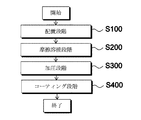
図1は本発明の第1実施例に係るバスバー製造方法を説明するフローチャートであり、図2は本発明の第1実施例に係るバスバー製造方法によって製造されたバスバーである。 FIG. 1 is a flowchart illustrating a bus bar manufacturing method according to the first embodiment of the present invention, and FIG. 2 is a bus bar manufactured by the bus bar manufacturing method according to the first embodiment of the present invention.
図1を参照すると、まず、移送装置を利用して第1電気伝導体の両端に第2電気伝導体をそれぞれ配置するS100。 Referring to FIG. 1, first, S100 in which the second electric conductors are arranged at both ends of the first electric conductor by using a transfer device.
前述した段階S100において、第1電気伝導体は棒状のアルミニウムであり、第2電気伝導体は棒状の銅であることを特徴とする。この時、電気接点が発生する部分に、相対的に電気伝導度が高く溶融点が高い銅素材を位置させることが好ましい。 In the above-mentioned step S100, the first electric conductor is rod-shaped aluminum, and the second electric conductor is rod-shaped copper. At this time, it is preferable to position a copper material having a relatively high electric conductivity and a high melting point at a portion where an electric contact is generated.
前述した段階S100において、第1電気伝導体と第2電気伝導体は棒状であることが好ましいが、必要に応じて多様な形状および大きさで形成され得る。 In the above-mentioned step S100, the first electric conductor and the second electric conductor are preferably rod-shaped, but can be formed in various shapes and sizes as required.
前述した段階S100において、第1電気伝導体の両端に第2電気伝導体が密着するように配置することができる。 In the step S100 described above, the second electric conductor can be arranged so as to be in close contact with both ends of the first electric conductor.
前述した段階S100で配置された第1電気伝導体と第2電気伝導体の間を摩擦溶接機を利用して摩擦溶接するS200。 S200 for friction welding between the first electric conductor and the second electric conductor arranged in the above-mentioned step S100 by using a friction welder.
摩擦溶接は、素材を1分に1600−2200rpmで回転させながら3−10tonの範囲で停止した素材の側面を加圧して接触面で1000−1400℃の摩擦熱が発生するようにし、その後、回転する素材を停止させるとともに接触面の方向で7−20tonの範囲で再度加圧して接触面を焼成変形させることによって溶接する方式である。 In friction welding, the material is rotated at 1600-2200 rpm per minute and the side surface of the material stopped in the range of 3-10 ton is pressurized so that frictional heat of 1000-1400 ° C is generated on the contact surface, and then the rotation is performed. It is a method of welding by stopping the material to be welded and pressurizing it again in the range of 7 to 20 tons in the direction of the contact surface to deform the contact surface by firing.
前述した段階S200において、第1電気伝導体および第2電気伝導体を摩擦溶接機に装着して、回転力によって第1電気伝導体および第2電気伝導体を相互に逆方向に回転させ、第1電気伝導体と第2電気伝導体の密着面で発生する摩擦熱によって接合させることができる。これにより、互いに逆回転する第1電気伝導体と第2電気伝導体を密着させることによって、相対速度を第1電気伝導体と第2電気伝導体の回転速度を足し合わせた分くらいに増加させることができるだけでなく、外部からの制動力がない場合にも、正回転する第1電気伝導体の偶力と逆回転する第2電気伝導体の逆偶力が密着面で力の合成によって慣性が相殺されることによって制動されるようにする効果を提供することができる。 In the above-mentioned step S200, the first electric conductor and the second electric conductor are mounted on the friction welding machine, and the first electric conductor and the second electric conductor are rotated in opposite directions by the rotational force. It can be joined by the frictional heat generated on the contact surface between the 1 electric conductor and the 2nd electric conductor. As a result, the first electric conductor and the second electric conductor that rotate in opposite directions are brought into close contact with each other, so that the relative speed is increased by the sum of the rotation speeds of the first electric conductor and the second electric conductor. Not only can this be done, but even when there is no external braking force, the couple of the first electric conductor that rotates in the forward direction and the reverse couple of the second electric conductor that rotates in the opposite direction are inertial due to the combination of forces on the contact surface. Can provide the effect of being dampened by being offset.
前述した段階S200において、第1電気伝導体および第2電気伝導体を相互に逆方向に既設定された回転速度(例えば、1分に1600〜2200rpmなど)で回転させることができ、第1電気伝導体と第2電気伝導体の密着面の摩擦熱が既設定された温度(例えば、第1電気伝導体および第2電気伝導体の融点など)に到達するまで回転させることができる。 In the above-mentioned step S200, the first electric conductor and the second electric conductor can be rotated in opposite directions at a preset rotation speed (for example, 1600 to 2200 rpm per minute), and the first electricity can be rotated. The frictional heat of the contact surface between the conductor and the second electric conductor can be rotated until it reaches a preset temperature (for example, the melting point of the first electric conductor and the second electric conductor).
前述した段階S200において、第1電気伝導体と第2電気伝導体が密着した状態で相互に逆方向に回転する間に、密着面方向に7〜20ton範囲で加圧力を提供することができる。 In the step S200 described above, while the first electric conductor and the second electric conductor are in close contact with each other and rotate in opposite directions, a pressing force can be provided in the range of 7 to 20 tons in the close contact surface direction.
前述した段階S200で摩擦溶接された第1電気伝導体と第2電気伝導体を加圧してバスバーを形成するS300。 S300 of forming the first bus bar electrical conductor and the second electrical conductor by pressure which is friction welded at the stage S200 described above.
前述した段階S300において、摩擦溶接段階で摩擦溶接された第1電気伝導体と第2電気伝導体を既設定された形(例えば、板状、円柱状)および厚さで加圧または押出成形することができる。 In the above-mentioned step S300, the first electric conductor and the second electric conductor friction-welded in the friction welding step are pressurized or extruded in a preset shape (for example, plate shape or columnar shape) and thickness. be able to.
前述した段階S300において、摩擦溶接段階で摩擦溶接された第1電気伝導体と第2電気伝導体を圧延ロール装置を通過させて圧延成形することができる。この時、圧延成形を容易とするために第1電気伝導体と第2電気伝導体をあらかじめ加熱することができ、圧延成形を通じて第1電気伝導体と第2電気伝導体の角部分を丸く(ラウンディング)成形するなどの多様な形状に成形することができる。 In the step S300 described above, the first electric conductor and the second electric conductor that have been friction-welded in the friction welding step can be rolled and molded by passing through a rolling roll device. At this time, the first electric conductor and the second electric conductor can be preheated in order to facilitate rolling molding, and the corner portions of the first electric conductor and the second electric conductor are rounded through rolling molding ( It can be molded into various shapes such as rolling).
前述した段階S300において、第1電気伝導体を平面の形態または3次元の形態に成形することができる。 In step S300 described above, the first electrical conductor can be molded into a planar or three-dimensional form.
前述した段階S300で形成されたバスバーを所望の大きさで切断することができ、バスバーの両端をパンチングして端子連結のためのホールを形成することができる。 The bus bar formed in the above-mentioned step S300 can be cut to a desired size, and both ends of the bus bar can be punched to form a hole for connecting terminals.
前述したような段階を有するバスバー製造方法は、アルミニウムの両端に銅を摩擦溶接してバスバーを製造することによって、原価を節減し、重さを減らし、性能を向上させることができる。また、アルミニウムと銅間の結合力が堅固で高い強度を有するだけでなく、所望の大きさおよび形状のバスバーを製造することができる。 In the bus bar manufacturing method having the steps as described above, the cost can be reduced, the weight can be reduced, and the performance can be improved by friction-welding copper to both ends of aluminum to manufacture the bus bar. Moreover, not only the bonding force between aluminum and copper is firm and has high strength, but also a bus bar of a desired size and shape can be manufactured.
図3は、図1の加圧段階を説明するフローチャートである。 FIG. 3 is a flowchart illustrating the pressurization step of FIG.
図3を参照すると、プレス装置をあらかじめ既設定された温度(例えば、200〜300℃)に予熱するS310。 Referring to FIG. 3, S310 preheats the press device to a preset temperature (eg, 200-300 ° C.).
前述した段階S310で予熱されたプレス装置に摩擦溶接された第1電気伝導体と第2電気伝導体を投入した後に加圧してバスバーを成形するS320。 S320 of forming the bus bar by pressing after switching on the first electric conductor and second electric conductor which is friction welded to a press apparatus which is preheated in step S310 described above.
前述した段階S320において、あらかじめ予熱されたプレス装置によって摩擦溶接された第1電気伝導体と第2電気伝導体の形状が容易に成形されることはもちろん、成形時に第1電気伝導体と第2電気伝導体の間の接合力が弱くなることを防止することができる。 In the above-mentioned stage S320, the shapes of the first electric conductor and the second electric conductor that are friction-welded by the preheated press device are easily formed, and of course, the first electric conductor and the second electric conductor are formed at the time of forming. It is possible to prevent the bonding force between the electric conductors from becoming weak.
前述した段階S320で加圧成形されたバスバーを既設定された温度でテンパリングするS330。 S330 for tempering the pressure- molded bus bar in step S320 described above at a preset temperature.
前述した段階S330において、テンパリングは約400〜500℃で実施されることが好ましい。テンパリング温度が400℃未満であるとその効果が不充分であり、テンパリング温度が500℃を超過すると強度が低下し得る。 In step S330 described above, tempering is preferably performed at about 400-500 ° C. If the tempering temperature is less than 400 ° C., the effect is insufficient, and if the tempering temperature exceeds 500 ° C., the strength may decrease.
前述した段階S330において、テンパリングは3〜5時間範囲内で実施されることが好ましい。 In step S330 described above, tempering is preferably carried out within a range of 3 to 5 hours.
前述した段階S330でテンパリングされたバスバーをプレス装置に投入して2次的に加圧することによって、所望の大きさおよび形状に成形するS340。 By secondarily pressurized by introducing into the tempered bus bars at the stage S330 described above pressing apparatus, to shape into a desired size and shape S340.
図4は、本発明の第2実施例に係るバスバー製造方法を説明するフローチャートである。 FIG. 4 is a flowchart illustrating a bus bar manufacturing method according to a second embodiment of the present invention.
図4を参照すると、前述した段階S300で形成されたバスバーの表面をコーティング剤を利用してコーティングするS400。 Referring to FIG. 4, S400 which coats the surface of the bus bar formed in the above-mentioned step S300 with a coating agent.
前述した段階S400において、コーティングは、カレンダーコーティング、カーテンコーティング、ディップコーティング、電着コーティング、静電コーティング、溶射コーティング、流動浸漬コーティング、rollコーティング、ナイフスプレーコーティングのうち、必要に応じて選択してコーティングすることができる。 In the above-mentioned step S400, the coating is selected from calendar coating, curtain coating, dip coating, electrodeposition coating, electrostatic coating, thermal spray coating, fluid immersion coating, roll coating, and knife spray coating as necessary. can do.
前述した段階S400において、コーティング剤は、外部に放出される電気の絶縁に優れているポリ塩化ビニル樹脂(PVC)、エポキシ樹脂またはシリコンであり得、その他に絶縁機能を有する材質を使ってもよい。 In the above-mentioned step S400, the coating agent may be polyvinyl chloride resin (PVC), epoxy resin or silicon, which is excellent in insulating the electricity emitted to the outside, and other materials having an insulating function may be used. ..
前述した段階S400において、電気接点が発生する第2電気伝導体にはコーティングされないように、テーピング処理後にコーティング作業を遂行できる。 In the above-mentioned step S400, the coating operation can be performed after the taping treatment so that the second electric conductor in which the electric contact is generated is not coated.
前述した段階S400において、コーティング作業が適合な温度(例えば、150〜300℃)でバスバーの表面を加熱した状態でコーティング作業を遂行できる。 In the step S400 described above, the coating operation can be performed while the surface of the bus bar is heated at a temperature suitable for the coating operation (for example, 150 to 300 ° C.).
前述した段階S400において、バスバーの表面に絶縁材質をコーティングすることによって、バスバーの絶縁能力を増加させて電気自動車のような高電圧用などの多様な電気機器に使うことができる。 In the above-mentioned stage S400, by coating the surface of the bus bar with an insulating material, the insulating capacity of the bus bar can be increased and the bus bar can be used for various electric devices such as those for high voltage.
以上、本発明の実施例は前述した装置および/または運用方法を通じてのみ具現されるものではなく、本発明の実施例の構成に対応する機能を具現するためのプログラム、そのプログラムが記録された記録媒体等を通して具現されてもよく、このような具現は前述した実施例の記載から本発明が属する技術分野の専門家であれば容易に具現できるものである。 As described above, the embodiment of the present invention is not embodied only through the above-mentioned apparatus and / or operation method, but is a program for embodying a function corresponding to the configuration of the embodiment of the present invention, and a record in which the program is recorded. It may be embodied through a medium or the like, and such embodying can be easily embodied by an expert in the technical field to which the present invention belongs from the description of the above-mentioned Examples.
以上、本発明の実施例について詳細に説明したが本発明の権利範囲はこれに限定されず、下記の特許請求の範囲で定義している本発明の基本概念を利用した当業者の多様な変形および改良形態も本発明の権利範囲に属するものである。 Although the examples of the present invention have been described in detail above, the scope of rights of the present invention is not limited to this, and various modifications of those skilled in the art using the basic concept of the present invention defined in the claims below. And the improved form also belongs to the scope of rights of the present invention.
S100:配置段階
S200:摩擦溶接段階
S300:加圧段階
S310:予熱過程
S320:第1加圧過程
S330:テンパリング過程
S340:第2加圧過程
S400:コーティング段階
S100: Arrangement stage S200: Friction welding stage S300: Pressurization stage S310: Preheating process S320: First pressurization process S330: Tempering process S340: Second pressurization process S400: Coating stage
Claims (4)
前記第1電気伝導体と前記第2電気伝導体の間を摩擦溶接する摩擦溶接段階;および
前記摩擦溶接段階で摩擦溶接された第1電気伝導体と第2電気伝導体を加圧してバスバーを形成する加圧段階を含む構成において、
前記加圧段階は、
プレス装置をあらかじめ既設定された温度に予熱する予熱過程;および
予熱されたプレス装置に摩擦溶接された第1電気伝導体と第2電気伝導体を投入した後に加圧してバスバーを成形する第1加圧過程を含む
ことを特徴とする、バスバー製造方法。 Arrangement stage in which the second electric conductor is arranged at both ends of the first electric conductor;
And said friction welding step the first electrical conductor and the busbar of the second electrical conductor to the pressure that has been friction welded; friction welding step for friction welding between the said first electrical conductor second electrical conductor In a configuration that includes a pressurizing step to form
The pressurization step
A preheating process that preheats the press device to a preset temperature; and
A method for manufacturing a bus bar, which comprises a first pressurizing process in which a first electric conductor and a second electric conductor which are friction-welded are charged into a preheated press device and then pressurized to form a bus bar.
加圧成形されたバスバーを既設定された温度でテンパリングするテンパリング過程;および
テンパリングされたバスバーをプレス装置に投入して2次的に加圧成形する第2加圧過程をさらに含むことを特徴とする、請求項1に記載のバスバー製造方法。 The pressurization step
It is characterized by further including a tempering process of tempering the pressure- formed busbar at a pre-set temperature; and a second pressurizing process of feeding the tempered busbar into a press device and secondary pressure- forming. The bus bar manufacturing method according to claim 1.
棒状のアルミニウムであることを特徴とする、請求項1に記載のバスバー製造方法。 The first electric conductor is
The bus bar manufacturing method according to claim 1, wherein the bus bar is made of rod-shaped aluminum.
棒状の銅であることを特徴とする、請求項1に記載のバスバー製造方法。
The second electric conductor is
The bus bar manufacturing method according to claim 1, wherein the rod-shaped copper is used.
Applications Claiming Priority (2)
| Application Number | Priority Date | Filing Date | Title |
|---|---|---|---|
| KR10-2018-0169231 | 2018-12-26 | ||
| KR1020180169231A KR102034011B1 (en) | 2018-12-26 | 2018-12-26 | Manufacturing method of a bus bar |
Publications (2)
| Publication Number | Publication Date |
|---|---|
| JP2020104172A JP2020104172A (en) | 2020-07-09 |
| JP6830274B2 true JP6830274B2 (en) | 2021-02-17 |
Family
ID=68462795
Family Applications (1)
| Application Number | Title | Priority Date | Filing Date |
|---|---|---|---|
| JP2019169253A Active JP6830274B2 (en) | 2018-12-26 | 2019-09-18 | Busbar manufacturing method |
Country Status (3)
| Country | Link |
|---|---|
| JP (1) | JP6830274B2 (en) |
| KR (1) | KR102034011B1 (en) |
| CN (1) | CN111370181B (en) |
Families Citing this family (6)
| Publication number | Priority date | Publication date | Assignee | Title |
|---|---|---|---|---|
| KR102157495B1 (en) * | 2020-02-03 | 2020-09-18 | 에이에프더블류 주식회사 | Pouch type battery cell and manufacturing method thereof |
| KR102290087B1 (en) | 2020-12-09 | 2021-08-17 | 재단법인 경북하이브리드부품연구원 | Manufacturing method for Cu-Al Clad bus bar |
| KR102310033B1 (en) * | 2021-03-03 | 2021-10-08 | 에이에프더블류 주식회사 | Method of manufacturing battery module for electric vehicle and battery module for electric vehicle manufactured thereby |
| KR102422880B1 (en) * | 2022-01-24 | 2022-07-21 | 에이에프더블류 주식회사 | Method of manufacturing fusing busbar |
| KR102466627B1 (en) | 2022-02-21 | 2022-11-15 | 에이에프더블류 주식회사 | Method for manufacturing safety busbar and safety busbar manufactured thereby |
| KR102602736B1 (en) * | 2023-08-30 | 2023-11-15 | (주)디에스시 | Bus bar with excellent preventing thermal runaway function for electric vehicle |
Family Cites Families (24)
| Publication number | Priority date | Publication date | Assignee | Title |
|---|---|---|---|---|
| KR970004548B1 (en) * | 1994-06-15 | 1997-03-29 | 변제현 | Manufacturing method of aluminum copper busbar |
| JP2001267120A (en) * | 2000-03-22 | 2001-09-28 | Hitachi Ltd | Superconducting coil joining method and superconducting magnet |
| KR100603021B1 (en) | 2004-10-20 | 2006-07-24 | 한국과학기술연구원 | Copper-aluminum clad busbar with silver coating layer and its manufacturing method |
| KR101071574B1 (en) * | 2009-04-28 | 2011-10-10 | 김정수 | Bus bar forming device with hot forming |
| KR100977089B1 (en) | 2009-09-08 | 2010-08-19 | 태인전력시스템(주) | Bus bar and method for manufacturing bus bar |
| CN102035080B (en) * | 2009-09-30 | 2013-05-01 | 徐卓辉 | Conductive connecting sheet with side composite metal structure and production method thereof |
| KR101097227B1 (en) * | 2010-02-08 | 2011-12-21 | 에스비리모티브 주식회사 | Battery module and manufacturing method |
| KR20120138790A (en) * | 2010-03-29 | 2012-12-26 | 가부시키가이샤 고베 세이코쇼 | Bus bar and method for producing bus bar |
| JP5483348B2 (en) * | 2010-03-29 | 2014-05-07 | 株式会社神戸製鋼所 | Bus bar manufacturing method |
| CN102357526B (en) * | 2011-09-08 | 2013-09-18 | 东北大学 | Two-step composite rolling method for copper-aluminum-copper double-side ultrathin composite strip |
| KR101362328B1 (en) * | 2012-01-03 | 2014-02-24 | 충남대학교산학협력단 | Cu/Al clad material with high strength and interfacial reliability through alloying, and the method for manufacturing the same |
| JP5530464B2 (en) * | 2012-01-11 | 2014-06-25 | トヨタ自動車株式会社 | Bus bar for power control unit |
| KR101384408B1 (en) * | 2012-07-13 | 2014-04-14 | (주)태광테크 | Method for welding aluminum member using friction stir welding technology |
| KR101429854B1 (en) * | 2013-05-03 | 2014-08-13 | 주식회사 보성알앤디 | Method for friction stir welding aluminum sheets using bulk process |
| CN204189969U (en) * | 2014-10-24 | 2015-03-04 | 江苏万奇电器集团有限公司 | A kind of copper aluminium docking adds the busbar that splices |
| JP2016092157A (en) * | 2014-10-31 | 2016-05-23 | 株式会社神戸製鋼所 | Aluminum - copper composite bus bar and capacitor device |
| JP2016162643A (en) * | 2015-03-03 | 2016-09-05 | 株式会社神戸製鋼所 | Conductive member |
| KR101644859B1 (en) * | 2015-08-18 | 2016-08-02 | 김관중 | different metal Connector and method for manufacturing therefor |
| JP6216764B2 (en) * | 2015-12-24 | 2017-10-18 | 本田技研工業株式会社 | Dissimilar metal joining method and dissimilar metal joining member |
| KR101844270B1 (en) * | 2016-05-18 | 2018-04-02 | 주식회사 리즈텍시스템 | Bus bar and preparing method for the same |
| US10961599B2 (en) * | 2016-07-20 | 2021-03-30 | Hyundai Motor Company | Lightweight door beam, composition thereof and method of manufacturing the same |
| CN106298068A (en) * | 2016-08-23 | 2017-01-04 | 汉舟四川铜铝复合科技有限公司 | A kind of Technology for Heating Processing of copper aluminum interface alloy composite bus |
| KR20180092065A (en) * | 2017-02-08 | 2018-08-17 | 에이치엘그린파워 주식회사 | Battery module and Method for assembling the same |
| KR101927718B1 (en) * | 2017-04-14 | 2018-12-11 | 주식회사 일렉스 | Insulation cover for a bus bar and the bus bar having the insulation cover |
-
2018
- 2018-12-26 KR KR1020180169231A patent/KR102034011B1/en active Active
-
2019
- 2019-02-22 CN CN201910134052.0A patent/CN111370181B/en active Active
- 2019-09-18 JP JP2019169253A patent/JP6830274B2/en active Active
Also Published As
| Publication number | Publication date |
|---|---|
| KR102034011B1 (en) | 2019-10-18 |
| CN111370181B (en) | 2021-12-17 |
| CN111370181A (en) | 2020-07-03 |
| JP2020104172A (en) | 2020-07-09 |
Similar Documents
| Publication | Publication Date | Title |
|---|---|---|
| JP6830274B2 (en) | Busbar manufacturing method | |
| US10348009B2 (en) | Flexible circuits for electrical harnesses | |
| KR101844270B1 (en) | Bus bar and preparing method for the same | |
| JP5055361B2 (en) | Method for connecting two electrically conductive members to each other | |
| US6877210B2 (en) | Electrofriction method of manufacturing squirrel cage rotors | |
| JP2013514188A (en) | Conductive composite component and method of manufacturing the same | |
| US8523045B2 (en) | Method of joining copper conductors | |
| JP4117340B2 (en) | Manufacturing method of copper clad aluminum bus | |
| CN111730192B (en) | Bus bar manufacturing method using linear friction welding | |
| KR101041182B1 (en) | Aluminum copper busbar manufacturing method and aluminum copper busbar manufactured by this method | |
| CN207954926U (en) | Pole piece die-cutting device | |
| KR102034012B1 (en) | Manufacturing method of a bus bar using Friction Stir Welding | |
| WO2023006078A1 (en) | Wire harness manufacturing method and wire harness | |
| CN104466567A (en) | Composite metal bus used for current sensor | |
| KR100603021B1 (en) | Copper-aluminum clad busbar with silver coating layer and its manufacturing method | |
| KR20160124355A (en) | Clad manufacturing apparatus and clad manufacturing method | |
| JP7104537B2 (en) | Electromagnetic wave shield tape, its manufacturing method, and electromagnetic wave shielded cable | |
| CN103943165A (en) | Composite metal wire and manufacturing method | |
| CN111843379B (en) | Bus bar manufacturing method | |
| KR101071574B1 (en) | Bus bar forming device with hot forming | |
| JP7322453B2 (en) | Composite material for terminal and manufacturing method thereof | |
| WO2017105276A1 (en) | Method of ultrasonic welding of single-strand and stranded wires made from non-ferrous metals | |
| JPS647447B2 (en) | ||
| JP4807053B2 (en) | Flat cable manufacturing method | |
| EP3196010B1 (en) | Laminate and method for producing laminate |
Legal Events
| Date | Code | Title | Description |
|---|---|---|---|
| A621 | Written request for application examination |
Free format text: JAPANESE INTERMEDIATE CODE: A621 Effective date: 20190918 |
|
| A131 | Notification of reasons for refusal |
Free format text: JAPANESE INTERMEDIATE CODE: A131 Effective date: 20200908 |
|
| A521 | Request for written amendment filed |
Free format text: JAPANESE INTERMEDIATE CODE: A523 Effective date: 20201208 |
|
| TRDD | Decision of grant or rejection written | ||
| A01 | Written decision to grant a patent or to grant a registration (utility model) |
Free format text: JAPANESE INTERMEDIATE CODE: A01 Effective date: 20210105 |
|
| A61 | First payment of annual fees (during grant procedure) |
Free format text: JAPANESE INTERMEDIATE CODE: A61 Effective date: 20210112 |
|
| R150 | Certificate of patent or registration of utility model |
Ref document number: 6830274 Country of ref document: JP Free format text: JAPANESE INTERMEDIATE CODE: R150 |
|
| R250 | Receipt of annual fees |
Free format text: JAPANESE INTERMEDIATE CODE: R250 |
|
| R250 | Receipt of annual fees |
Free format text: JAPANESE INTERMEDIATE CODE: R250 |
|
| R250 | Receipt of annual fees |
Free format text: JAPANESE INTERMEDIATE CODE: R250 |