JP6830276B1 - Auxiliary tool for scaffolding of transportation vehicles - Google Patents
Auxiliary tool for scaffolding of transportation vehicles Download PDFInfo
- Publication number
- JP6830276B1 JP6830276B1 JP2019186109A JP2019186109A JP6830276B1 JP 6830276 B1 JP6830276 B1 JP 6830276B1 JP 2019186109 A JP2019186109 A JP 2019186109A JP 2019186109 A JP2019186109 A JP 2019186109A JP 6830276 B1 JP6830276 B1 JP 6830276B1
- Authority
- JP
- Japan
- Prior art keywords
- scaffolding
- auxiliary tool
- loading platform
- plate contact
- transport vehicle
- Prior art date
- Legal status (The legal status is an assumption and is not a legal conclusion. Google has not performed a legal analysis and makes no representation as to the accuracy of the status listed.)
- Active
Links
Images







Landscapes
- Loading Or Unloading Of Vehicles (AREA)
- Vehicle Step Arrangements And Article Storage (AREA)
- Pallets (AREA)
Abstract
【課題】本発明は、荷台の近傍に容易かつ確実に足場を形成できる運搬車両の足場形成用補助具を提供することを課題とする。【解決手段】本発明の足場形成用補助具は、運搬車両の荷台から両側方及び後方のうち少なくとも一方に向けて少なくとも一端が突出した状態で上記荷台の上面側に着脱可能に固定される補助具本体と、上記補助具本体の上記一端に取付けられ、上記荷台に隣接して固定される足場を形成するための足場形成部材とを備える。上記補助具本体が、上記荷台に載置されたパレットの挿入口に挿入される挿入部と、上記一端を有するとともに上記パレットの上記挿入口から突出する突出部とを有するとよい。上記挿入部が、棒状の挿入部本体と、上記パレットの上板の下面に当接する上板当接面を有する上板当接部材と、上記上板当接部よりも上記一端側で上記パレットの下板の上面に当接する下板当接面を有する下板当接部とを備えるとよい。【選択図】図1PROBLEM TO BE SOLVED: To provide an auxiliary tool for forming a scaffold for a transport vehicle capable of easily and surely forming a scaffold in the vicinity of a loading platform. SOLUTION: The scaffolding assisting tool of the present invention is detachably fixed to the upper surface side of the loading platform in a state where at least one end protrudes from the loading platform of the transport vehicle toward at least one of both sides and the rear. It includes a tool body and a scaffold forming member for forming a scaffold attached to the one end of the auxiliary tool body and fixed adjacent to the loading platform. It is preferable that the auxiliary tool main body has an insertion portion to be inserted into the insertion port of the pallet placed on the loading platform, and a protrusion having one end and projecting from the insertion port of the pallet. The insertion portion includes a rod-shaped insertion portion main body, an upper plate contact member having an upper plate contact surface that contacts the lower surface of the upper plate of the pallet, and the pallet at one end side of the upper plate contact portion. It is preferable to provide a lower plate contact portion having a lower plate contact surface that contacts the upper surface of the lower plate. [Selection diagram] Fig. 1
Description
本発明は、運搬車両の足場形成用補助具に関する。 The present invention relates to an auxiliary tool for forming a scaffold for a transport vehicle.
圃場において畑作野菜(レタス、白菜、キャベツ等の重量葉物野菜、ニンニク、玉葱、人参、芋等の重量根菜、その他の野菜等)を収穫し、その農作物は収穫箱(プラスチック箱、ダンボール箱等)に詰められる。このように農作物が詰められた収穫箱を運搬するにあたっては、軽トラック等の荷台に直接載置されたパレットに複数段積み重ねられて搬送される。 Harvest vegetables (heavy leafy vegetables such as lettuce, Chinese cabbage, cabbage, heavy root vegetables such as garlic, onions, carrots, and potatoes, and other vegetables) in the field, and the agricultural products are harvest boxes (plastic boxes, cardboard boxes, etc.). ). When transporting a harvest box filled with agricultural products in this way, a plurality of stages are stacked and transported on a pallet directly placed on a loading platform such as a light truck.
作業者の体格等によるが、下方から一定段数未満の収穫箱の積み込みにあっては、比較的容易に積み重ねることができる。しかし、下方から一定段数以上の収穫箱の積み込みにあっては、荷台の側方の地面に立った状態での積み重ね作業は困難である。一定段数以上の収穫箱を積み重ねるために、所定高さの足場を設けることも考えられるが、煩雑であり、また不安定な足下(地面)に足場を設けることが困難な場合もある。 Although it depends on the physique of the worker, it is relatively easy to load the harvest boxes with less than a certain number of stages from the bottom. However, when loading more than a certain number of harvest boxes from below, it is difficult to carry out the stacking work while standing on the ground on the side of the loading platform. It is conceivable to provide scaffolding at a predetermined height in order to stack more than a certain number of harvest boxes, but it is complicated and it may be difficult to provide scaffolding on unstable feet (ground).
なお、側あおり板(側あおり)を水平状態に保持できる機構を荷台の内部に備えるトラックも公知であるが(特開2003−291818号公報参照)、既に所有しているトラックに上記機構を設置することは困難である。 A truck equipped with a mechanism capable of holding the side tilt plate (side tilt) in a horizontal state inside the loading platform is also known (see Japanese Patent Application Laid-Open No. 2003-291818), but the above mechanism is installed in a truck already owned. It's difficult to do.
このような不都合に鑑みて、本発明は、荷台の近傍に容易かつ確実に足場を形成できる運搬車両の足場形成用補助具を提供することを課題とする。 In view of such inconvenience, it is an object of the present invention to provide a scaffolding assisting tool for a transport vehicle capable of easily and surely forming a scaffolding in the vicinity of a loading platform.
上記課題を解決するためになされた本発明の一態様に係る運搬車両の足場形成用補助具は、運搬車両の荷台から両側方及び後方のうち少なくとも一方に向けて少なくとも一端が突出した状態で上記荷台の上面側に着脱可能に固定される補助具本体と、上記補助具本体の上記一端に取付けられ、上記荷台に隣接して固定される足場を形成するための足場形成部材とを備える。 The scaffolding assisting tool for a transport vehicle according to one aspect of the present invention, which has been made to solve the above problems, has at least one end protruding from the loading platform of the transport vehicle toward at least one of both sides and the rear. It includes an auxiliary tool main body that is detachably fixed to the upper surface side of the loading platform, and a scaffolding forming member that is attached to the one end of the auxiliary tool main body and is fixed adjacent to the loading platform.
当該足場形成用補助具にあっては、荷台の上面側に補助具本体を固定し、荷台から両側方及び後方のうち少なくとも一方に向けて突出した補助具本体の上記一端に足場形成部材を取付けることで、荷台に隣接して足場を容易かつ確実に形成することができる。なお、「隣接する」とは、荷台への作業が容易な程度に近接していれば足りる。一方、当該足場形成用補助具の不使用時においては、補助具本体を荷台から離脱することができる。 In the scaffolding auxiliary tool, the auxiliary tool main body is fixed to the upper surface side of the loading platform, and the scaffolding forming member is attached to the one end of the auxiliary tool main body protruding from the loading platform toward at least one of both sides and the rear. As a result, a scaffold can be easily and surely formed adjacent to the loading platform. It should be noted that "adjacent" means that it is sufficient that the cargo bed is close enough to facilitate the work. On the other hand, when the scaffolding auxiliary tool is not used, the auxiliary tool main body can be separated from the loading platform.
当該足場形成用補助具は、上記補助具本体が、上記荷台に載置されたパレットの挿入口に挿入される挿入部と、上記一端を有するとともに上記パレットの上記挿入口から突出する突出部とを有するとよい。これによって、荷台に載置されたパレットの挿入口を利用して、荷台の上面側に補助具本体を容易かつ確実に着脱可能に固定することができる。 The scaffolding assisting tool includes an insertion portion in which the assisting tool main body is inserted into the insertion port of the pallet placed on the loading platform, and a protruding portion having the one end and protruding from the insertion port of the pallet. It is good to have. As a result, the auxiliary tool main body can be easily and surely detachably fixed to the upper surface side of the loading platform by using the insertion port of the pallet placed on the loading platform.
上記挿入部は、棒状の挿入部本体と、上記パレットの上板の下面に当接する上板当接面を有する上板当接部材と、上記上板当接面よりも上記一端側で上記パレットの下板の上面に当接する下板当接面を有する下板当接部材とを備え、上記挿入部本体に対する上板当接面及び上記下板当接面の相対角度が変更可能となるよう上記上板当接部材及び上記下板当接部材が上記挿入部本体に回動可能に取付けられているとよい。これによって、上記挿入部本体がパレットの挿入口に挿入された状態で上記補助具本体の突出部に下向きの力が作用した際に、パレットの上板の下面に上板当接部が当接し、この上板当接部よりも上記一端側でパレットの下板の上面に下板当接部が当接することで、当該足場形成用補助具が容易かつ確実に固定することができる。一方、上板当接面及び下板当接面を平行となるように上板当接部及び下板当接部を回動させることで、挿入部をパレットの挿入口から容易に着脱することができる。 The insertion portion includes a rod-shaped insertion portion main body, an upper plate contact member having an upper plate contact surface that contacts the lower surface of the upper plate of the pallet, and the pallet at one end side of the upper plate contact surface. A lower plate contact member having a lower plate contact surface that contacts the upper surface of the lower plate is provided so that the relative angles of the upper plate contact surface and the lower plate contact surface with respect to the insertion portion main body can be changed. It is preferable that the upper plate contact member and the lower plate contact member are rotatably attached to the insertion portion main body. As a result, when a downward force is applied to the protruding portion of the auxiliary tool main body while the insertion portion main body is inserted into the insertion port of the pallet, the upper plate contact portion comes into contact with the lower surface of the upper plate of the pallet. By contacting the lower plate contact portion with the upper surface of the lower plate of the pallet on one end side of the upper plate contact portion, the scaffold forming auxiliary tool can be easily and surely fixed. On the other hand, by rotating the upper plate contact portion and the lower plate contact portion so that the upper plate contact surface and the lower plate contact surface are parallel to each other, the insertion portion can be easily attached to and detached from the pallet insertion port. Can be done.
上記足場形成部材は、上記突出部に着脱可能に取付けられる着脱部を有するとよい。これによって、当該足場形成補助具を利用しない場合、補助具本体から足場形成部材を離脱しておくことができる。 The scaffolding forming member may have a detachable portion that is detachably attached to the protruding portion. Thereby, when the scaffolding assisting tool is not used, the scaffolding forming member can be separated from the assisting tool main body.
上記足場形成部材は、略水平の上記運搬車両の側あおり板又は後あおり板を係止する係止部を上記着脱部の下方に有するとよい。これによって、補助具本体の挿入部をパレットの挿入口に挿入した状態で、補助具本体の着脱部に足場形成部材の着脱部を取付けて、係止部によって側あおり板又は後あおり板を係止することで略水平に側あおり板又は後あおり板を支持することができ、側あおり板又は後あおり板を足場として利用することができる。 The scaffolding forming member may have a substantially horizontal locking portion for locking the side tilt plate or the rear tilt plate of the transport vehicle below the attachment / detachment portion. As a result, with the insertion part of the auxiliary tool body inserted into the insertion port of the pallet, the attachment / detachment part of the scaffolding forming member is attached to the attachment / detachment part of the auxiliary tool body, and the side tilt plate or the rear tilt plate is engaged by the locking portion. By stopping, the side tilt plate or the rear tilt plate can be supported substantially horizontally, and the side tilt plate or the rear tilt plate can be used as a scaffold.
上記足場形成部材の上面が、上記足場として設けられている。これによって、足場形成部材を取付けた補助具本体の挿入部をパレットの挿入口に挿入することで、足場形成部材の上面によって足場を形成し、この足場を利用してパレット上に例えば収穫箱等の搭載物を搭載することができる。また、所望位置に運搬された後に、搭載物が搭載されたパレットの挿入口に例えばフォークリフトのツメ(フォーク)が挿入され、搭載物が搭載されたパレットを積み下ろすことができる。 The upper surface of the scaffold forming member is provided as the scaffold. As a result, by inserting the insertion portion of the auxiliary tool main body to which the scaffold forming member is attached into the insertion port of the pallet, a scaffold is formed by the upper surface of the scaffold forming member, and the scaffold is used on the pallet, for example, a harvest box or the like. Can be loaded. Further, after being transported to a desired position, for example, a forklift claw (fork) is inserted into the insertion port of the pallet on which the load is mounted, and the pallet on which the load is mounted can be loaded and unloaded.
当該足場形成用補助具にあっては、上記補助具本体が、運搬車両の荷台から両側方に向けて突出し、それぞれ上記足場形成部材が取付けられる両端の突出部を有し、上記足場形成部材が、上記突出部に着脱可能に取付けられる着脱部と、上記着脱部の下方に設けられるとともに略水平の上記運搬車両の側あおり板を係止する係止部を有するとよい。これにより、当該足場形成用補助具は、荷台から両側方に向けて突出した補助具本体の両端にそれぞれ足場形成部材を取付けることで、荷台の両側に隣接して足場を容易かつ確実に形成することができる。 In the scaffold forming auxiliary tool, the auxiliary tool main body protrudes from the loading platform of the transport vehicle toward both sides, and each has protrusions at both ends to which the scaffold forming member is attached, and the scaffold forming member It is preferable to have a detachable portion that is detachably attached to the protruding portion and a locking portion that is provided below the detachable portion and that locks the side tilt plate of the transport vehicle that is substantially horizontal. As a result, the scaffolding assisting tool easily and surely forms scaffolding adjacent to both sides of the loading platform by attaching scaffolding forming members to both ends of the assisting tool body protruding from the loading platform toward both sides. be able to.
以上説明したように、当該足場形成用補助具は、荷台の近傍に容易かつ確実に足場を形成できる。 As described above, the scaffolding auxiliary tool can easily and surely form a scaffolding in the vicinity of the loading platform.
以下、適宜図面を参照しつつ、本発明の実施の形態を詳説する。 Hereinafter, embodiments of the present invention will be described in detail with reference to the drawings as appropriate.
[第一実施形態]
<全体構成の概略>
本発明の一実施形態の足場形成用補助具1は、図1及び図2に示すように、運搬車両100の荷台101の側方に足場を形成するための装置である。なお、本実施形態の説明にあっては、当該足場形成用補助具1が運搬車両100の荷台101に載置されるパレット150を利用して固定されるものについて説明する。また、運搬車両100の一例として、荷台101の側方に側あおり板103を有するとともに荷台101の後方に後あおり板105を有する軽トラックを例にとり説明する。側あおり板103及び後あおり板105は、ヒンジ107を介して荷台101に回動可能に連結されている。以下の説明において、足場として側あおり板103を利用するものを例にとり説明する。
[First Embodiment]
<Outline of overall configuration>
As shown in FIGS. 1 and 2, the scaffolding assisting tool 1 according to the embodiment of the present invention is a device for forming a scaffolding on the side of the
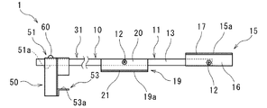
当該足場形成用補助具1は、図1〜図5で示すように、運搬車両100の荷台101から左側に向けて一端が突出した状態で上記荷台101の上面側に着脱可能に固定される補助具本体10と、上記補助具本体10の上記一端に取付けられ、荷台101に隣接して固定される足場を形成するための足場形成部材50とを備える。なお、以下の説明において、「前方」は、当該足場形成用補助具1が装着される運搬車両100の通常の走行時(前進時)の前方(図2の紙面上側)をいい、「後方」は、前方の反対側(図2の紙面下側)をいい、「左右方向」は、前後方向に垂直な水平方向(図2の紙面左右方向)をいうことがある。また、上記一端側(図1〜図5における左側)を先端側と、上記一端側の反対側(図1〜図5における右側)を後端側ということがある。
As shown in FIGS. 1 to 5, the scaffolding assisting tool 1 is detachably fixed to the upper surface side of the
<補助具本体>
当該足場形成用補助具1は、上述のように、荷台101に載置されたパレット150の挿入口151を利用して、足場を形成する。当該足場形成用補助具1の補助具本体10は、パレット150の挿入口151に挿入される挿入部11と、上述のように荷台101から側方に向けた突出した上記一端を有するとともに上記挿入口151から突出する突出部31とを有している。
<Auxiliary tool body>
As described above, the scaffolding assisting tool 1 forms a scaffolding by using the
(挿入部)
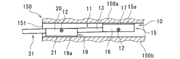
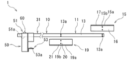
上記挿入部11は、図3〜図5で示すように、棒状の挿入部本体13と、パレット150の上板150aの下面に当接する上板当接面15aを有する上板当接部材15と、上板当接面15aよりも一端側で上記パレット150の下板150bの上面に当接する下板当接面19aを有する下板当接部材19とを備えている。上板当接部材15及び下板当接部材19が挿入部本体13に回動可能に取付けられ、上板当接面15a及び下板当接面19aと挿入部本体13との相対角度が変更可能に設けられている。
(Insert part)
As shown in FIGS. 3 to 5, the
挿入部11の具体的構成は特に限定されず、適宜設計変更可能であるが、本実施形態においては、挿入部本体13は、四角筒状の鋼材から構成されている。また、上板当接部材15は、下方が開口する逆U字状の鋼材からなる上板当接部材本体16と、上板当接部材本体16の上面に固定されるゴム等の弾性部材からなる上板当接面構成部材17とを有し、この上板当接面構成部材17の上面によって上記上板当接面15aが構成される(図3〜図5参照)。このように上板当接面15aが弾性部材によって構成されるので、パレット150の挿入口151への補助具本体10の固定状態をより的確に維持できる。下板当接部材19は、上方が開口するU字状の鋼材からなる下板当接部材本体20と、下板当接部材本体20の下面に固定されるゴム等の弾性部材からなる下板当接面構成部材21とを有し、この下板当接面構成部材21の下面によって上記下板当接面19aが構成される。このように下板当接面19aが弾性部材によって構成されるので、パレット150の挿入口151への補助具本体10の固定状態をより的確に維持できる。また、上述のように、パレット150の上板150a及び下板150bに対して、挿入部11は、線状に接触するのではなく、面(上板当接面15a及び下板当接面15b)で当接するので、挿入部11の固定によるパレット150の破壊を抑止でき、特に、上板当接面15a及び下板当接面15bは弾性部材によって構成されているので、挿入部11の固定によるパレット150の破壊をより的確に抑止できる。
The specific configuration of the
上板当接部材15及び下板当接部材19の構成についてより具体的に説明すると、上板当接部材15は、挿入部本体13の後端側において、棒状の挿入部本体13の軸方向に垂直かつ水平方向に配された軸12に軸支されている。下板当接部材19は、上板当接部材15が軸支されている軸12よりも先端側において、棒状の挿入部本体13の軸方向に垂直かつ水平方向に配された軸12に軸支されている。これにより、上板当接面15a及び下板当接面19aと挿入部本体13との相対角度が変更可能に設けられている。
More specifically, the configurations of the upper
上板当接面15aと下板当接面19aとが挿入部本体13の軸方向と平行となり、上板当接面15aと下板当接面19aとの上下方向の距離が小さくなることで(図3参照)、容易かつ確実に挿入部11をパレット150の挿入口151に挿入でき、また容易かつ確実に挿入部11をパレット150の挿入口151から離脱できる。一方、上板当接面15aと下板当接面19aとが挿入部本体13の軸方向に対して傾斜する状態となり、上板当接面15aと下板当接面19aとの上下方向の距離が大きくなることで(図4及び図5参照)、上板当接面15aがパレット150の上板150aの下面に当接するとともに下板当接面19aがパレット150の下板150bの上面に当接し、容易かつ確実に補助具本体10をパレット150に固定できる。
The upper
(突出部)
突出部31は、挿入部本体13から先端側(荷台101の左側(図1及び図2等参照))に向けて連続して設けられている。本実施形態にあっては、突出部31は、挿入部本体13と同一の鋼材から構成されている。つまり、一つの棒状の鋼材によって、突出部31及び挿入部本体13が設けられ、突出部31及び挿入部本体13は直線状(略同一高さ)に配されている。
(Protruding part)
The protruding
<足場形成部材>
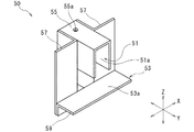
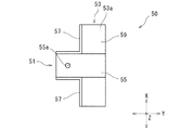
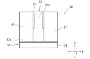
足場形成部材50は、図6〜図9に示すように、突出部31に着脱可能に取付けられる着脱部51と、上記運搬車両100の側あおり板103を略水平に係止する係止部53とを有し、係止部53は、着脱部51の下方に設けられている。具体的には、着脱部51には、補助具本体10の突出部31が挿入され装着される装着孔51aが設けられ、係止部53は、側あおり板103を下方から支持する支持部53aを有している。なお、「略水平」とは、完全な水平状態のみならず、足場として利用できる程度な状態も含む。また、図6〜図9において、Xは運搬車両の走行方向を意味し、YはXに直交する水平方向(運搬車両の左右方向)を意味し、Zは上下方向を意味している。
<Scaffolding member>
As shown in FIGS. 6 to 9, the
この足場形成部材50の具体的構成は特に限定されるものではなく、適宜設計変更可能であるが、本実施形態にあっては、足場形成部材50は、下方が開口する逆U字状の鋼材からなる装着部材55を有している。この装着部材55の開口に突出部31が挿入されることで、突出部31に足場形成部材50が取付けられる。つまり、装着部材55によって上記装着孔51aが構成されている。また、装着部材55及び突出部31には、対応する位置にそれぞれ足場形成部材用ピン孔55a及び突出部用ピン孔が設けられている(図6及び図7参照(突出部用ピン孔については図示省略))。装着部材55及び突出部31のピン孔55aにピン60が装着されることで(図1〜図3参照)、装着部材55の突出部31への固定状態が維持される。この足場の形成部材用ピン孔55aは、着脱部53の支持部53a(後述する支持部材59)よりも一端側(図7の左側)に設けられている。これにより、ピン60の下方にスナップピン等の抜け止め部材を配する場合にあっても、支持部53aに支持される側あおり板が邪魔にならない。
The specific configuration of the
また、上記足場形成部材50は、装着部材55の前方及び後方に固定され下方に延出する平面視L字状の鋼材からなる前後一対の柱部材57を有している(図6〜図9参照)。足場形成部材50は、一対の柱部材57の下方に固定される倒L字状の鋼材からなる支持部材59を有している。この支持部材59は、一対の柱部材57の先端側の面に固定され、この固定部位から先端側の反対側に向けて屈曲し水平に延出する屈曲部位を有し、この支持部材59の屈曲部位によって上記係止部53が構成されている。
Further, the
<利点>
当該足場形成用補助具1は、一定段数(図1では3段)の収穫箱が積み重ねられた荷台101の上面側に補助具本体10を固定し、荷台101の左側から突出した補助具本体10の突出部31に足場形成部材50を取付け、足場形成部材50によって側あおり板103を支持することで、側あおり板103を利用して荷台101に隣接して足場を容易かつ確実に形成することができる。このため、図1に示すように、荷台101上のパレット150に3段の収穫箱130を積み重ねた状態にあっても、作業者が側あおり板103を足場として利用して下方から一定段よりも上の収穫箱130を容易に積み重ね、所望段数の収穫箱を積み重ねることができる。なお、当該足場形成用補助具1を利用する上記一定段数は、荷台101の高さ、収穫箱の高さ、作業者の体格等によって適宜変更される。また、当該足場形成用補助具1は、地面に接さない状態で足場を形成できるので、足場が形成された状態(当該足場形成用補助具1が用いられた状態)のまま運搬車両100を走行させて、移動することができる。上述のような積み重ね作業完了後、挿入部11をパレット150の挿入口151から離脱することで、当該足場形成用補助具1を取り外すことができる。
<Advantage>
In the scaffolding auxiliary tool 1, the auxiliary tool
特に、近年、省力化のために物流分野においてフォークリフトとパレットとが幅広く用いられているため、当該足場形成用補助具は好適に用いられる。また、農作物の収穫作業の現場や、生産者の作業場や、出荷現場において、収穫物を入れた収穫箱のハンドリングの問題が顕著であるので、当該足場形成用補助具がより好適に用いられる。 In particular, in recent years, forklifts and pallets have been widely used in the field of physical distribution for labor saving, so that the scaffolding auxiliary tool is preferably used. In addition, since the problem of handling the harvest box containing the harvested product is remarkable at the site of the harvesting work of agricultural products, the workplace of the producer, and the shipping site, the scaffold forming auxiliary tool is more preferably used.
また、農道、防除道(圃場内に設けられた)等に乗り入れた運搬車両の近傍の地面に載置したパレットに収穫箱130を積み重ねた後に、このパレットをフォークリフトによって荷台に載置させることも考えられるが、フォークリフトは高額であるためコストの面で問題があるとともに、フォークリフトを作業できる者の確保や、フォークリフトの作業できる場所であるか否かの問題があるため、農作物の収穫現場等において当該足場形成用補助具は好適に用いられる。
In addition, after the
さらに、従来、荷台の上に作業者が上がり、地面からの積み込み作業が困難になった高さ以上の収穫箱130を積み重ねることもなされており、土足で上がると荷台、パレット又は収穫箱130が泥で汚れるおそれがあるため、荷台の上に作業者が上がる際に靴を履き替えることがなされているが、この作業は極めて煩雑である。この場合にあっても、全ての収穫箱130を所望の段数まで積み上げるには、最終段階で荷台の上に足場スペースがなくなる。このため、このような作業現場において当該足場形成用補助具はより好適に用いられる。
Further, conventionally, a worker has been raised on the loading platform to stack
[その他の実施形態]
上記実施形態は、本発明の構成を限定するものではない。従って、上記実施形態は、本明細書の記載及び技術常識に基づいて上記実施形態各部の構成要素の省略、置換又は追加が可能であり、それらは全て本発明の範囲に属するものと解釈されるべきである。
[Other Embodiments]
The above embodiment does not limit the configuration of the present invention. Therefore, in the above-described embodiment, the components of each part of the above-described embodiment can be omitted, replaced or added based on the description of the present specification and common general technical knowledge, and all of them are construed as belonging to the scope of the present invention. Should be.
例えば、上記実施形態においては、側あおり板を足場として用いるものについて説明したが、本発明はこれに限定されない。具体的には、図10及び図11に示すように、側あおり板以外の足場用部材を別途備えるものであってもよい(なお、図10及び図11において、上記実施形態と同様の機能を有する部材については同一符号を用い、説明を省略する場合があり、図12〜図16においても同様である)。図10及び図11の足場形成用補助具201は、上記実施形態と同様の補助具本体10の突出部31に着脱可能に取付けられる上記足場用部材としての足場形成部材250を有し、上記足場形成部材250の上面250aが、上記足場として設けられている。図10及び図11の足場形成部材250は、複数(図示においては前後二つの)の補助具本体10の突出部31によって下方から支持される。図10及び図11の足場形成部材250は、突出部31が装着される左右方向に沿って形成された装着凹部を有している。この装着凹部は、下方に開口した溝部であっても、左右方向に貫通する貫通孔であってもよい。
For example, in the above embodiment, the one using the side tilt plate as a scaffold has been described, but the present invention is not limited to this. Specifically, as shown in FIGS. 10 and 11, a scaffolding member other than the side tilt plate may be separately provided (note that in FIGS. 10 and 11, the same functions as those in the above embodiment may be provided. The same reference numerals may be used for the members to be provided, and the description thereof may be omitted, and the same applies to FIGS. 12 to 16). The scaffolding
なお、図10及び図11の足場形成用補助具201は、足場形成部の一端側にローラコンベア(図示省略)の連結フックと連結可能な連結部260(連結シャフト)をさらに備えている。このため、この連結部260においてローラコンベアの連結フックと連結することで、ローラコンベアを用いて収穫箱を足場まで搬送し、この搬送した収穫箱を足場に載置しておく(仮置きしておく)ことができる。なお、連結部としては、ローラコンベアの連結シャフトに連結可能な連結フックを採用することも可能である。なお、この連結部は、その他の実施形態においても採用することができる。
The
また、上記実施形態にあっては、挿入部本体13と突出部21とが略同一高さであり、荷台101と足場としての側あおり板103とが略同一高さであるものについて説明したが、足場が荷台101と同一高さであることは必須の構成要件ではない。具体的には、図12又は図13に示すように、足場が荷台よりも低くなる又は高くなるものであっても本発明の意図する範囲内である。
Further, in the above embodiment, the insertion portion
図12の足場形成用補助具301は、図1〜図9と略同様の機能を有する補助具本体310と、図10及び図11の足場形成部材250とを有している。図12の補助具本体310は、図1〜図9と同様の挿入部11と、この挿入部11から側方に向けて突出する突出部331とを有している。この突出部331は、挿入部11から側方に向けて突出する突出部位331aと、この突出部331aの左端から下方に向けて屈曲する柱部位331bと、この柱部位331bから側方に向けて屈曲するとともに上記足場形成部材250を支持する支持部位331cとを有している。図12の足場形成用補助具301にあっては、例えば図10及び図11の足場形成用補助具201の前方又は後方に設置することで、足場形成用補助具201に作業者が上がるためのステップとして利用することができる。
The scaffolding
図13の足場形成用補助具401は、図1〜図9と略同様の機能を有する補助具本体410と、図10及び図11の足場形成部材250とを有している。図13の補助具本体410は、図1〜図9と同様の挿入部11と、この挿入部11から側方に向けて突出する突出部431とを有している。この突出部431は、挿入部11から側方に向けて突出する突出部位431aと、この突出部位431aの左端から上方に向けて屈曲する柱部位431bと、この柱部位431bから側方に向けて屈曲するとともに上記足場形成部材250を支持する支持部位431cとを有している。図13の足場形成用補助具401にあっては、例えば図10及び図11の足場形成用補助具201の前方又は後方に設置することで、図10及び図11の足場形成用補助具201によって形成された足場を利用して図13の足場形成用補助具401の足場に上がり、より高い位置で各種作業を行うことができる。
The scaffolding
さらに、例えば、運搬車両100の後方から前方にかけて、図12の足場形成用補助具301、図1〜図9の足場形成用補助具1、及び図13の足場形成用補助具401によって足場を形成し、運搬車両100の側方に階段状に足場を設けることが可能である。
Further, for example, a scaffold is formed from the rear to the front of the
また、上記実施形態にあっては、補助具本体の一端が運搬車両の荷台の左側方のみに向けて突出した状態で補助具本体が荷台の上面側に着脱可能に固定されるものについて説明したが、本発明はこれに限定されず、補助具本体の一端が運搬車両の荷台から両側方及び後方のうち少なくとも一方に向けて突出した状態で補助具本体が荷台の上面側に着脱可能に固定されるものであれば適宜設計変更可能である。例えば、図14に示すように、荷台の両側方双方から突出部が突出するものも本発明の意図する範囲内であり、また荷台の後方のみから突出部が突出するものも本発明の意図する範囲内である。 Further, in the above embodiment, the auxiliary tool main body is detachably fixed to the upper surface side of the loading platform in a state where one end of the auxiliary tool main body protrudes only toward the left side of the loading platform of the transport vehicle. However, the present invention is not limited to this, and the auxiliary tool main body is detachably fixed to the upper surface side of the loading platform in a state where one end of the auxiliary tool main body protrudes from the loading platform of the transport vehicle toward at least one of both sides and the rear. The design can be changed as appropriate if it is possible. For example, as shown in FIG. 14, those having protrusions protruding from both sides of the loading platform are within the range intended by the present invention, and those projecting from only the rear of the loading platform are also intended by the present invention. It is within the range.
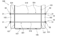
また、上記実施形態にあっては、パレット150の挿入口151を利用して当該足場形成用補助具が固定されるものについて説明したが、本発明はこれに限定されない。例えば、図14に示すように荷台101上に直接載置固定されるものであってもよい。図14の足場形成用補助具501の補助具本体510が、運搬車両100の荷台101から両側方に向けて突出し、それぞれ図1〜図9の足場形成部材50が取付けられる両端の突出部531を有している。そして、足場形成部材50の着脱部51が、突出部531に着脱可能に取付けられ、着脱部51の下方の係止部53に運搬車両100の略水平状態の側あおり板103が係止されることで、両側方の側あおり板103が足場として利用できる。また、本発明の足場形成用補助具は、上述のようにパレットを載置した荷台に用いられるものに限定されず、例えば下方に車輪又は脚部を有する大型の収穫箱を荷台に載置する場合や、荷台に左右方向にトラック荷台用角材(通称バンギ)を載置している場合などにおいても利用できる。
Further, in the above embodiment, the scaffolding assisting tool is fixed by using the
さらに、図15及び図16に示すように両側の側あおり板103のみならず後あおり板105も足場として利用することも可能である。図15及び図16の足場形成用補助具601にあっては、最後方の足場形成部材650の係止部653(支持部材659)が後方に延出され、この係止部653の後方において支持される後あおり板支持部材640をさらに備えている。この後あおり板支持部材640は、係止部553に支持される両端部640aと、この両端部640aの中間において後あおり板105を支持する支持部640bとを有している。上記両端部640aに対して支持部640bは、後あおり板105の厚み分、下方に設けられている。図15及び図16の足場形成用補助具601によれば、両側の側あおり板103のみならず後あおり板105も足場として利用できるので、一方の側あおり板103から他方の側あおり板103に作業者が移動する際に、後あおり板105を介して移動できるので、作業者が地面に降りることなく移動でき、作業性に優れている。
Further, as shown in FIGS. 15 and 16, not only the
なお、パレットの種類によって挿入口の高さが異なる場合がある。このように挿入口の高さが異なるパレットに当該足場形成用補助具を用いる場合、上述の上板当接部材15及び/又は下板当接部材19と高さが変更可能に設けられていることが好ましい。具体的には、図17に示すように、挿入部本体13及び上板当接部材15の少なくとも一方(図17では双方)に、他方を取付ける取付部13a,15b(軸支用孔)を複数位置(図17では2箇所)に設けることが可能である。また、図17に示すように、挿入部本体13及び下板当接部材19の少なくとも一方(図17では双方)に、他方を取付ける取付部13a,19b(軸支用孔)を複数位置(図17では2箇所)に設けることが可能である。さらには、上記実施形態の上板当接部材15又は下板当接部材19と異なる高さの他の上板当接部材又は下板当接部材を別途用意しておき、この他の上板当接部材又は下板当接部材を上記挿入部本体13に付け替えることで(軸支させることで)、上板当接面と下板当接面との上下方向の距離を設計変更することも可能である。
The height of the insertion slot may differ depending on the type of pallet. When the scaffolding auxiliary tool is used for pallets having different heights of the insertion openings, the height can be changed from the above-mentioned upper
上記実施形態にあっては、当該足場形成用補助具を二方差しパレットに着脱するものについて説明したが、当該足場形成用補助具を四方差しパレット等のその他のパレットに着脱することも可能である。また、下板のないパレットや、脚又はキャスターを下部に有するコンテナであっても、当該足場形成用補助具を採用することが可能である。 In the above embodiment, the scaffolding auxiliary tool is attached to and detached from the two-way pallet, but the scaffolding auxiliary tool can be attached to and detached from other pallets such as the four-way pallet. is there. Further, even in a pallet without a lower plate or a container having legs or casters at the lower part, the scaffolding auxiliary tool can be adopted.
上記実施形態にあっては、運搬車両の荷台の一例として軽トラックの荷台を例にとり説明したが、本発明はこれに限定されず、種々の運搬車両の荷台に適用可能であり、例えば、トラクターの後部に組込み油圧で作動されるトラクターバケットの荷台等にも適用することも可能である。さらには、側あおり板を有さないクローラ車等の運搬車両にあっても、当該足場形成用補助具を利用することも可能である。 In the above embodiment, the loading platform of a light truck has been described as an example of the loading platform of the transport vehicle, but the present invention is not limited to this, and can be applied to the loading platform of various transport vehicles, for example, a tractor. It can also be applied to the loading platform of a tractor bucket that is built into the rear part and is operated by flood control. Furthermore, it is also possible to use the scaffolding auxiliary tool even in a transport vehicle such as a crawler vehicle that does not have a side tilt plate.
また、上記実施形態にあっては、圃場で農作物の収穫箱を荷台に積み重ねる際に用いられる場合について説明したが、本発明はこれに限定されるものではなく、当該足場形成用補助具は、工事現場での物品の運搬車両への積載、工場等での商品等の運搬車両への積載等においても好適に用いることができる。 Further, in the above embodiment, the case where the harvest box of agricultural products is used for stacking on the loading platform in the field has been described, but the present invention is not limited to this, and the scaffold forming auxiliary tool is not limited to this. It can also be suitably used for loading an article on a transport vehicle at a construction site, loading a product or the like on a transport vehicle at a factory or the like.
当該足場形成用補助具は、農作物等の種々の搬送物を搬送する作業に好適に用いることができる。 The scaffolding auxiliary tool can be suitably used for the work of transporting various transported objects such as agricultural products.
1 足場形成用補助具
10 補助具本体
11 挿入部
12 軸
13 挿入部本体
13a 取付部
15 上板当接部
15a 上板当接面
15b 取付部
16 上板当接部材本体
17 上板当接面構成部材
19 下板当接部
19a 下板当接面
19b 取付部
20 下板当接部材本体
21 下板当接面構成部材
31 突出部
50 足場形成部材
51 着脱部
51a 装着孔
53 係止部
53a 支持部
55 装着部材
55a 足場形成部材用ピン孔
57 柱部材
59 係止部材
60 ピン
100 運搬車両
101 荷台
103 側あおり板
105 後あおり板
107 ヒンジ
130 収穫箱
150 パレット
150a 上板
150b 下板
151 挿入口
201 足場形成用補助具
250 足場形成部材
250a 上面
260 連結部
301 足場形成用補助具
310 補助具本体
303 脚部材
303a 脚部材本体
303b 進退部材
331 突出部
331a 突出部位
331b 柱部位
331c 支持部位
401 足場形成用補助具
410 補助具本体
431 突出部
431a 突出部位
431b 柱部位
431c 支持部位
501 足場形成用補助具
510 補助具本体
531 突出部
601 足場形成用補助具
640 後あおり板支持部材
640a 両端部
640b 支持部
650 足場形成部材
653 係止部
659 支持部材
1 Scaffolding
Claims (6)
上記補助具本体の上記一端に取付けられ、上記荷台に隣接して固定される足場を形成するための足場形成部材と
を備え、
上記補助具本体が、
足場形成時において上記荷台に載置されたパレットの挿入口に挿入される挿入部と、
上記一端を有するとともに上記足場形成時において上記パレットの上記挿入口から突出する突出部と
を有する運搬車両の足場形成用補助具。 And the auxiliary device main body to be detachably fixed to the upper surface of the loading platform in a state where the one end toward the at least one projecting out of both sides and rearwardly from the loading platform of the transport vehicle,
A scaffold forming member for forming a scaffold attached to the one end of the auxiliary tool main body and fixed adjacent to the loading platform is provided .
The above auxiliary tool body
An insertion part that is inserted into the insertion port of the pallet placed on the loading platform when the scaffold is formed,
With the protruding portion having the one end and protruding from the insertion port of the pallet when the scaffold is formed.
Scaffolding for the aid of the transport vehicle that having a.
上記挿入部本体に対する上板当接面及び上記下板当接面の相対角度が変更可能となるよう上記上板当接部材及び上記下板当接部材が上記挿入部本体に回動可能に取付けられている請求項1に記載の運搬車両の足場形成用補助具。 The insertion portion includes a rod-shaped insertion portion main body, an upper plate contact member having an upper plate contact surface that contacts the lower surface of the upper plate of the pallet, and the pallet at one end side of the upper plate contact surface. A lower plate contact member having a lower plate contact surface that contacts the upper surface of the lower plate is provided.
The upper plate contact member and the lower plate contact member are rotatably attached to the insertion portion main body so that the relative angles of the upper plate contact surface and the lower plate contact surface with respect to the insertion portion main body can be changed. The auxiliary tool for scaffolding of a transport vehicle according to claim 1 .
上記補助具本体の上記一端に取付けられ、上記荷台に隣接して固定される足場を形成するための足場形成部材と
を備え、
上記補助具本体が、運搬車両の荷台から両側方に向けて突出し、それぞれ上記足場形成部材が取付けられる両端の突出部を有し、
上記足場形成部材が、上記突出部に着脱可能に取付けられる着脱部と、上記着脱部の下方に設けられるとともに略水平の上記運搬車両の側あおり板を係止する係止部を有する運搬車両の足場形成用補助具。
An auxiliary tool body that is detachably fixed to the upper surface side of the loading platform with one end protruding from the loading platform of the transport vehicle toward at least one of both sides and the rear.
With a scaffold forming member for forming a scaffold attached to the one end of the auxiliary tool main body and fixed adjacent to the loading platform.
With
The auxiliary tool main body protrudes from the loading platform of the transport vehicle toward both sides, and each has protrusions at both ends to which the scaffold forming member is attached.
Luck said scaffolding member, that Yusuke a detachable unit detachably mounted on the projecting portion, a locking portion for locking the side tilt plate of a substantially horizontal above transport vehicle with provided below the detachable portion Auxiliary tool for scaffolding formation of carrying vehicles.
Priority Applications (1)
| Application Number | Priority Date | Filing Date | Title |
|---|---|---|---|
| JP2019186109A JP6830276B1 (en) | 2019-10-09 | 2019-10-09 | Auxiliary tool for scaffolding of transportation vehicles |
Applications Claiming Priority (1)
| Application Number | Priority Date | Filing Date | Title |
|---|---|---|---|
| JP2019186109A JP6830276B1 (en) | 2019-10-09 | 2019-10-09 | Auxiliary tool for scaffolding of transportation vehicles |
Publications (2)
| Publication Number | Publication Date |
|---|---|
| JP6830276B1 true JP6830276B1 (en) | 2021-02-17 |
| JP2021059289A JP2021059289A (en) | 2021-04-15 |
Family
ID=74562483
Family Applications (1)
| Application Number | Title | Priority Date | Filing Date |
|---|---|---|---|
| JP2019186109A Active JP6830276B1 (en) | 2019-10-09 | 2019-10-09 | Auxiliary tool for scaffolding of transportation vehicles |
Country Status (1)
| Country | Link |
|---|---|
| JP (1) | JP6830276B1 (en) |
-
2019
- 2019-10-09 JP JP2019186109A patent/JP6830276B1/en active Active
Also Published As
| Publication number | Publication date |
|---|---|
| JP2021059289A (en) | 2021-04-15 |
Similar Documents
| Publication | Publication Date | Title |
|---|---|---|
| US9969414B2 (en) | Dolly pallet assembly | |
| US20050247540A1 (en) | Loading platform with twin roller conveyors | |
| US8087679B1 (en) | Handcart | |
| US20180265249A1 (en) | Adjustable Pallet | |
| JP2011502901A (en) | Loading and unloading equipment for industrial vehicles | |
| US20090110506A1 (en) | Automatic Bottom Lock | |
| US20150117994A1 (en) | Front-end Carrier for a Prime Mover | |
| US20110266078A1 (en) | Order picking cart for stock chaser vehicle | |
| US20090295109A1 (en) | Wheelbarrow | |
| JP6830276B1 (en) | Auxiliary tool for scaffolding of transportation vehicles | |
| US7963731B2 (en) | Thermoformed separator pad | |
| CA2922429C (en) | Plastic container with lift handle for fork truck transport | |
| JP2001247041A (en) | Carriage | |
| NZ583855A (en) | Handling apparatus for sheet materials | |
| JP6162201B2 (en) | Fork cover | |
| JP3187289U (en) | Transporter | |
| JPH0561095U (en) | Work vehicle packaging | |
| JPH10297497A (en) | Conveying truck | |
| JP2013154818A (en) | Portable container pedestal | |
| JPH08507027A (en) | Loading platform with three vertical mounting members in each corner | |
| JP2019201577A (en) | Mesh pallet transport vehicle | |
| KR20100005371U (en) | Deck truck | |
| AU2019100528A4 (en) | Adaptor For Transport Pallet | |
| US577834A (en) | Wagon-body | |
| JP4326117B2 (en) | Plastic pallet |
Legal Events
| Date | Code | Title | Description |
|---|---|---|---|
| A621 | Written request for application examination |
Free format text: JAPANESE INTERMEDIATE CODE: A621 Effective date: 20200731 |
|
| A871 | Explanation of circumstances concerning accelerated examination |
Free format text: JAPANESE INTERMEDIATE CODE: A871 Effective date: 20200731 |
|
| A975 | Report on accelerated examination |
Free format text: JAPANESE INTERMEDIATE CODE: A971005 Effective date: 20200814 |
|
| A131 | Notification of reasons for refusal |
Free format text: JAPANESE INTERMEDIATE CODE: A131 Effective date: 20201027 |
|
| A521 | Request for written amendment filed |
Free format text: JAPANESE INTERMEDIATE CODE: A523 Effective date: 20201215 |
|
| TRDD | Decision of grant or rejection written | ||
| A01 | Written decision to grant a patent or to grant a registration (utility model) |
Free format text: JAPANESE INTERMEDIATE CODE: A01 Effective date: 20210105 |
|
| A61 | First payment of annual fees (during grant procedure) |
Free format text: JAPANESE INTERMEDIATE CODE: A61 Effective date: 20210112 |
|
| R150 | Certificate of patent or registration of utility model |
Ref document number: 6830276 Country of ref document: JP Free format text: JAPANESE INTERMEDIATE CODE: R150 |
|
| R250 | Receipt of annual fees |
Free format text: JAPANESE INTERMEDIATE CODE: R250 |
|
| R250 | Receipt of annual fees |
Free format text: JAPANESE INTERMEDIATE CODE: R250 |
|
| R250 | Receipt of annual fees |
Free format text: JAPANESE INTERMEDIATE CODE: R250 |