JP6830657B2 - Level - Google Patents
Level Download PDFInfo
- Publication number
- JP6830657B2 JP6830657B2 JP2017114114A JP2017114114A JP6830657B2 JP 6830657 B2 JP6830657 B2 JP 6830657B2 JP 2017114114 A JP2017114114 A JP 2017114114A JP 2017114114 A JP2017114114 A JP 2017114114A JP 6830657 B2 JP6830657 B2 JP 6830657B2
- Authority
- JP
- Japan
- Prior art keywords
- casing
- recess
- tab
- gradient
- longitudinal direction
- Prior art date
- Legal status (The legal status is an assumption and is not a legal conclusion. Google has not performed a legal analysis and makes no representation as to the accuracy of the status listed.)
- Active
Links
Images

Landscapes
- Level Indicators Using A Float (AREA)
Description
本発明は、水準器に関する。 The present invention relates to a spirit level.
測定対象面の勾配を測定し表示する水準器として、二次元方向の勾配ではなく、一次元方向のみに対する勾配を測定可能な、いわゆる一軸型の水準器が知られている。
一軸型の水準器は一般に、気泡式または指針式の測定表示部を備えており、気泡式については、気泡分を残して液体が充填された円柱形の気泡管が、指針式については、先端とは逆側に重りが付けられた指針が、勾配を測定して表示する機能を担う。
すなわち、一軸型の水準器において、測定の基準面となる底面を、測定対象面に当接させた際に、気泡管の気泡や指針の先端が、浮力ないし重力の作用により傾斜方向の上流側へと移動するため、これを視認することで勾配が測定できるというものである。
As a level that measures and displays the gradient of the surface to be measured, a so-called uniaxial level that can measure the gradient only in the one-dimensional direction instead of the gradient in the two-dimensional direction is known.
Uniaxial spirit levels are generally equipped with a bubble-type or pointer-type measurement display. For the bubble-type, a cylindrical bubble tube filled with liquid leaving bubbles is used, and for the pointer-type, the tip is used. A pointer with a weight on the opposite side has the function of measuring and displaying the gradient.
That is, in a uniaxial spirit level, when the bottom surface, which is the reference surface for measurement, is brought into contact with the surface to be measured, the bubbles in the bubble tube and the tip of the pointer are on the upstream side in the inclination direction due to the action of buoyancy or gravity. Since it moves to, the gradient can be measured by visually recognizing it.
このような一軸型の水準器は、測定対象面の前後方向の勾配を測定する際には、左右方向の勾配が測定できず、左右方向の勾配を測定する際には、前後方向の勾配を測定できず、前後左右方向(二次元方向)の全体的な勾配の状態を把握できない欠点がある。
そこで、特許文献1のように、一軸型の水準器2つを、その長手方向が直交するように平面視でL字型に連結して、一方の水準器で測定対象面の前後方向の勾配を、他方の水準器で測定対象面の左右方向の勾配を、同時に測定しようとする試みもなされている。
Such a uniaxial level device cannot measure the gradient in the left-right direction when measuring the gradient in the front-rear direction of the surface to be measured, and when measuring the gradient in the left-right direction, the gradient in the front-rear direction is used. There is a drawback that it cannot be measured and the state of the overall gradient in the front-back and left-right directions (two-dimensional direction) cannot be grasped.
Therefore, as in
特許文献1の水準器の場合、測定対象面がほぼ水平方向を向く面である場合には、L字型に連結した2つの水準器の、測定の基準面となる底面をともに当接させることで、前後左右方向の勾配を同時に測定可能である。
しかし、測定対象面がほぼ鉛直方向を向く面である場合には、一方の水準器の測定方向が測定対象面の前後方向または左右方向と一致するように、連結した水準器の底面を当接させると、他方の水準器の測定方向が自ずと測定対象面の上下方向、すなわち浮力方向ないし重力方向と一致してしまう。
このため、その他方の水準器の測定表示部は、気泡式の場合はその気泡が上昇しきってしまい、また指針式の場合はその指針が振り切れてしまい、いずれにせよ勾配測定の用をなさなくなってしまう。
したがって、ほぼ鉛直方向を向く測定対象面については、実質的には一方の水準器のみが機能し、一次元方向の勾配を測定することしかできなくなってしまう問題がある。
In the case of the spirit level of
However, when the surface to be measured is a surface that faces almost vertically, the bottom surfaces of the connected levelers are brought into contact with each other so that the measurement direction of one of the levelers coincides with the front-back direction or the left-right direction of the surface to be measured. Then, the measurement direction of the other leveling device naturally coincides with the vertical direction of the measurement target surface, that is, the buoyancy direction or the gravity direction.
For this reason, in the case of the bubble type, the measurement display of the other level has the bubbles rising completely, and in the case of the pointer type, the pointer is shaken off, and in any case, it is no longer useful for gradient measurement. It ends up.
Therefore, there is a problem that only one spirit level functions substantially on the measurement target surface facing the substantially vertical direction, and only the gradient in the one-dimensional direction can be measured.
そこで、本発明の解決すべき課題は、一次元方向のみに対する勾配を測定可能な水準器を用いて、ほぼ鉛直方向を向く測定対象面の二次元方向の勾配を測定可能にすることである。 Therefore, the problem to be solved by the present invention is to make it possible to measure the gradient in the two-dimensional direction of the measurement target surface facing the substantially vertical direction by using a spirit level capable of measuring the gradient only in the one-dimensional direction.
上記した課題を解決するため、発明にかかる水準器を、測定対象面の一次元方向に対する勾配を測定して表示可能な測定表示部と、底面、周面および天面を有して、前記測定表示部を保持し、その底面が前記勾配を測定する際の基準面となるケーシングと、前記ケーシングの周面から突出し、その下面が前記ケーシングの底面と同一平面をなすタブと、を備えるものとしたのである。
そして、前記ケーシングは、前記周面から前記タブの突出方向に対して垂直な方向に延伸して前記天面へと貫通し、かつ前記タブと補完形状をなす第1の凹部と、前記底面から前記タブの突出方向および前記第1の凹部の延伸方向のいずれに対しても垂直な方向に延伸して前記周面へと貫通し、かつ前記タブと補完形状をなす第2の凹部と、を有するものとしたのである。
In order to solve the above-mentioned problems, the leveling device according to the invention has a measurement display unit capable of measuring and displaying a gradient of a surface to be measured in one dimension, and a bottom surface, a peripheral surface, and a top surface. A casing that holds a display unit and whose bottom surface serves as a reference surface for measuring the gradient, and a tab that protrudes from the peripheral surface of the casing and whose lower surface is flush with the bottom surface of the casing. I did.
Then, the casing extends from the peripheral surface in a direction perpendicular to the protruding direction of the tab, penetrates the top surface, and forms a complementary shape with the tab, and from the bottom surface. A second recess that extends in a direction perpendicular to both the protruding direction of the tab and the stretching direction of the first recess to penetrate the peripheral surface and has a complementary shape to the tab. It was supposed to have.
発明にかかる水準器を以上のように構成すると、この水準器を3つ準備し、そのうち1つの水準器の第1の凹部および第2の凹部に、他の2つの水準器のタブをそれぞれはめ込むことで、3つの水準器を、三次元方向、すなわち前後方向、左右方向および上下方向に向いた状態で連結することが可能となる。
そして、上下方向を向いた水準器の底面を、測定の基準面としてほぼ鉛直方向を向く測定対象面に当接させることで、他の2つの水準器がほぼ水平方向を向くことになる。水準器間の位置関係は互いに直交した状態のまま不変であるため、ほぼ水平方向を向いた2つの水準器に対して、測定対象面の二次元方向の勾配が反映されることになる。
したがって、ほぼ鉛直方向を向く測定対象面の二次元方向の勾配を同時に測定することが可能となる。
When the spirit level according to the invention is configured as described above, three spirit levels are prepared, and the tabs of the other two spirit levels are fitted into the first recess and the second recess of one spirit level, respectively. This makes it possible to connect the three spirit levels in a three-dimensional direction, that is, in a front-rear direction, a left-right direction, and a vertical direction.
Then, by bringing the bottom surface of the spirit level facing in the vertical direction into contact with the measurement target surface facing in the substantially vertical direction as the reference plane for measurement, the other two spirit levels face in the substantially horizontal direction. Since the positional relationship between the spirit levels remains orthogonal to each other, the two-dimensional gradient of the surface to be measured is reflected for the two spirit levels that are oriented in the almost horizontal direction.
Therefore, it is possible to simultaneously measure the gradient in the two-dimensional direction of the measurement target surface facing the substantially vertical direction.
発明にかかる水準器において、前記ケーシングは長手方向を有し、前記測定表示部は、前記ケーシングの長手方向の中央部に保持されており、前記タブは、前記ケーシングの長手方向の両端部のうち一端部に位置し、かつ前記ケーシングの長手方向に突出し、前記第1の凹部は、前記ケーシングの長手方向の両端部のうち一端部であって前記タブの上方に位置し、前記第2の凹部は、前記ケーシングの長手方向の両端部のうち他端部に位置するのが好ましい。 In the leveling device according to the present invention, the casing has a longitudinal direction, the measurement display unit is held at the central portion in the longitudinal direction of the casing, and the tab is one of both ends in the longitudinal direction of the casing. The first recess is located at one end and protrudes in the longitudinal direction of the casing, and the first recess is one end of both ends of the casing in the longitudinal direction and is located above the tab, and the second recess is located. Is preferably located at the other end of both ends of the casing in the longitudinal direction.
このようにタブや凹部をケーシングの長手方向の端部に設けると、水準器同士を連結する際に、ケーシング同士が干渉しにくくなるため、連結作業を円滑に行うことができる。また、水準器の測定表示部が他の水準器のケーシングと重なりにくくなり、測定表示部の視認に支障をきたすことが抑制される。 When tabs and recesses are provided at the end portions of the casings in the longitudinal direction in this way, the casings are less likely to interfere with each other when the spirit levels are connected to each other, so that the connecting operation can be smoothly performed. In addition, the measurement display of the spirit level is less likely to overlap with the casing of another spirit level, and it is possible to prevent the measurement display from being hindered from being visually recognized.
発明にかかる水準器において、前記ケーシングの第1の凹部および第2の凹部は、その窪みの底から突出する柱状の突起を有し、前記タブは、前記突起と補完形状をなす係合穴を有するのが好ましい。 In the spirit level according to the invention, the first recess and the second recess of the casing have a columnar protrusion protruding from the bottom of the recess, and the tab has an engaging hole forming a complementary shape with the protrusion. It is preferable to have.
このようにタブと凹部に補完形状をなす係合穴および突起を設けると、水準器を連結する際には、凹部とタブのはまり合いに加えて、凹部の突起とタブの係合穴とがはまり合うことで、連結状態がより強固なものとなる。
特に、ほぼ鉛直方向を向く測定対象面の測定時には、宙に浮いた状態となる、ほぼ水平方向を向く2つの水準器が、重力の作用により傾きそうになると、タブの係合穴の孔の内周に凹部の突起の外周が押し付けられ、自動的に疑似的な締まり嵌め状態となるため、突起と係合穴がない場合に比べて、連結強度が飛躍的に向上する。
When the tab and the recess are provided with the engaging holes and protrusions having a complementary shape in this way, when connecting the spirit level, in addition to the fitting of the recess and the tab, the protrusion of the recess and the engaging hole of the tab are formed. By fitting, the connected state becomes stronger.
In particular, when measuring the measurement target surface that faces almost vertically, when the two spirit levels that face almost horizontally, which are floating in the air, are about to tilt due to the action of gravity, the holes in the engagement holes of the tabs Since the outer periphery of the protrusion of the recess is pressed against the inner circumference and automatically becomes a pseudo-tightened state, the connection strength is dramatically improved as compared with the case where there is no protrusion and the engaging hole.
発明にかかる水準器において、前記ケーシングの第1の凹部および第2の凹部の突起は、それぞれ凹部の延伸方向に形状または寸法の異なるものが並列して複数設けられており、前記タブの係合穴は、前記複数の突起に一対一に対応して補完形状をなすように、形状または寸法の異なるものがタブの突出方向に並列して複数設けられているのがより好まし。 In the spirit level according to the present invention, a plurality of protrusions of the first recess and the second recess of the casing having different shapes or dimensions are provided in parallel in the extending direction of the recess, and the tabs are engaged with each other. It is more preferable that a plurality of holes having different shapes or dimensions are provided in parallel in the protruding direction of the tab so that the plurality of protrusions have a one-to-one complementary shape.
このように、突起とタブを複数設けると、凹部の複数の突起とタブの複数の係合穴とのはまり合いにより、水準器同士の連結が一層強固なものとなる。
また、凹部の各突起とタブの各係合穴とは、一対一に対応して他の突起やタブとはまり合えないようになっているため、ずれた位置で突起とタブがはまり合い、水準器同士の連結状態や勾配の測定状態に支障をきたす事態が防止される。
When a plurality of protrusions and tabs are provided in this way, the connection between the spirit levels becomes even stronger due to the engagement between the plurality of protrusions of the recess and the plurality of engagement holes of the tab.
In addition, each protrusion of the recess and each engagement hole of the tab have a one-to-one correspondence so that they cannot fit with other protrusions or tabs, so that the protrusions and tabs fit at different positions and the level. It is possible to prevent a situation in which the connection state between the instruments and the measurement state of the gradient are disturbed.
発明にかかる水準器において、前記測定表示部は、中空円柱形で、その軸心が前記ケーシングの底面と平行な管体と、前記管体に充填された液体と、前記液体内を浮遊する気泡と、を有する気泡管とすることができる。 In the spirit level according to the present invention, the measurement display unit has a hollow cylindrical shape, a tube whose axis is parallel to the bottom surface of the casing, a liquid filled in the tube, and bubbles floating in the liquid. And, it can be a bubble tube having.
このように、測定表示部を気泡管で構成すると、気泡管の外周に沿ってほぼ全方位から勾配を確認することができるため、複数の水準器を連結した際に、特定の方向からはケーシングが邪魔になって測定表示部を視認できないような場合にも、他の方向から勾配を確認することができ、測定に支障が生じない。
また、指針式等と比較して、安価で衝撃にも強く、水準器全体の小型化も図ることができる。
In this way, when the measurement display unit is composed of a bubble tube, the gradient can be confirmed from almost all directions along the outer circumference of the bubble tube. Therefore, when a plurality of leveling devices are connected, the casing is viewed from a specific direction. Even when the measurement display unit cannot be visually recognized due to an obstacle, the gradient can be confirmed from another direction, and the measurement is not hindered.
In addition, it is cheaper and more resistant to impacts than the pointer type, and the entire spirit level can be miniaturized.
発明にかかる水準器において、前記ケーシングに内蔵される磁石をさらに備え、前記ケーシングの底面は、前記測定対象面に対し磁力の作用で吸着可能とすることができる。 In the spirit level according to the present invention, a magnet built in the casing is further provided, and the bottom surface of the casing can be attracted to the measurement target surface by the action of a magnetic force.
このようにすると、水準器を測定対象面に対して位置決めすることができるため、ほぼ鉛直方向を向く測定対象面を測定するような場合にも、複雑に連結されて持ちにくい水準器を下から受け支える必要がなく、測定作業を円滑におこなうことができる。 In this way, the spirit level can be positioned with respect to the measurement target surface, so even when measuring a measurement target surface that faces almost vertically, the level that is complicatedly connected and difficult to hold can be held from below. There is no need to support it, and the measurement work can be performed smoothly.
発明にかかる水準器を以上のように構成したので、凹部とタブとのはめ合せにより、その水準器を3つ連結することで、ほぼ鉛直方向を向く測定対象面の二次元方向の勾配を同時に測定可能となった。 Since the spirit level according to the invention is configured as described above, by connecting three spirit levels by fitting the concave portion and the tab, the gradient in the two-dimensional direction of the measurement target surface facing almost vertically can be simultaneously obtained. It became measurable.
以下、図面を参照しつつ本発明の実施形態について説明する。
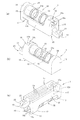
図1から図3のように、実施形態の水準器1は、ケーシング10と、タブ20と、測定表示部としての気泡管30とを有する、いわゆる一軸型の水準器であって、この水準器1を3つ連結することで、器物の側面等、ほぼ鉛直方向を向く測定対象面Sの二次元方向の勾配を測定可能なものとなっている。
Hereinafter, embodiments of the present invention will be described with reference to the drawings.
As shown in FIGS. 1 to 3, the
図1から図3のように、ケーシング10は、矩形の底面11、底面11から左右一対に立ち上がるそれぞれ矩形の側面12、底面11から前後一対に立ち上がるそれぞれ矩形の端面13、およびアーチ形の天面14を有する。ここで、左右一対の側面12および前後一対の端面13が、ケーシング10の周面を構成する。
ケーシング10の寸法は特に限定されないが、たとえば、比較的小型の水準器として、幅が14〜20mm、長さが40〜55mm、高さが17〜23mmであることが例示できる。この程度の大きさであれば、水準器1を複数連結した場合にも、その連結体を手で取り扱いやすい寸法に収まり、また気泡管30として、極端に小さなものではなく視認の容易な寸法のものをケーシング10に搭載することができる。
As shown in FIGS. 1 to 3, the
The dimensions of the
ケーシング10の底面11は、勾配を測定する際の基準面となり、通常は測定対象面Sに当接される。底面11はほぼ平坦に形成されており、その長手方向(一対の端面13間を結ぶ方向)に連続する溝11aが、幅方向に三つ並列して設けられている。
測定対象面Sに微小な凹凸が存在する場合、その凸部が溝11aに入り込むことで凸部と底面11との干渉が防止される。したがって、底面11の溝11aが、勾配測定時における微小な凹凸の影響を排除し、水準器1の測定精度を向上させることができる。
ケーシング10の天面14は、アーチ形に湾曲しており、この天面14から左右の側面12にかけて窓15が設けられている。
また、ケーシング10には、図示省略の磁石が窪みへのはめ込み等の適宜手段により内蔵されている。
ケーシング10の材質は特に限定されないが、合成樹脂製、金属製であることが例示できる。ケーシング10は、たとえば射出成形により形成された左右のケーシング半体同士を嵌合させることにより、作製することができる。
The
When the surface S to be measured has minute irregularities, the convex portions enter the
The
Further, a magnet (not shown) is built in the
The material of the
図1から図3のように、タブ20は、ケーシング10の前後一対の端面13のうち、一方の端面13の下部から突出している。このタブ20の突出方向とケーシング10の長手方向とは、一致している。
タブ20の下面(裏面)とケーシング10の底面11とは、同一平面を構成する。
タブ20の材質は特に限定されないが、合成樹脂製、金属製であることが例示でき、ケーシング10と同じ材質でもよいし、異なる材質でもよい。また、タブ20は、ケーシング10と一体に形成してもよいし、別体に形成したものを連結してもよい。
たとえばタブ20をケーシング10と一体に射出成形することで、水準器1の製造が容易となる。また、タブ20をケーシング10と別体に形成し、そのタブ20を金属製とし、ケーシング10を樹脂製とすることで、水準器1全体の重量増加を防ぎつつ、タブ20の耐摩耗性を向上させることができる。
As shown in FIGS. 1 to 3, the
The lower surface (back surface) of the
The material of the
For example, by injection molding the
タブ20の幅、長さおよび厚みは、ケーシング10の幅(一対の側面間の距離)、長さ(一対の端面間の距離)および高さ(底面と天面間の距離)よりも、充分に小さく、たとえば、幅についてはケーシング10の1/4以上1/2以下、長さについてはケーシング10の1/6以上1/3以下、厚みについてはケーシング10の1/8以上1/4以下となっている。この程度の大きさであれば、タブ20が大きすぎて水準器1全体が大型化することが防がれ、またタブ20が小さすぎて強度が不足したり連結作業に支障をきたしたりすることもない。
また、タブ20の幅は、最先端を除いて、ケーシング10との連結端から先端に向けて漸増しており、最先端においては、タブ20が丸みを帯びることでその幅が急減している。
タブ20は、その厚み方向(表裏面方向)に貫通する円形の係合穴21を二つ有している。係合穴21は、タブ20の突出方向に並列しており、かつその径は、タブ20の先端に近い側の穴がケーシング10との連結端に近い側の穴よりも大きくなっている。
タブ20の下面の先端近傍は、係合穴21と連続する切欠き部22となっている。
The width, length and thickness of the
Further, the width of the
The
The vicinity of the tip of the lower surface of the
図1から図3のように、ケーシング10の前後一対の端面13のうち、タブ20が連設される側の端面13には、第1の凹部16が設けられている。第1の凹部16は、端面13の上部に設けられ、同じ端面13の下部から突出するタブ20とは、上下方向に並列しかつ離間している。
第1の凹部16は、ケーシング10の端面13の中央部から、上方(ケーシング10の底面11から天面14に向かう方向)に延伸して、天面14へと貫通している。天面14への貫通箇所には、矩形の開口14aが形成されており、開口14aの周縁は面取りが施されている。
As shown in FIGS. 1 to 3, among the pair of front and rear end faces 13 of the
The
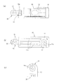
また、ケーシング10の底面11には、第2の凹部17が設けられている。
第2の凹部17は、底面11上において、前記第1の凹部16が設けられた端面13と逆側の端面13に近接し、かつその端面13と平行に延伸して、左右一対の側面12のうち一方の側面12へと貫通している。側面12への貫通箇所には、矩形の開口12aが形成されており、この開口12aの周縁は面取りが施されている。
底面11の溝11aは、第2の凹部17が延伸する箇所には設けられておらず、第2の凹部17と溝11aとは、連通していない。
Further, a
The
The
第1の凹部16の延伸方向、第2の凹部17の延伸方向、およびタブ20の突出方向は、互いに直交している。
第1の凹部16および第2の凹部17は、その窪みの底から突出する円柱形の突起16a、17aをそれぞれ2つ有している。突起16a、17aは、第1の凹部16および第2の凹部17の延伸方向に並列しており、かつその径は、開口12a、14aに近い側の突起が、凹部16,17の開口とは逆側の終端部(突き当り箇所)に近い側の突起よりも小さくなっている。また、突起16a、17aの突出高さと、第1の凹部16および第2の凹部17の窪みの深さとはほぼ等しい、すなわち、第1の凹部16の突起16aの先端部は、端面13と同一平面を構成し、第2の凹部17の突起17aの先端部は、底面11と同一平面を構成する。
第1の凹部16および第2の凹部17は、同形同寸法であって、その幅は、タブ20の幅と等しく、その深さは、タブ20の厚みと等しく、その長さも、タブ20の長さと等しい。また、凹部16、17の突起16a、17aの径は、タブ20の係合穴21の径と等しい。つまり、凹部16、17の形状は、タブ20と凹凸が反転した補完形状となっている。
The stretching direction of the
The
The
このことから、実施形態の水準器1を複数個用意して、一の水準器のタブ20を他の水準器の第1の凹部16または第2の凹部17にはめ込むことで、互いに連結することが可能となっている。補完形状をなすタブ20と凹部16、17とは隙間なくはまり合い、はまり合った状態で、タブ20の下面と、第1の凹部16が形成されたケーシング10の端面13、および第2の凹部17が形成されたケーシング10の底面11とは、同一平面を構成する。
はめ込み作業の際には、開口12a、14aの周縁は面取りされているため、タブ20が開口縁に干渉することが防止されている。また、凹部16、17は、開口12a、14aに向けて幅が狭まっており、タブ20もこれに対応した形状となっているため、タブ20は、(タブ20の係合穴21や凹部16、17の突起16a、17aが存在しない場合でも)開口12a、14aの側に向けて抜き取り不能となっている。
From this, a plurality of
Since the peripheral edges of the
図1から図3のように、測定表示部としての気泡管30は、中空円柱形の管体31と、管体31内に充填された水等の液体32と、液体32内を浮遊する気泡33と、からなる。
気泡管30は、その管体31の軸心がケーシング10の長手方向と一致するように、ケーシング10に保持されている。管体31の軸心とケーシング10の底面11とは、平行になっている。気泡管30は、両端部および下部を除く大部分が、ケーシング10の窓15を通じて露出しており、外部から視認可能となっている。
透明の管体31には、その軸心方向に並列する標線31aが付されている。各標線31aは、管体31の全周にわたって円環形をなしている。標線31aは、ケーシング10の一方の端面13の側に偏って2つが近接して、他方の端面13の側に偏って2つが近接して、計4つが設けられている。
管体31の材質は特に限定されないが、ガラス製、透明の合成樹脂製であることが例示できる。管体31は、たとえば円筒体の両端を円板で閉塞することにより作製することができる。液体32は、気泡33の視認性を高めるために、色付けされていてもよい。
As shown in FIGS. 1 to 3, the
The
A
The material of the
実施形態の水準器1の構成は以上のようであり、いまこれを単体で用いる場合には、そのまま、測定の基準面となるケーシング10の底面11を鉄板等からなる測定対象面Sに当接させる。ケーシング10に内蔵された磁石の作用で、底面11は測定対象面Sに吸着し、水準器1は位置決めされる。
この状態で、気泡管30内の気泡33は、浮力の作用により管体31の軸心に沿って、測定基準面Sの傾斜方向の上流側へと移動する。
管体31に付された標線31aと気泡33との相対的な位置関係を視認することで、測定対象面Sの勾配を確認することができる。
気泡管30内の気泡33が、4つの標線31aのうちの、内側の2つの標線31aの間に位置している場合、測定対象面Sはほぼ勾配が存在しないことを意味する。
また、気泡33が、外側の2つの標線31aよりも管体31の端部寄りに位置している場合、測定対象面Sに大きな勾配があることを意味し、ほぼ標線31a上に位置している場合、測定対象面Sに小さな勾配があることを意味する。
これにより、実施形態の水準器1は、測定対象面Sの一次元方向の勾配を測定可能となっている。
The configuration of the
In this state, the
By visually recognizing the relative positional relationship between the
When the
Further, when the
As a result, the
つぎに、ほぼ水平方向を向く測定対象面の二次元方向の勾配を測定したい場合には、実施形態の水準器1を2つ準備し、その一方の水準器1の第2の凹部17に他方の水準器1のタブ20をはめ込み、両水準器1がその長手方向(気泡管30の軸心方向)が直交するように、平面視でL字型に連結する。
この状態で、2つの水準器1の、測定の基準面となるケーシング10の底面11をともに鉄板等からなる測定対象面Sに当接させ、磁石の作用で位置決めすると、一方の水準器1で測定対象面Sの前後方向の勾配を、他方の水準器1で左右方向の勾配を、同時に測定することができる。
Next, when it is desired to measure the gradient in the two-dimensional direction of the measurement target surface facing almost horizontally, two
In this state, when the
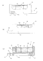
さらに、図4のように、ほぼ鉛直方向を向く測定対象面Sの二次元方向の勾配を測定したい場合には、実施形態の水準器1を3つ準備し、その1つの水準器1の第1の凹部16および第2の凹部17に、他の2つの水準器1のタブ20をはめ込み連結する。
3つの水準器1は、それぞれその長手方向が、上下方向、前後方向および左右方向を向いて、互いに直交した状態に連結される。
こうして連結された水準器1のうち、長手方向が上下方向を向く水準器1のケーシング10の底面11を、測定する際の基準面として鉄板等からなる測定対象面Sに当接させる。磁石の作用により、ほぼ鉛直方向を向く測定対象面Sに対して水準器1が位置決めされるため、この水準器1を手で下から受け支える等する必要はない。
このとき、長手方向が前後方向を向く水準器1や左右方向を向く水準器1は、ほぼ水平な状態に維持されることになる。
長手方向が前後方向を向く水準器1には、測定対象面Sの前後方向の勾配が反映される。また、長手方向が上下方向を向く水準器1の気泡管30の気泡33は、端部に昇り切ってしまうため(図4参照)、測定の用をなさないが、この水準器1と直交して長手方向が左右方向を向く水準器1には、測定対象面Sの上下方向の勾配が反映される。
このため、ほぼ鉛直方向を向く測定対象面の、二次元方向の勾配を同時に測定することが可能となる。
なお、図4では、測定対象面Sは上下前後方向に広がる平面となっているが、測定対象面Sが上下左右方向に広がる平面である場合についても、同様に勾配を測定可能である。この場合、長手方向が左右方向を向く水準器1に、測定対象面Sの左右方向の勾配が反映され、長手方向が前後方向を向く水準器1に、測定対象面Sの上下方向の勾配が反映されることになる。
Further, as shown in FIG. 4, when it is desired to measure the gradient in the two-dimensional direction of the measurement target surface S facing the substantially vertical direction, three
The three
Of the
At this time, the
The
Therefore, it is possible to simultaneously measure the gradient in the two-dimensional direction of the measurement target surface facing the substantially vertical direction.
In FIG. 4, the measurement target surface S is a plane that spreads in the vertical and front-back directions, but the gradient can be measured in the same manner even when the measurement target surface S is a plane that spreads in the vertical and horizontal directions. In this case, the horizontal gradient of the measurement target surface S is reflected in the
測定が終了すると、水準器1の凹部16、17から他の水準器1のタブ20を抜き取って連結を解除する。タブ20の切欠き部22に指先を入れたり、タブ20をその切欠き部22と凹部16、17の底との間に形成される隙間分だけ傾けたりすることで、連結の解除作業は円滑に行われる。
When the measurement is completed, the
タブ20や凹部16、17は、水準器1の長手方向の端部に設けられているため、水準器同士を連結および連結解除する際に、ケーシング10同士が干渉しにくく、連結作業および連結解除作業が円滑におこなわれる。
タブ20や凹部16、17の上記のような位置関係に加えて、気泡管30は水準器1の長手方向の中央部に設けられているため、気泡管30に他の水準器1のケーシング10が重なり合うことが防止されている。このため気泡管30を目視で確認する際に、他の水準器1のケーシング10が邪魔になることはない。
水準器同士を連結する際には、タブ20と凹部16、17とがはまり合うことに加えて、タブ20の係合穴21と凹部16、17の突起16a、17aもはまり合うため、連結強度が大きく、意図せずして連結が解除することが防止されている。
特に、ほぼ鉛直方向を向く測定対象面Sの勾配を測定する場合には、前後方向を向く水準器1と左右方向を向く水準器1は宙に浮いた状態となり、重力の作用により、これらの水準器1に他の水準器1との連結箇所を中心に傾斜しようとする力が負荷される。通常であれば、連結が解除されやすくなるところ、実施形態の水準器1の場合、傾斜しようとする力の負荷により、タブ20の係合穴21の孔の内周に凹部16、17の突起16a、17aの外周が強く押し付けられることになるため、疑似的な締まり嵌め状態となって、連結強度が一層高くなる。
Since the
In addition to the above-mentioned positional relationships of the
When connecting the spirit levels, the
In particular, when measuring the slope of the measurement target surface S that faces almost vertically, the
今回開示された実施形態はすべての点で例示であって制限的なものではない。本発明の範囲は特許請求の範囲によって示され、特許請求の範囲内およびこれと均等の意味でのすべての修正と変形を含む。 The embodiments disclosed this time are exemplary in all respects and are not restrictive. The scope of the present invention is indicated by the scope of claims and includes all modifications and modifications within the scope of claims and in the sense equivalent thereto.
実施形態では、水準器1の測定表示部として気泡管30を例示したが、測定表示部はこれに限定されず、たとえば特許文献1のような指針を用いたものでもよいし、デジタル表示されるものでもよい。
また、測定表示部として気泡管30を用いた水準器と、指針を用いた水準器に、それぞれ凹部16、17やタブ20を設けて両者を連結することも可能である。
In the embodiment, the
Further, it is also possible to provide
タブ20や凹部16、17の形状は、補完形状である限りにおいて実施形態のものに限定されず、たとえばタブ20を先細りの形状としてもよい。
係合穴21や突起16a、17aの形状や数についても実施形態に限定されず、たとえば角柱形、非貫通の半球形でもよく、並列する突起間で形状を違えてもよい。係合穴21や突起16a、17aを省略することもできる。切欠き部22も省略可能である。
タブ20の形成位置、第1の凹部16のケーシングの端面13上における形成位置、および第2の凹部17のケーシング10の底面11上における形成位置も、水準器同士の連結や測定表示部の視認に支障がない限りにおいて、実施形態のものに限定されない。
The shapes of the
The shape and number of the engaging
The formation position of the
ケーシング10の形状も、実施形態に限定されず、平面視で、多角形、円形、楕円形などでもよく、天面をドーム状にしたり、凹状にしたりしてもよい。ケーシング10の底面11の溝11aは省略可能である。
ケーシング10には、第1の凹部16、第2の凹部17以外の凹部が形成されていてもよいし、タブ20以外のタブが設けられていてもよい。たとえば、両端面13に凹部を設けたり、底面11に凹部を複数設けたり、側面12や天面14にも凹部を設けたりしてもよい。
実施形態では、ケーシング10に磁石を内蔵させているが、磁石を省略することも可能である。
The shape of the
The
In the embodiment, the
1 実施形態の水準器
10 ケーシング
11 底面
11a 溝
12 側面
12a 開口
13 端面
14 天面
14a 開口
15 窓
16 第1の凹部
16a 突起
17 第2の凹部
17a 突起
20 タブ
21 係合穴
22 切欠き部
30 気泡管
31 管体
31a 標線
32 液体
33 気泡
S 測定対象面
1
Claims (6)
底面、周面および天面を有して、前記測定表示部を保持し、その底面が前記勾配を測定する際の基準面となるケーシングと、
前記ケーシングの周面から突出し、その下面が前記ケーシングの底面と同一平面をなすタブと、を備え、
前記ケーシングは、
前記周面から前記タブの突出方向に対して垂直な方向に延伸して前記天面へと貫通し、かつ前記タブと補完形状をなす第1の凹部と、
前記底面から前記タブの突出方向および前記第1の凹部の延伸方向のいずれに対しても垂直な方向に延伸して前記周面へと貫通し、かつ前記タブと補完形状をなす第2の凹部と、を有する水準器。 A measurement display unit that can measure and display the gradient of the measurement target surface in one dimension direction,
A casing that has a bottom surface, a peripheral surface, and a top surface, holds the measurement display unit, and the bottom surface serves as a reference surface for measuring the gradient.
A tab that protrudes from the peripheral surface of the casing and whose lower surface is flush with the bottom surface of the casing is provided.
The casing is
A first recess extending from the peripheral surface in a direction perpendicular to the protruding direction of the tab, penetrating the top surface, and forming a complementary shape to the tab.
A second recess that extends from the bottom surface in a direction perpendicular to both the protruding direction of the tab and the stretching direction of the first recess to penetrate the peripheral surface and has a complementary shape to the tab. And a spirit level with.
前記測定表示部は、前記ケーシングの長手方向の中央部に保持されており、
前記タブは、前記ケーシングの長手方向の両端部のうち一端部に位置し、かつ前記ケーシングの長手方向に突出し、
前記第1の凹部は、前記ケーシングの長手方向の両端部のうち一端部であって前記タブの上方に位置し、
前記第2の凹部は、前記ケーシングの長手方向の両端部のうち他端部に位置する請求項1に記載の水準器。 The casing has a longitudinal direction
The measurement display unit is held at the central portion in the longitudinal direction of the casing.
The tab is located at one end of both ends of the casing in the longitudinal direction and projects in the longitudinal direction of the casing.
The first recess is one end of both ends in the longitudinal direction of the casing and is located above the tab.
The level according to claim 1, wherein the second recess is located at the other end of both ends in the longitudinal direction of the casing.
前記タブは、前記突起と補完形状をなす係合穴を有する請求項1または2に記載の水準器。 The first recess and the second recess of the casing have columnar protrusions protruding from the bottom of the recess.
The spirit level according to claim 1 or 2, wherein the tab has an engaging hole forming a complementary shape with the protrusion.
前記タブの係合穴は、前記複数の突起に一対一に対応して補完形状をなすように、形状または寸法の異なるものがタブの突出方向に並列して複数設けられている請求項3に記載の水準器。 A plurality of protrusions of the first recess and the second recess of the casing having different shapes or dimensions in the extending direction of the recess are provided in parallel.
According to claim 3, a plurality of engaging holes having different shapes or dimensions are provided in parallel in the protruding direction of the tab so as to form a complementary shape to the plurality of protrusions in a one-to-one manner. Described level.
中空円柱形で、その軸心が前記ケーシングの底面と平行な管体と、
前記管体に充填された液体と、
前記液体内を浮遊する気泡と、を有する気泡管である、請求項1から4のいずれかに記載の水準器。 The measurement display unit
A tube body that has a hollow cylindrical shape and whose axis is parallel to the bottom surface of the casing.
The liquid filled in the tube and
The level according to any one of claims 1 to 4, which is a bubble tube having a bubble floating in the liquid.
前記ケーシングの底面は、前記測定対象面に対し磁力の作用で吸着可能である、請求項1から5のいずれかに記載の水準器。 Further equipped with a magnet built in the casing
The level according to any one of claims 1 to 5, wherein the bottom surface of the casing can be attracted to the surface to be measured by the action of a magnetic force.
Priority Applications (1)
| Application Number | Priority Date | Filing Date | Title |
|---|---|---|---|
| JP2017114114A JP6830657B2 (en) | 2017-06-09 | 2017-06-09 | Level |
Applications Claiming Priority (1)
| Application Number | Priority Date | Filing Date | Title |
|---|---|---|---|
| JP2017114114A JP6830657B2 (en) | 2017-06-09 | 2017-06-09 | Level |
Publications (2)
| Publication Number | Publication Date |
|---|---|
| JP2018205266A JP2018205266A (en) | 2018-12-27 |
| JP6830657B2 true JP6830657B2 (en) | 2021-02-17 |
Family
ID=64957061
Family Applications (1)
| Application Number | Title | Priority Date | Filing Date |
|---|---|---|---|
| JP2017114114A Active JP6830657B2 (en) | 2017-06-09 | 2017-06-09 | Level |
Country Status (1)
| Country | Link |
|---|---|
| JP (1) | JP6830657B2 (en) |
-
2017
- 2017-06-09 JP JP2017114114A patent/JP6830657B2/en active Active
Also Published As
| Publication number | Publication date |
|---|---|
| JP2018205266A (en) | 2018-12-27 |
Similar Documents
| Publication | Publication Date | Title |
|---|---|---|
| CN1942737B (en) | Concealed Column Tubes for Spirit Levels | |
| AU2005236453B2 (en) | Structure and method for holding and protecting vials in levels | |
| JP6830657B2 (en) | Level | |
| KR101537573B1 (en) | A multifunction drafting instrument | |
| JP5792408B1 (en) | Level | |
| JP2006153555A (en) | Tread radius measuring jig | |
| JP2015205714A (en) | Weighing cap and container | |
| KR200334251Y1 (en) | Green slant measuring instrument of golf course | |
| CN103175511B (en) | Utilize the spirit level of floating body | |
| JP2021148449A (en) | Dimension measuring jig | |
| JP2012202849A (en) | Inclination measuring device and inclination measuring method | |
| JP3845097B2 (en) | Box detector | |
| KR200463225Y1 (en) | Apparatus for measuring strike and dip | |
| JP7849874B2 (en) | Bubble tube and spirit level | |
| JP6792290B2 (en) | Injury gauge | |
| KR101227684B1 (en) | Plane-table for cadastral surveying | |
| KR101391791B1 (en) | Vertical care device for pile construction | |
| KR20190000006U (en) | A target for measure the displacement in tunnel | |
| JP2017129405A (en) | Level | |
| KR20080071677A (en) | Block gauge | |
| KR101642688B1 (en) | clinometer for golf | |
| KR20250121505A (en) | a ruler which can mark | |
| JP2015068719A (en) | Liquid level indicator | |
| CN210464351U (en) | Flatness detection device for building engineering | |
| JP3195807U (en) | Golf marker |
Legal Events
| Date | Code | Title | Description |
|---|---|---|---|
| A621 | Written request for application examination |
Free format text: JAPANESE INTERMEDIATE CODE: A621 Effective date: 20200127 |
|
| A977 | Report on retrieval |
Free format text: JAPANESE INTERMEDIATE CODE: A971007 Effective date: 20201119 |
|
| TRDD | Decision of grant or rejection written | ||
| A01 | Written decision to grant a patent or to grant a registration (utility model) |
Free format text: JAPANESE INTERMEDIATE CODE: A01 Effective date: 20201215 |
|
| A61 | First payment of annual fees (during grant procedure) |
Free format text: JAPANESE INTERMEDIATE CODE: A61 Effective date: 20210113 |
|
| R150 | Certificate of patent or registration of utility model |
Ref document number: 6830657 Country of ref document: JP Free format text: JAPANESE INTERMEDIATE CODE: R150 |
|
| R250 | Receipt of annual fees |
Free format text: JAPANESE INTERMEDIATE CODE: R250 |
|
| R250 | Receipt of annual fees |
Free format text: JAPANESE INTERMEDIATE CODE: R250 |
|
| R250 | Receipt of annual fees |
Free format text: JAPANESE INTERMEDIATE CODE: R250 |