JP6830688B1 - Road cone - Google Patents
Road cone Download PDFInfo
- Publication number
- JP6830688B1 JP6830688B1 JP2019198562A JP2019198562A JP6830688B1 JP 6830688 B1 JP6830688 B1 JP 6830688B1 JP 2019198562 A JP2019198562 A JP 2019198562A JP 2019198562 A JP2019198562 A JP 2019198562A JP 6830688 B1 JP6830688 B1 JP 6830688B1
- Authority
- JP
- Japan
- Prior art keywords
- cone
- road
- main body
- holes
- cones
- Prior art date
- Legal status (The legal status is an assumption and is not a legal conclusion. Google has not performed a legal analysis and makes no representation as to the accuracy of the status listed.)
- Active
Links
Images


Landscapes
- Refuge Islands, Traffic Blockers, Or Guard Fence (AREA)
Abstract
【課題】容易にかつ確実に、柵を所望の位置に設置可能としたロードコーンを提供する。【解決手段】中空錐体状の本体部11と、本体部11の錐体面にその内外を貫通するように周方向に沿って形成された複数の錐体貫通孔12と、を有するロードコーンを構成する。【選択図】図1PROBLEM TO BE SOLVED: To provide a road cone in which a fence can be easily and surely installed at a desired position. SOLUTION: A road cone having a hollow cone-shaped main body portion 11 and a plurality of cone through holes 12 formed along the circumferential direction on the cone surface of the main body portion 11 so as to penetrate the inside and outside thereof. Configure. [Selection diagram] Fig. 1
Description
この発明は、道路やイベント会場等に配置され、交通規制や人の流れを誘導するための柵を形成するのに用いられるロードコーンに関する。 The present invention relates to a road cone that is placed on a road, an event venue, or the like and is used for forming a fence for guiding traffic regulation and the flow of people.
例えば、下記特許文献1に示すように、ロードコーン(交通整理用コーン1)として、円錐形状の本体部2とベース部3を一体としたものが公知となっている(特許文献1の段落0013、図1等参照)。このロードコーンの使用態様の一例として、複数のロードコーンを互いに所定間隔をあけて地面に配置し、隣り合うロードコーンの頂部に掛け渡すように、この頂部に嵌まるリングが両端に取り付けられた所定長さの棒状部材を設けたり、この頂部にロープを巻き付けたりすることによって柵を形成することがある。この柵によって、交通規制やイベント会場等における人の流れの誘導を行っている。 For example, as shown in Patent Document 1 below, a road cone (traffic control cone 1) in which a conical body portion 2 and a base portion 3 are integrated is known (paragraph 0013 of Patent Document 1). , See Fig. 1 etc.). As an example of the usage of this road cone, a plurality of road cones are placed on the ground at a predetermined distance from each other, and rings fitted to the tops of the adjacent road cones are attached to both ends so as to hang over the tops of the adjacent road cones. A fence may be formed by providing a rod-shaped member having a predetermined length or wrapping a rope around the top of the rod-shaped member. This fence guides the flow of people at traffic regulations and event venues.
特許文献1に示すロードコーンで柵を形成する場合、ロードコーンのための専用品である予め決められた長さの棒状部材を使用しなければならず、隣り合うロードコーンの間隔が決まってしまう。このため、例えば複数のロードコーンを用いて柵を形成する場合に、その柵の設置の自由度が制限される問題がある。また、ロードコーンの頂部にロープを巻き付ける場合は、隣り合うロードコーンの間隔を自由に決めることができるものの、時間の経過や人がロープに触れることによってロープが弛んでしまい、柵としての機能が発揮できなくなる問題がある。 When forming a fence with the road cones shown in Patent Document 1, it is necessary to use a rod-shaped member having a predetermined length, which is a special product for the road cones, and the distance between adjacent road cones is determined. .. Therefore, for example, when a fence is formed by using a plurality of road cones, there is a problem that the degree of freedom in installing the fence is limited. Also, when wrapping a rope around the top of a road cone, the distance between adjacent road cones can be freely determined, but the rope will loosen over time or when a person touches the rope, and it will function as a fence. There is a problem that it cannot be demonstrated.
そこで、この発明は、ロードコーンを用いて容易にかつ確実に、柵を所望の位置に設置可能とすることを課題とする。 Therefore, an object of the present invention is to make it possible to easily and surely install a fence at a desired position by using a road cone.
上記の課題を解決するため、この発明は、中空錐体状の本体部と、前記本体部の錐体面にその内外を貫通するように周方向に沿って形成された複数の錐体貫通孔と、を有するロードコーンを構成した。 In order to solve the above-mentioned problems, the present invention comprises a hollow cone-shaped main body portion and a plurality of cone through holes formed along the circumferential direction on the cone surface of the main body portion so as to penetrate the inside and outside thereof. A road cone with, was constructed.
このようにすると、本体部の錐体面に形成された錐体貫通孔に所望の長さの棒状部材を挿し込む、又は、錐体貫通孔にロープを括り付けることによって、容易にかつ確実に、柵を所望の位置に設置することができる。 In this way, a rod-shaped member having a desired length is inserted into the cone through hole formed on the cone surface of the main body, or a rope is tied to the cone through hole to easily and surely. The fence can be installed at the desired position.
前記構成においては、前記本体部の頂部に、該本体部を垂直方向に貫通する頂部貫通孔をさらに有する構成とすることができる。 In the above configuration, the top of the main body may be further provided with a top through hole that vertically penetrates the main body.
このようにすると、頂部貫通孔に垂直棒を挿入し、隣り合って配置された垂直棒同士の間に表示部材を設けたり、この垂直棒の上端部に旗を設けたりすることができる。このようにして設けられた表示部材や旗は、ロードコーンの上端よりもさらに高いところに位置しているので、表示部材や旗の高い視認性を確保することができる。 In this way, a vertical bar can be inserted into the top through hole to provide a display member between the vertically arranged vertical bars, or a flag can be provided at the upper end of the vertical bar. Since the display member and the flag provided in this way are located higher than the upper end of the road cone, high visibility of the display member and the flag can be ensured.
前記各構成においては、前記錐体貫通孔が、前記本体部の上下方向の高さが異なる複数の高さ方向位置に形成されており、かつ、各高さ方向位置に形成された前記錐体貫通孔が、いずれも異なる周方向位置にある構成とすることができる。 In each of the above configurations, the cone through holes are formed at a plurality of height direction positions where the heights of the main body portion in the vertical direction are different, and the cones are formed at the respective height direction positions. The through holes can be configured to be located at different circumferential positions.
このようにすると、同一高さに多く(例えば8個等)の錐体貫通孔を形成することに起因して、本体部の上部の剛性が低下するのを防止しつつ、本体部への棒状部材やロープの接続方向の選択性の向上を図ることができる。 In this way, the rod shape to the main body portion is prevented from being lowered in the rigidity of the upper portion of the main body portion due to the formation of many cone through holes (for example, eight) at the same height. It is possible to improve the selectivity of the connection direction of the member and the rope.
前記各構成においては、前記錐体面が、円錐面、又は、多角錐面である構成とすることができる。 In each of the above configurations, the pyramid surface may be a conical surface or a polygonal pyramid surface.
このようにすると、錐体面が円錐面のロードコーンを通常用いる一方で、ロードコーンの本体部に文字や記号を記載する必要があるときは、錐体面を多角錐面としてその文字や記号を読みやすくする等の使い分けをすることができる。 In this way, while a traffic cone with a conical pyramid surface is usually used, when it is necessary to write a character or symbol on the main body of the road cone, the character or symbol is read with the pyramid surface as a polygonal pyramid surface. It can be used properly, such as making it easier.
この発明においては、中空錐体状の本体部と、前記本体部の錐体面にその内外を貫通するように周方向に沿って形成された複数の錐体貫通孔と、を有するロードコーンを構成したので、このロードコーンを用いて容易にかつ確実に、柵を所望の位置に設置することができる。 In the present invention, a traffic cone having a hollow cone-shaped main body portion and a plurality of cone through holes formed along the circumferential direction so as to penetrate the inside and outside of the cone surface of the main body portion is configured. Therefore, the fence can be easily and surely installed at a desired position by using this road cone.
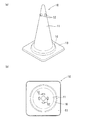
この発明に係るロードコーン10の第一参考実施形態を図1(a)(b)に示す。このロードコーン10は、中空錐体状の本体部11と、本体部11の錐体面にその内外を貫通するように周方向に沿って形成された複数の錐体貫通孔12と、を主要な構成要素としている。
The first reference embodiment of the
この実施形態に係るロードコーン10の本体部11は円錐面を有している。この本体部11の下端部には、フランジ13が一体に形成されている。本体部11及びフランジ13の素材として、ポリ塩化ビニル(PVC)やポリエチレン(PE)等の樹脂が用いられるが、寒冷地等のように過酷な環境下における耐候性を向上するために、エチレン酢酸ビニルコポリマー(EVA)等を用いることもできる。
The
錐体貫通孔12は、本体部11の上部近傍に、周方向に90度間隔で4個形成されている。錐体貫通孔12の形成位置や数は特に限定されず、例えば、120度間隔で3個形成する、あるいは、60度間隔で6個形成するなどとしてもよい。錐体貫通孔12の直径は特に限定されないが、後述するように、この錐体貫通孔12への棒状部材14の挿入やロープ15の括り付けを容易に行うために、2〜5cm程度とするのが好ましい。また、錐体貫通孔12の形状は円形に限定されず、楕円形状や多角形状とすることもできる。また、上記のように周方向の角度間隔を同一とせずに、異なる角度間隔で(例えば、60度と120度を交互に)形成することもできる。
Four cone through
フランジ13には、着脱式の環状の錘16が設けられており、この錘16の荷重によって、強風や人との接触によってロードコーン10が不用意に移動したり倒れたりするのを防止している。錘16の素材として、ゴムを用いるのが一般的であるが、他の素材を用いることもできる。
A detachable
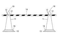
図1(a)(b)に示すロードコーン10の使用態様を図2に示す。まず、複数のロードコーン10を互いに所定間隔をあけて地面に配置する。そして、隣り合うそれぞれのロードコーン10に形成された錐体貫通孔12に棒状部材14を挿入する。隣り合うロードコーン10の間のすべてに棒状部材14を挿入することによって、柵が連続的に形成される。この棒状部材14は、ロードコーン10に使用するための専用品ではないため入手が容易である。また、必要に応じて切断した上で使用することも可能である。このため、隣り合うロードコーン10の間隔を適宜決めることができ、このロードコーン10を用いて、容易にかつ確実に、柵を所望の位置に設置することができる。
The usage mode of the
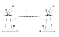
図1(a)(b)に示すロードコーン10の他の使用態様を図3に示す。まず、複数のロードコーン10を互いに所定間隔をあけて地面に配置する。そして、隣り合うそれぞれのロードコーン10に形成された錐体貫通孔12にロープ15を括り付ける。隣り合うロードコーン10の間のすべてにロープ15を括り付けることによって、柵が連続的に形成される。このロープ15の長さを調節することにより、隣り合うロードコーン10の間隔を適宜決めることができ、このロードコーン10を用いて、容易にかつ確実に、柵を所望の位置に設置することができる。しかも、ロープ15は錐体貫通孔12にしっかりと括り付けられているため、時間の経過や人がロープに触れることによる緩みが生じにくい。このため、柵としての機能を長時間に亘って維持することができる。
Another usage mode of the
この発明に係るロードコーン10の第二参考実施形態を図4(a)(b)に示す。このロードコーン10は、第一参考実施形態に係るロードコーン10(図1参照)に対し、本体部11の頂部に、この本体部11を垂直方向に貫通する頂部貫通孔17をさらに形成したものである。
A second reference embodiment of the
頂部貫通孔17の直径は特に限定されないが、後述する垂直棒18を容易に挿入しつつガタつきなく保持するために、2〜5cm程度とするのが好ましい。この頂部貫通孔17に挿入する垂直棒18の直径が決まっているのであれば、その直径に対応して、頂部貫通孔17の直径を決めるのが好ましい。
The diameter of the top through
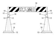
図4(a)(b)に示すロードコーン10の使用態様を図5に示す。まず、2個のロードコーン10を互いに所定間隔をあけて地面に配置する。そして、隣り合うそれぞれのロードコーン10に形成された頂部貫通孔17に垂直棒18をそれぞれ挿入する。両垂直棒18の間には、例えば「立入禁止」等と記載された表示部材19が掛け渡される。このようにすると、この表示部材19によって柵を容易に形成することができる。しかも、表示部材19は、ロードコーン10の頂部貫通孔17に挿入された垂直棒18に取り付けられているため、このロードコーン10の上端よりもさらに高いところに位置している。このため、表示部材19の高い視認性を確保することもできる。
FIG. 5 shows a usage mode of the
なお、図5には図示していないが、2個のロードコーン10の両端にさらにロードコーン10を配置し、隣り合うロードコーン10の間に棒状部材14(図2参照)を挿入する等して、柵をさらに延長することもできる。
Although not shown in FIG. 5,
図4(a)(b)に示すロードコーン10の他の使用態様を図6に示す。まず、2個のロードコーン10を互いに所定間隔をあけて地面に配置する。そして、隣り合うそれぞれのロードコーン10に形成された錐体貫通孔12に水平棒20を挿入する。水平棒20には、例えば「立入禁止」等と記載された表示部材19が吊り下げられる。さらに、一方のロードコーン10の頂部貫通孔17には垂直棒18が挿入され、その垂直棒18の上端部に旗21が取り付けられる。このようにすると、表示部材19が吊り下げられた水平棒20によって柵を容易に形成することができる。しかも、旗21は、ロードコーン10の頂部貫通孔17に挿入された垂直棒18に取り付けられているため、このロードコーン10の上端よりもさらに高いところに位置しており視認性が高い。このため、この旗21によって、その位置に柵が設けられていることについて注意喚起することができる。
6 shows another usage mode of the
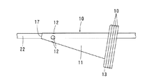
図4(a)(b)に示すロードコーン10は、図7に示すように、その使用後に複数個を重ねた状態とし、頂部貫通孔17に棒状の持ち運び用治具22を挿入し、この持ち運び用治具22の両端をそれぞれ別の作業員が保持することによって、容易にまとめて持ち運ぶことができる。このため、道路工事やイベント等の終了後におけるロードコーン10の片付けをスムーズに行うことができる。
As shown in FIGS. 7, the
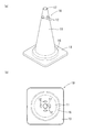
この発明に係るロードコーン10の一実施形態を図8(a)(b)に示す。このロードコーン10は、第一参考実施形態に係るロードコーン10(図1参照)と異なり、錐体貫通孔12、23が、本体部11の上下方向の高さが異なる複数の高さ方向位置に形成されており、かつ、各高さ方向位置に形成された錐体貫通孔12、23が、いずれも異なる周方向位置にある。具体的には、本体部11の上部近傍に、錐体貫通孔12を周方向に90度間隔で4個形成するとともに、この錐体貫通孔12の形成位置よりも下側かつ周方向に45度ずれた位置に、錐体貫通孔23を周方向に90度間隔で4個形成している。
One embodiment of the
このようにすると、同一高さに多く(例えば8個等)の錐体貫通孔12を形成することに起因して、本体部11の上部の剛性が低下するのを防止しつつ、本体部11への棒状部材14やロープ15の接続方向の選択性の向上を図ることができる。
In this way, the rigidity of the upper portion of the
この発明に係るロードコーン10の第三参考実施形態を図9(a)(b)に示す。このロードコーン10は、第一参考実施形態等に係るロードコーン10の本体部11が円錐面を有するのに対し、この本体部11が四角錐面を有する構成としたものである。このように、本体部11が四角錐面を有すると、この本体部11(四角錐面)に文字や記号(例えば、イベント会場の方向を示す矢印)を記載したときに、円錐面に記載したときよりも、その文字や記号を読みやすいというメリットがある。なお、本実施形態においては、本体部11に四角錐面を採用したが、三角錐面や六角錐面等とすることもできる。また、本体部11の頂部の頂部貫通孔17を省略した構成とすることもできる。
A third reference embodiment of the
上記の各実施形態はあくまでも例示であって、ロードコーン10を用いて容易にかつ確実に、柵を所望の位置に設置可能とする、というこの発明の課題を解決し得る限りにおいて、その構成を適宜変更することができる。上記の各実施形態で示した構成はそれぞれ組み合わせることもでき、例えば、本体部11が四角錐面を有する構成(図9(a)(b)参照)に対し、錐体貫通孔12、23が、本体部11の上下方向の高さが異なる複数の高さ方向位置に形成された構成(図8(a)(b)参照)を適用することもできる。
Each of the above embodiments is merely an example, and the configuration thereof is provided as long as the problem of the present invention that the fence can be easily and surely installed at a desired position by using the
10 ロードコーン
11 本体部
12、23 錐体貫通孔
13 フランジ
14 棒状部材
15 ロープ
16 錘
17 頂部貫通孔
18 垂直棒
19 表示部材
20 水平棒
21 旗
22 持ち運び用治具
10
Claims (3)
前記本体部(11)の上部近傍の錐体面にその内外を貫通するように周方向に沿って形成された複数の錐体貫通孔(12、23)と、
を有し、
前記錐体貫通孔(12)が周方向に90度間隔で4個形成されるとともに、この錐体貫通孔(12)の形成位置よりも下側かつ周方向に45度ずれた位置に、前記錐体貫通孔(23)が周方向に90度間隔で4個形成されたロードコーン。 Hollow cone-shaped body (11) and
A plurality of cone through holes (12, 23) formed along the circumferential direction on the cone surface near the upper portion of the main body (11) so as to penetrate the inside and outside thereof.
Have,
Four cone through holes (12) are formed at intervals of 90 degrees in the circumferential direction, and at a position below the formation position of the cone through holes (12) and displaced by 45 degrees in the circumferential direction. A road cone in which four cone through holes (23) are formed at intervals of 90 degrees in the circumferential direction .
Priority Applications (1)
| Application Number | Priority Date | Filing Date | Title |
|---|---|---|---|
| JP2019198562A JP6830688B1 (en) | 2019-10-31 | 2019-10-31 | Road cone |
Applications Claiming Priority (1)
| Application Number | Priority Date | Filing Date | Title |
|---|---|---|---|
| JP2019198562A JP6830688B1 (en) | 2019-10-31 | 2019-10-31 | Road cone |
Publications (2)
| Publication Number | Publication Date |
|---|---|
| JP6830688B1 true JP6830688B1 (en) | 2021-02-17 |
| JP2021070980A JP2021070980A (en) | 2021-05-06 |
Family
ID=74562367
Family Applications (1)
| Application Number | Title | Priority Date | Filing Date |
|---|---|---|---|
| JP2019198562A Active JP6830688B1 (en) | 2019-10-31 | 2019-10-31 | Road cone |
Country Status (1)
| Country | Link |
|---|---|
| JP (1) | JP6830688B1 (en) |
Cited By (2)
| Publication number | Priority date | Publication date | Assignee | Title |
|---|---|---|---|---|
| CN114319183A (en) * | 2022-01-25 | 2022-04-12 | 杜逢春 | Obstacle early warning inspection robot based on big data |
| JP2022168705A (en) * | 2021-04-26 | 2022-11-08 | 株式会社ユニチカテクノス | Manufacturing method for road cone body |
Families Citing this family (2)
| Publication number | Priority date | Publication date | Assignee | Title |
|---|---|---|---|---|
| WO2025009083A1 (en) * | 2023-07-05 | 2025-01-09 | 株式会社カーボーイ | Safety-notice cone |
| JP7829964B1 (en) * | 2025-06-04 | 2026-03-16 | 株式会社トップ | Sheet body erection structure and sheet body |
Family Cites Families (8)
| Publication number | Priority date | Publication date | Assignee | Title |
|---|---|---|---|---|
| JPH0447212Y2 (en) * | 1986-10-29 | 1992-11-09 | ||
| JPS6445882U (en) * | 1987-09-14 | 1989-03-20 | ||
| JPH0223011U (en) * | 1988-07-29 | 1990-02-15 | ||
| JP2003306912A (en) * | 2002-04-15 | 2003-10-31 | Isao Kumada | Color cone and cone bar |
| JP2004003273A (en) * | 2002-04-24 | 2004-01-08 | Kazuhiko Kitagawa | Rod member support, barricade mounting body, barricade structure, boundary indicator, and boundary indicator structure |
| US20040060499A1 (en) * | 2002-09-26 | 2004-04-01 | Penque Frank P. | Portable barricade system |
| JP3125360U (en) * | 2006-07-05 | 2006-09-14 | 安全興業株式会社 | Road construction cone and its connection bar |
| JP3222831U (en) * | 2019-06-17 | 2019-08-29 | 長崎 守高 | Road cone with hook handle on top |
-
2019
- 2019-10-31 JP JP2019198562A patent/JP6830688B1/en active Active
Cited By (4)
| Publication number | Priority date | Publication date | Assignee | Title |
|---|---|---|---|---|
| JP2022168705A (en) * | 2021-04-26 | 2022-11-08 | 株式会社ユニチカテクノス | Manufacturing method for road cone body |
| JP7673953B2 (en) | 2021-04-26 | 2025-05-09 | 株式会社ユニチカテクノス | Manufacturing method of road cone body |
| CN114319183A (en) * | 2022-01-25 | 2022-04-12 | 杜逢春 | Obstacle early warning inspection robot based on big data |
| CN114319183B (en) * | 2022-01-25 | 2023-07-07 | 润咖(上海)智能科技有限公司 | Obstacle early warning inspection robot based on big data |
Also Published As
| Publication number | Publication date |
|---|---|
| JP2021070980A (en) | 2021-05-06 |
Similar Documents
| Publication | Publication Date | Title |
|---|---|---|
| JP6830688B1 (en) | Road cone | |
| JP5037568B2 (en) | Turf protection mat | |
| US9447599B1 (en) | Support pole with a prefabricated engaging thread and method of using the same | |
| JP2018153180A (en) | Lawn protection mat for soft ground and its construction method | |
| US4147320A (en) | Pot hanger | |
| US6216886B1 (en) | Post-mounted hanging device | |
| JP2011062084A (en) | Snake climbing-preventing device | |
| US2635857A (en) | Cement fence post | |
| US5904258A (en) | Balloon centerpiece template | |
| KR101148084B1 (en) | Play net for children which having joy of levitation using by tensile | |
| JPH0447212Y2 (en) | ||
| JP2011120590A (en) | Supporting device of wire material and covering material, supporting device mounting post, and stretching material for the covering material | |
| CN210869237U (en) | Ecological breeding livestock enclosure | |
| JP3171166U (en) | Banner support structure | |
| JP6764014B1 (en) | Road cone | |
| JP2023055131A (en) | Plant-protective umbrella, plant-protective umbrella set, and protector set | |
| JP5962936B1 (en) | How to set up a support for a net | |
| CN105075933A (en) | A reef body having a position change function | |
| JP3221549U (en) | Airborne set-up flag posting device | |
| RU146135U1 (en) | DEVICE FOR SUSPENSION AND LIFTING OF PLANTS | |
| JP3206921U (en) | Pillar support piles such as fruit trees | |
| JP5230570B2 (en) | Snake climbing prevention device | |
| JP3219753U (en) | Banner | |
| JP4208059B2 (en) | Artificial reef | |
| JP3047161U (en) | Indicator for indoor electrical work |
Legal Events
| Date | Code | Title | Description |
|---|---|---|---|
| A621 | Written request for application examination |
Free format text: JAPANESE INTERMEDIATE CODE: A621 Effective date: 20200305 |
|
| A871 | Explanation of circumstances concerning accelerated examination |
Free format text: JAPANESE INTERMEDIATE CODE: A871 Effective date: 20200305 |
|
| A975 | Report on accelerated examination |
Free format text: JAPANESE INTERMEDIATE CODE: A971005 Effective date: 20200311 |
|
| A131 | Notification of reasons for refusal |
Free format text: JAPANESE INTERMEDIATE CODE: A131 Effective date: 20200609 |
|
| A521 | Request for written amendment filed |
Free format text: JAPANESE INTERMEDIATE CODE: A523 Effective date: 20200708 |
|
| A131 | Notification of reasons for refusal |
Free format text: JAPANESE INTERMEDIATE CODE: A131 Effective date: 20200908 |
|
| A521 | Request for written amendment filed |
Free format text: JAPANESE INTERMEDIATE CODE: A523 Effective date: 20201027 |
|
| TRDD | Decision of grant or rejection written | ||
| A01 | Written decision to grant a patent or to grant a registration (utility model) |
Free format text: JAPANESE INTERMEDIATE CODE: A01 Effective date: 20201215 |
|
| A61 | First payment of annual fees (during grant procedure) |
Free format text: JAPANESE INTERMEDIATE CODE: A61 Effective date: 20210113 |
|
| R150 | Certificate of patent or registration of utility model |
Ref document number: 6830688 Country of ref document: JP Free format text: JAPANESE INTERMEDIATE CODE: R150 |
|
| R250 | Receipt of annual fees |
Free format text: JAPANESE INTERMEDIATE CODE: R250 |
|
| R250 | Receipt of annual fees |
Free format text: JAPANESE INTERMEDIATE CODE: R250 |
|
| R250 | Receipt of annual fees |
Free format text: JAPANESE INTERMEDIATE CODE: R250 |