JP6850008B2 - Shift knob cover - Google Patents
Shift knob cover Download PDFInfo
- Publication number
- JP6850008B2 JP6850008B2 JP2018089418A JP2018089418A JP6850008B2 JP 6850008 B2 JP6850008 B2 JP 6850008B2 JP 2018089418 A JP2018089418 A JP 2018089418A JP 2018089418 A JP2018089418 A JP 2018089418A JP 6850008 B2 JP6850008 B2 JP 6850008B2
- Authority
- JP
- Japan
- Prior art keywords
- shift knob
- cover body
- slide fastener
- cover
- notch
- Prior art date
- Legal status (The legal status is an assumption and is not a legal conclusion. Google has not performed a legal analysis and makes no representation as to the accuracy of the status listed.)
- Active
Links
Images


Landscapes
- Arrangement Or Mounting Of Control Devices For Change-Speed Gearing (AREA)
- Mechanical Control Devices (AREA)
Description
本発明は、車両のシフトノブに脱着可能に取り付けられるシフトノブカバーに関するものである。 The present invention relates to a shift knob cover that is detachably attached to a shift knob of a vehicle.
従来、例えば下記の非特許文献1に記載されたシフトノブカバーが知られている。 Conventionally, for example, the shift knob cover described in Non-Patent Document 1 below is known.
この従来のシフトノブカバーは、黒色の天然皮革(本皮)に赤色のステッチを施して構成したものであり、これを車両のシフトノブに取り付ける場合には、付属の針と紐(縫い糸)を用いて靴紐を編むように締め上げる。 This conventional shift knob cover is constructed by applying red stitching to black natural leather (genuine leather), and when attaching this to the shift knob of a vehicle, use the attached needle and string (sewing thread). Tighten like knitting shoelaces.
しかしながら、例えば針を使って縫うことに慣れていない者にとっては、上記従来のシフトノブカバーを縫い付ける取付作業は容易ではなく、その取付作業に手間取るおそれがある。 However, for example, for a person who is not accustomed to sewing with a needle, the mounting work for sewing the conventional shift knob cover is not easy, and the mounting work may take time.
本発明は、このような点に鑑みなされたもので、車両のシフトノブに容易に取り付けることができるシフトノブカバーを提供することを目的とする。 The present invention has been made in view of such a point, and an object of the present invention is to provide a shift knob cover that can be easily attached to a shift knob of a vehicle.
本発明に係るシフトノブカバーは、車両のシフトノブに脱着可能に取り付けられるシフトノブカバーであって、前記シフトノブを覆う袋形状のカバー本体と、前記カバー本体の前側に設けられ、前記カバー本体を前記シフトノブに取り付けるための上下方向長手状のスライドファスナーとを備え、前記カバー本体は、前記スライドファスナーの上方側であって前記カバー本体の前側上部に位置し、前記車両の運転者である操作者が前記シフトノブを把持して操作する際に指を当てる指当て部を有するものである。 Shift Knob cover according to the present invention is a shift knob cover attached removably to the shift knob of the vehicle, and the cover body of the bag shape covering the shift knob, provided on the front side of the cover body, the cover body to the shift knob The cover body is provided with a vertically longitudinal slide fastener for attachment, and the cover body is located on the upper side of the cover body on the front side of the cover body, and an operator who is a driver of the vehicle can use the shift knob. It has a finger rest portion to which a finger is put on when gripping and operating the .
また、本発明に係るシフトノブカバーは、車両のシフトノブに脱着可能に取り付けられるシフトノブカバーであって、前記シフトノブを覆う袋形状のカバー本体と、前記カバー本体の前側に設けられ、前記カバー本体を前記シフトノブに取り付けるための上下方向長手状のスライドファスナーとを備え、前記カバー本体は、前記スライドファスナーの閉状態時に円形状をなす下面開口部と、前記カバー本体の前側において前記下面開口部から上方へ切り欠かれた上下方向長手状の切欠部と、前記スライドファスナーの上方側であって前記カバー本体の前側上部に位置し、前記車両の運転者である操作者が前記シフトノブを把持して操作する際に指を当てる指当て部とを有し、前記スライドファスナーは、前記カバー本体のうち前記切欠部に臨んだ部分に取り付けられた上下方向長手状の左右のテープと、前記各テープの互いに対向する対向縁部にそれぞれ固着されたエレメントと、下方への移動によって前記両エレメントを互いに噛み合わせるとともに、上方への移動によって前記両エレメントを互いに離すスライダーと、前記各テープの下端部に取り付けられ、前記スライダーの下方への移動を規制する下止とを有するものである。Further, the shift knob cover according to the present invention is a shift knob cover that is detachably attached to a shift knob of a vehicle, and is provided with a bag-shaped cover main body that covers the shift knob and a front side of the cover main body, and the cover main body is the said. It is provided with a vertically longitudinal slide fastener for attaching to the shift knob, and the cover body has a lower surface opening that forms a circular shape when the slide fastener is closed, and an upper surface opening on the front side of the cover body. It is located on the notched vertical notch and the upper part of the front side of the cover body on the upper side of the slide fastener, and the operator who is the driver of the vehicle grips and operates the shift knob. The slide fastener has a finger rest portion to which a finger is put on, and the slide fastener is opposed to each other by vertically longitudinal left and right tapes attached to a portion of the cover body facing the notch portion. An element fixed to each of the opposing edges, a slider that engages the two elements with each other by moving downward, and a slider that separates the two elements from each other by moving upward, and a slider attached to the lower end of each tape. It has a lower stop that regulates the downward movement of the slider.
本発明によれば、車両のシフトノブに容易に取り付けることができる。 According to the present invention, it can be easily attached to the shift knob of a vehicle.
本発明の一実施の形態について図面を参照して説明する。 An embodiment of the present invention will be described with reference to the drawings.
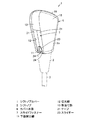
図1ないし図3において、1はシフトノブカバーで、このシフトノブカバー1は、車両である自動車のシフトノブ2に後付けにより脱着可能に取り付けられるものである。
In FIGS. 1 to 3, reference numeral 1 denotes a shift knob cover, and the shift knob cover 1 is detachably attached to a
なお、シフトノブ2は、自動車のトランスミッションに接続された丸棒状のシフトレバー3の先端部(上端部)に取り付けられた取手であり、操作者が把持し易い形状、すなわち例えば略逆円錐形状に形成されている。
The
シフトノブカバー(車両シフトノブ用のカバー)1は、シフトノブ2に脱着可能に取り付けられてこのシフトノブ2を覆う袋形状のカバー本体6と、このカバー本体6の前側における上端側部分を除く部分に設けられ、当該カバー本体6をシフトノブ2に脱着可能に取り付けるための上下方向長手状の開閉可能なスライドファスナー(線ファスナー)7とを備えている。
The shift knob cover (cover for the vehicle shift knob) 1 is provided on a bag-
カバー本体6は、可撓性を有するシート状の素材(例えば天然皮革や合成皮革等の皮革)によって、シフトノブ2の把持部2aの形状に対応する袋形状(把持部2aの外面全体に略密着する袋形状)に形成されている。
The
このカバー本体6は、円形状(略円形状を含む)の下面開口部11と、この下面開口部11から上方へ切り欠かれた上下方向長手状で矩形状の切欠部12と、この切欠部12の上方側に位置する上下方向長手状で矩形状の指当て部13とを有し、この指当て部13は、切欠部12と同じ幅でその切欠部12よりも短い矩形状に形成されている。
The
また、カバー本体6は、シフトノブ2の把持部2aの周側面のうち、上下に並ぶ指当て部13及びスライドファスナー(ファスナー部)によって覆われる部分以外の部分を覆う周側面カバー部15と、シフトノブ2の把持部2aの上面を覆う上面カバー部16とを有している。
Further, the
つまり、シフトノブ2の把持部2aの周側面は、カバー本体6の周側面カバー部15及び指当て部13と閉状態のスライドファスナー7とによってその全体が覆われ、かつ、シフトノブ2の把持部2aの上面は、カバー本体6の上面カバー部16によってその全体が覆われる。
That is, the peripheral side surface of the
ここで、カバー本体6の指当て部13は、シフトノブカバー1がシフトノブ2に取り付けられた状態時(カバー装着時)において、操作者(自動車の運転者)がシフトノブ2を把持して操作する際にその操作者の指(人差し指)の腹面を当てる部分である(図5(C)を参照)。換言すると、この指当て部13は、シフトノブ2を把持して操作する際に操作者が人差し指を置く指置き部である。
Here, when the shift knob cover 1 is attached to the shift knob 2 (when the cover is attached), the
そして、図2に示すように、閉状態のスライドファスナー7の上方側に位置する指当て部13の上下方向長さ寸法L1は、下方側に位置する閉状態のスライドファスナー7の上下方向長さ寸法L2の少なくとも半分以上、すなわち例えば5割以上6割以下の値であり、この図示した例ではL1は25mm、L2は45mmである。
Then, as shown in FIG. 2, the vertical length dimension L1 of the
このため、操作者は、シフトノブ2を把持して操作する場合において、人差し指の腹面を、スライドファスナー7に対してではなく、シフトノブカバー1の前側上部に位置する指当て部13に当てた状態で、シフトノブ2を把持して操作することが可能である。
Therefore, when the operator grips and operates the
なお、閉状態のスライドファスナー7の幅寸法は、指当て部13の幅寸法と同じ(略同じ含む)であり、人差し指の幅と同程度である。また、閉状態のスライドファスナー7は、正面視でシフトノブカバー1の左右方向中央部に配置されている。
The width dimension of the
スライドファスナー7は、カバー本体6をシフトノブ2に対して脱着可能とするためのもので、カバー本体6のうち切欠部12に臨んだ部分に設けられている。
The
このスライドファスナー7は、カバー本体6のうち切欠部12に臨んだ部分(切欠部12の周囲部分)に縫い付けにより取り付けられた上下方向長手状の布製の左右のテープ21と、この各テープ21の長手方向に沿った先端部(互いに対向する対向縁部)にそれぞれ固着された係合部であるエレメント(務歯)22と、下方である閉方向Cへの移動によって左右の両エレメント22を互いに噛み合わせるとともに、上方である開方向Oへの移動によって左右の両エレメント22を互いに離すスライダー23とを有している。なお、各テープ21の下端部には、スライダー23が下方へ跳び出すのを防止する下止24が取り付けられている。
The
そして、スライドファスナー7は、スライダー23の開方向Oへの移動により略逆V字状の開状態(切欠部12の一部が開口する状態)となり、スライダー23の閉方向Cへの移動により閉状態(切欠部12が閉鎖される状態)となる。
Then, the
ここで、スライドファスナー7の開状態では、シフトノブ2をカバー本体6内に挿入可能であるが、スライドファスナー7の閉状態では、挿入したシフトノブ2をカバー本体6内から抜き出し不可能(挿出不可能)であり、シフトノブ2に対するカバー本体6の取付状態が維持される。
Here, in the open state of the
すなわち、図4の実線で示すように、スライドファスナー7の閉状態では、カバー本体6の下面開口部11の開口径Aがシフトノブ2の外径Bよりも小さいため、シフトノブ2は下面開口部11を通過できず、シフトノブ2に対するカバー本体6の取付状態、つまりカバー本体6によるシフトノブ2の把持部2aの覆い状態(被覆状態)が維持される。
That is, as shown by the solid line in FIG. 4, in the closed state of the
これに対し、図4の二点鎖線で示すように、スライドファスナー7の開状態では、スライダー23の閉方向Cへの移動後にカバー本体6の周側面カバー部15を外方へ撓ませることで、下面開口部11をシフトノブ2の外径Bよりも大きく略U字状になるように拡げることができるため、シフトノブ2をカバー本体6内に対して挿入及び抜き出し可能である。
On the other hand, as shown by the alternate long and short dash line in FIG. 4, in the open state of the
次に、上記シフトノブカバー1の作用等を図5を参照して説明する。 Next, the operation of the shift knob cover 1 and the like will be described with reference to FIG.
自動車のシフトノブ2の把持部2aに対してシフトノブカバー1を取り付ける場合には、まず、スライダー23を開方向Oへ移動させることによって、スライドファスナー7を開状態にしてカバー本体6の切欠部12を開口させる。
When attaching the shift knob cover 1 to the
次いで、図5(a)及び(b)に示すように、スライドファスナー7が開状態となっているシフトノブカバー1をシフトノブ2に向けて移動させることによって、シフトノブ2の把持部2aの上面が上面カバー部16に接触するまで、シフトノブ2の把持部2aをカバー本体6内に挿入する。
Next, as shown in FIGS. 5A and 5B, by moving the shift knob cover 1 in which the
その後、図5(c)に示すように、スライダー23の閉方向Cへの移動によってスライドファスナー7を閉状態にして当該スライドファスナー7でカバー本体6の切欠部12を閉鎖すると、そのカバー本体6が、シフトノブ2の把持部2aに略密着状態で取り付けられて当該把持部2aを覆う。
After that, as shown in FIG. 5C, when the
つまり、カバー本体6は、スライドファスナー7がスライダー23の移動に基づき開状態から閉状態に変更されることによって、シフトノブ2の把持部2aに対して固定的に取り付けられる。
That is, the
こうして、スライドファスナー7の開閉によって、シフトノブカバー1がシフトノブ2の把持部2aに取り付けられ、その結果、シフトノブ2の把持部2aの全体がそのシフトノブカバー1によって覆い隠される。
In this way, by opening and closing the
なお、シフトノブカバー1をシフトノブ2の把持部2aから取り外す場合は、スライドファスナー7を開いてから、シフトノブカバー1を上方へ持ち上げればよい。
When removing the shift knob cover 1 from the
そして、このようなシフトノブカバー1によれば、シフトノブ2への取り付けの際に針を使って縫う煩雑な作業は不要であるので、誰でもシフトノブカバー1をシフトノブ2に容易かつ適切に取り付けることができる。
Further, according to such a shift knob cover 1, since it is not necessary to perform complicated work of sewing with a needle when attaching to the
また、カバー本体6は、操作者がシフトノブ2を把持して操作する際に指を当てる所望寸法の指当て部13をスライドファスナー7の上方側(切欠部12の上方側)に有するため、操作者は、人差し指の腹面を指当て部13に当てることで、スライドファスナー7には触れずに、何ら違和感なくシフトノブ2を把持して操作することができる。
Further, since the
さらに、スライドファスナー7の開状態ではシフトノブ2をカバー本体6内に挿入可能であるが、スライドファスナー7の閉状態では挿入したシフトノブ2をカバー本体6内から抜き出し不可能であるため、シフトノブ2に対するカバー本体6の取付状態を適切に維持でき、カバー本体6がシフトノブ2から不用意に外れるのを防止できる。
Further, the
なお、スライドファスナー7は、例えば図2の二点鎖線で示すように、スライダー23の移動操作を容易にするために、紐部材31をスライダー23に結び付けてもよい。また、例えば図示しないが、紐部材31の代わりに、矩形板状の引き手をスライダー23に回動可能に取り付けてもよい。
In the
また、カバー本体6の素材(材質)は、天然皮革や合成皮革等の皮革には限定されず、例えば織物、編み物、不織布、フェルト等の布のほか、軟らかい弾性変形可能なゴムや合成樹脂等でもよい。
The material of the
さらに、カバー本体6は、例えば黒色を基調した皮革に赤色のステッチを施したものには限らず、車内のデザインに応じた意匠とすることができる。
Further, the
1 シフトノブカバー
2 シフトノブ
6 カバー本体
7 スライドファスナー
11 下面開口部
12 切欠部
13 指当て部
21 テープ
22 エレメント
23 スライダー
24 下止
L1 指当て部の上下方向長さ寸法
L2 スライドファスナーの上下方向長さ寸法
1
11 Bottom opening
12 Notch
13 Finger pad
21 tape
22 elements
23 slider
24 Bottom stop L1 Vertical length dimension of finger pad L2 Vertical length dimension of slide fastener
Claims (4)
前記シフトノブを覆う袋形状のカバー本体と、
前記カバー本体の前側に設けられ、前記カバー本体を前記シフトノブに取り付けるための上下方向長手状のスライドファスナーとを備え、
前記カバー本体は、
下面開口部と、
前記カバー本体の前側において前記下面開口部から上方へ切り欠かれた上下方向長手状で矩形状の切欠部と、
前記スライドファスナーの上方側であって前記カバー本体の前側上部に位置し、前記車両の運転者である操作者が前記シフトノブを把持して操作する際に指の腹面を当てる上下方向長手状で矩形状の指当て部とを有し、
前記スライドファスナーは、前記カバー本体のうち前記切欠部に臨んだ部分に設けられ、
前記指当て部は、前記切欠部と同じ幅でかつ前記切欠部よりも上下方向長さ寸法が短い矩形状に形成されている
ことを特徴とするシフトノブカバー。 A shift knob cover that can be attached to and detached from the shift knob of a vehicle.
A bag-shaped cover body that covers the shift knob and
Provided on the front side of the cover body, the cover body is provided with a vertically longitudinal slide fastener for attaching the cover body to the shift knob.
The cover body
Bottom opening and
On the front side of the cover body, a vertically longitudinal and rectangular notch notched upward from the lower surface opening,
It is located on the upper side of the slide fastener and on the front side of the cover body, and is rectangular in the vertical direction in which the operator who is the driver of the vehicle touches the ventral surface of the finger when grasping and operating the shift knob. have a finger contact portion of shape,
The slide fastener is provided on a portion of the cover body facing the notch.
The shift knob cover is characterized in that the finger rest portion is formed in a rectangular shape having the same width as the notch portion and having a length dimension in the vertical direction shorter than that of the notch portion.
前記シフトノブを覆う袋形状のカバー本体と、
前記カバー本体の前側に設けられ、前記カバー本体を前記シフトノブに取り付けるための上下方向長手状のスライドファスナーとを備え、
前記カバー本体は、
前記スライドファスナーの閉状態時に円形状をなす下面開口部と、
前記カバー本体の前側において前記下面開口部から上方へ切り欠かれた上下方向長手状で矩形状の切欠部と、
前記スライドファスナーの上方側であって前記カバー本体の前側上部に位置し、前記車両の運転者である操作者が前記シフトノブを把持して操作する際に指の腹面を当てる上下方向長手状で矩形状の指当て部とを有し、
前記スライドファスナーは、
前記カバー本体のうち前記切欠部に臨んだ部分に取り付けられた上下方向長手状の左右のテープと、
前記各テープの互いに対向する対向縁部にそれぞれ固着されたエレメントと、
下方への移動によって前記両エレメントを互いに噛み合わせるとともに、上方への移動によって前記両エレメントを互いに離すスライダーと、
前記各テープの下端部に取り付けられ、前記スライダーの下方への移動を規制する下止とを有し、
前記指当て部は、前記切欠部と同じ幅でかつ前記切欠部よりも上下方向長さ寸法が短い矩形状に形成されている
ことを特徴とするシフトノブカバー。 A shift knob cover that can be attached to and detached from the shift knob of a vehicle.
A bag-shaped cover body that covers the shift knob and
Provided on the front side of the cover body, the cover body is provided with a vertically longitudinal slide fastener for attaching the cover body to the shift knob.
The cover body
A circular lower surface opening when the slide fastener is closed,
On the front side of the cover body, a vertically longitudinal and rectangular notch notched upward from the lower surface opening,
It is located on the upper side of the slide fastener and on the front side of the cover body, and is rectangular in the vertical direction in which the operator who is the driver of the vehicle touches the ventral surface of the finger when grasping and operating the shift knob. It has a shaped finger pad and
The slide fastener is
Vertically longitudinal left and right tapes attached to the portion of the cover body facing the notch, and
Elements fixed to opposite edges of the tapes facing each other, and
A slider that engages the two elements with each other by moving downward and separates the elements from each other by moving upward.
Wherein attached to the lower end portion of each tape, possess a lower stopper for restricting the downward movement of the slider,
The shift knob cover is characterized in that the finger rest portion is formed in a rectangular shape having the same width as the notch portion and having a length dimension in the vertical direction shorter than that of the notch portion.
前記スライドファスナーの閉状態時において、前記シフトノブに対する前記カバー本体の取付状態が維持され、
前記スライドファスナーの開状態時には、スライダーが指当て部の下端部との当接により上方への移動が規制されかつ切欠部が開口した状態で、前記カバー本体内に前記シフトノブの把持部が挿入される
ことを特徴とする請求項2記載のシフトノブカバー。 The opening diameter of the lower surface opening of the cover body when the slide fastener is closed is smaller than the outer diameter of the shift knob of the vehicle.
When the slide fastener is closed, the attached state of the cover body to the shift knob is maintained .
When the slide fastener is in the open state, the grip portion of the shift knob is inserted into the cover body in a state where the slider is restricted from moving upward by contact with the lower end portion of the finger rest portion and the notch portion is open. shift knob cover according to claim 2, wherein the that.
ことを特徴とする請求項1ないし3のいずれか一記載のシフトノブカバー。 The shift knob cover according to any one of claims 1 to 3 , wherein the vertical length dimension of the finger rest portion of the cover body is at least half or more of the vertical length dimension of the slide fastener.
Priority Applications (1)
| Application Number | Priority Date | Filing Date | Title |
|---|---|---|---|
| JP2018089418A JP6850008B2 (en) | 2018-05-07 | 2018-05-07 | Shift knob cover |
Applications Claiming Priority (1)
| Application Number | Priority Date | Filing Date | Title |
|---|---|---|---|
| JP2018089418A JP6850008B2 (en) | 2018-05-07 | 2018-05-07 | Shift knob cover |
Publications (2)
| Publication Number | Publication Date |
|---|---|
| JP2019196033A JP2019196033A (en) | 2019-11-14 |
| JP6850008B2 true JP6850008B2 (en) | 2021-03-31 |
Family
ID=68537812
Family Applications (1)
| Application Number | Title | Priority Date | Filing Date |
|---|---|---|---|
| JP2018089418A Active JP6850008B2 (en) | 2018-05-07 | 2018-05-07 | Shift knob cover |
Country Status (1)
| Country | Link |
|---|---|
| JP (1) | JP6850008B2 (en) |
-
2018
- 2018-05-07 JP JP2018089418A patent/JP6850008B2/en active Active
Also Published As
| Publication number | Publication date |
|---|---|
| JP2019196033A (en) | 2019-11-14 |
Similar Documents
| Publication | Publication Date | Title |
|---|---|---|
| JP5352601B2 (en) | Sports glove closure system | |
| JP2789184B2 (en) | Golf gloves | |
| US2858542A (en) | Golf glove | |
| US20180263315A1 (en) | Garden Glove | |
| US20120240301A1 (en) | protective device for use in welding | |
| KR101501743B1 (en) | Glove and attachment therefor | |
| US20210037789A1 (en) | Slip Leash | |
| US2556366A (en) | Combined thread cutting and stitch removing tool | |
| KR20150003404U (en) | Golf glove having mesh | |
| JP2019196033A (en) | Shift knob cover | |
| KR100686319B1 (en) | Left Hand Gloves with Grip Strap | |
| US7188756B1 (en) | Quilting accessory | |
| US1726933A (en) | Bead-holding device | |
| JP4027493B2 (en) | Sports gloves | |
| JP2001115318A (en) | Fingertip-opened glove | |
| JP2552251B2 (en) | Handbag | |
| JPH0742451Y2 (en) | Golf gloves | |
| JPH0679029A (en) | Grip reinforcing strip for golf glove | |
| US20120272882A1 (en) | Fabric Handling Device for Quilting | |
| JP2010000113A (en) | Golf gloves | |
| JP2006334061A (en) | Golf gloves | |
| JP3122714U (en) | Fingertip open gloves | |
| JP3048832U (en) | Hand bag | |
| KR200422449Y1 (en) | Left Hand Gloves with Grip Strap | |
| JP2019098027A (en) | Palm portion wearing cover |
Legal Events
| Date | Code | Title | Description |
|---|---|---|---|
| A621 | Written request for application examination |
Free format text: JAPANESE INTERMEDIATE CODE: A621 Effective date: 20191125 |
|
| A977 | Report on retrieval |
Free format text: JAPANESE INTERMEDIATE CODE: A971007 Effective date: 20200917 |
|
| A131 | Notification of reasons for refusal |
Free format text: JAPANESE INTERMEDIATE CODE: A131 Effective date: 20200930 |
|
| A521 | Request for written amendment filed |
Free format text: JAPANESE INTERMEDIATE CODE: A523 Effective date: 20201111 |
|
| A131 | Notification of reasons for refusal |
Free format text: JAPANESE INTERMEDIATE CODE: A131 Effective date: 20201209 |
|
| A521 | Request for written amendment filed |
Free format text: JAPANESE INTERMEDIATE CODE: A523 Effective date: 20210107 |
|
| TRDD | Decision of grant or rejection written | ||
| A01 | Written decision to grant a patent or to grant a registration (utility model) |
Free format text: JAPANESE INTERMEDIATE CODE: A01 Effective date: 20210224 |
|
| A61 | First payment of annual fees (during grant procedure) |
Free format text: JAPANESE INTERMEDIATE CODE: A61 Effective date: 20210226 |
|
| R150 | Certificate of patent or registration of utility model |
Ref document number: 6850008 Country of ref document: JP Free format text: JAPANESE INTERMEDIATE CODE: R150 |
|
| R250 | Receipt of annual fees |
Free format text: JAPANESE INTERMEDIATE CODE: R250 |
|
| R250 | Receipt of annual fees |
Free format text: JAPANESE INTERMEDIATE CODE: R250 |
|
| R250 | Receipt of annual fees |
Free format text: JAPANESE INTERMEDIATE CODE: R250 |