JP6877314B2 - 回転電機の冷却構造 - Google Patents
回転電機の冷却構造 Download PDFInfo
- Publication number
- JP6877314B2 JP6877314B2 JP2017212889A JP2017212889A JP6877314B2 JP 6877314 B2 JP6877314 B2 JP 6877314B2 JP 2017212889 A JP2017212889 A JP 2017212889A JP 2017212889 A JP2017212889 A JP 2017212889A JP 6877314 B2 JP6877314 B2 JP 6877314B2
- Authority
- JP
- Japan
- Prior art keywords
- electric machine
- rotary electric
- coolant
- guide member
- supply pipe
- Prior art date
- Legal status (The legal status is an assumption and is not a legal conclusion. Google has not performed a legal analysis and makes no representation as to the accuracy of the status listed.)
- Active
Links
- 238000001816 cooling Methods 0.000 title claims description 37
- 239000002826 coolant Substances 0.000 claims description 154
- 239000000110 cooling liquid Substances 0.000 claims description 16
- 238000007599 discharging Methods 0.000 claims description 8
- 230000002093 peripheral effect Effects 0.000 claims description 5
- 238000000034 method Methods 0.000 description 8
- 239000003507 refrigerant Substances 0.000 description 7
- 238000001746 injection moulding Methods 0.000 description 6
- 238000005452 bending Methods 0.000 description 4
- 238000004519 manufacturing process Methods 0.000 description 4
- 238000009792 diffusion process Methods 0.000 description 3
- 230000000694 effects Effects 0.000 description 2
- 239000007788 liquid Substances 0.000 description 2
- 239000002184 metal Substances 0.000 description 2
- 230000005540 biological transmission Effects 0.000 description 1
- 238000006243 chemical reaction Methods 0.000 description 1
- 239000012141 concentrate Substances 0.000 description 1
- 239000000470 constituent Substances 0.000 description 1
- 238000005520 cutting process Methods 0.000 description 1
- 238000007667 floating Methods 0.000 description 1
- 230000005484 gravity Effects 0.000 description 1
- 230000003993 interaction Effects 0.000 description 1
- 239000000463 material Substances 0.000 description 1
- 238000012986 modification Methods 0.000 description 1
- 230000004048 modification Effects 0.000 description 1
- 238000000465 moulding Methods 0.000 description 1
- 238000012805 post-processing Methods 0.000 description 1
- 238000010248 power generation Methods 0.000 description 1
- 238000003672 processing method Methods 0.000 description 1
- 229920005989 resin Polymers 0.000 description 1
- 239000011347 resin Substances 0.000 description 1
- 229920003002 synthetic resin Polymers 0.000 description 1
- 239000000057 synthetic resin Substances 0.000 description 1
- 229920005992 thermoplastic resin Polymers 0.000 description 1
- 238000003466 welding Methods 0.000 description 1
Images



Classifications
-
- Y—GENERAL TAGGING OF NEW TECHNOLOGICAL DEVELOPMENTS; GENERAL TAGGING OF CROSS-SECTIONAL TECHNOLOGIES SPANNING OVER SEVERAL SECTIONS OF THE IPC; TECHNICAL SUBJECTS COVERED BY FORMER USPC CROSS-REFERENCE ART COLLECTIONS [XRACs] AND DIGESTS
- Y02—TECHNOLOGIES OR APPLICATIONS FOR MITIGATION OR ADAPTATION AGAINST CLIMATE CHANGE
- Y02T—CLIMATE CHANGE MITIGATION TECHNOLOGIES RELATED TO TRANSPORTATION
- Y02T10/00—Road transport of goods or passengers
- Y02T10/60—Other road transportation technologies with climate change mitigation effect
- Y02T10/64—Electric machine technologies in electromobility
Landscapes
- Windings For Motors And Generators (AREA)
- Motor Or Generator Cooling System (AREA)
Description
例えば、特許文献1には、モータの冷却構造において、冷却液を流す管部材に複数の噴出穴を設け、噴出された液がコイルエンドにかかるまでの距離がより長くなる噴出穴を、同距離がより短くなる噴出穴よりも、冷却液の供給源に近くなるように配置する技術が開示されている。当該技術によれば、コイルエンドにおける冷媒がかかる範囲を広げ、コイルエンドを効率的に冷却できる。
射出成形を利用した製造方法において、冷却液供給管11の部分の冷却液が流通する管路については、コア型により形成してもよいし、いわゆるフローティングコア法により形成することもできる。形状によっては、射出成形後にドリルにより管路を空けてもよい。また、半割れ体を射出成形してから、半割れ体同士を溶着して、冷却液が流通する管路を有する冷却液供給管11としてもよい
また、冷却液供給管11やガイド部材12を構成する材料は、射出成形可能な合成樹脂に限定されるものではなく、金属等であってもよい。金属の場合には、溶接やかしめ、切削加工などの公知の加工方法を利用して冷却液供給部材1を製造すればよい。
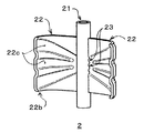
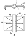
より具体的には、ガイド部材22は板状に形成された部材であり、ガイド部材22を波板状に形成することにより、溝22cが形成されている。溝22cは、ガイド部材22がコイルに向かう方向に湾曲もしくは屈曲する周方向端部(冷却液供給管21とは反対側の部分)22bに形成されていることが好ましい。
11 冷却液供給管
12 ガイド部材
13 第1吐出孔
14 第2吐出孔
91 ロータ
94 ステータ
92 ステータコア
93 ステータコイル
Claims (6)
- 軸周りに回転可能なロータと、前記ロータを取り囲むように前記ロータの外周部に設けられたステータコアおよび前記ステータコアに捲回されるステータコイルを有するステータと、を備える回転電機の冷却構造であって、
前記ロータの軸方向に延在するように設けられ、冷却液が流通する管路と、前記ステータコイルに対し冷却液を吐出する少なくとも1つ以上の吐出孔とを有する冷却液供給管を備え、
前記冷却液供給管に一体化されたガイド部材を備え、
前記ガイド部材は、冷却液供給管との接続部付近では、回転電機の周方向に沿って延在すると共に、周方向の端部にかけて前記ステータコイルに向かう方向に屈曲もしくは湾曲しており、
前記吐出孔の少なくとも一部は、軸方向に沿って見て回転電機の周方向に沿う方向に冷却液が吐出されるよう設けられ、当該吐出孔から吐出された冷却液がガイド部材の表面に沿って流れて前記ステータコイルに導かれる、
回転電機の冷却構造。 - 前記ガイド部材には溝が形成されていて、吐出孔から吐出された冷却液が前記溝に沿って流れて、ステータコイルに導かれる、
請求項1に記載の回転電機の冷却構造。 - 前記ガイド部材の周方向端部における前記溝の軸方向位置と、当該溝に冷却液を吐出する吐出孔の軸方向位置とが、異なる位置とされた、
請求項2に記載の回転電機の冷却構造。 - 少なくとも前記ガイド部材の周方向端部が波板状に形成されている、
請求項2に記載の回転電機の冷却構造。 - 前記ガイド部材には複数のリブが立設されていて、リブとリブの間が前記溝となる、
請求項2に記載の回転電機の冷却構造。 - 回転電機の径方向に沿って見て、周方向に対し傾斜した方向に、吐出孔から冷却液が吐出されて、当該冷却液がガイド部材により導かれる、
請求項1に記載の回転電機の冷却構造。
Priority Applications (1)
| Application Number | Priority Date | Filing Date | Title |
|---|---|---|---|
| JP2017212889A JP6877314B2 (ja) | 2017-11-02 | 2017-11-02 | 回転電機の冷却構造 |
Applications Claiming Priority (1)
| Application Number | Priority Date | Filing Date | Title |
|---|---|---|---|
| JP2017212889A JP6877314B2 (ja) | 2017-11-02 | 2017-11-02 | 回転電機の冷却構造 |
Publications (2)
| Publication Number | Publication Date |
|---|---|
| JP2019088057A JP2019088057A (ja) | 2019-06-06 |
| JP6877314B2 true JP6877314B2 (ja) | 2021-05-26 |
Family
ID=66763514
Family Applications (1)
| Application Number | Title | Priority Date | Filing Date |
|---|---|---|---|
| JP2017212889A Active JP6877314B2 (ja) | 2017-11-02 | 2017-11-02 | 回転電機の冷却構造 |
Country Status (1)
| Country | Link |
|---|---|
| JP (1) | JP6877314B2 (ja) |
Families Citing this family (1)
| Publication number | Priority date | Publication date | Assignee | Title |
|---|---|---|---|---|
| EP4145676A4 (en) * | 2020-04-26 | 2024-01-10 | SAIC MOTOR Corporation Limited | COOLING SYSTEM FOR NEW ENERGY AUTOMOTIVE DRIVE MOTOR |
Family Cites Families (8)
| Publication number | Priority date | Publication date | Assignee | Title |
|---|---|---|---|---|
| JPS52123610U (ja) * | 1976-03-18 | 1977-09-20 | ||
| JP5207083B2 (ja) * | 2010-01-28 | 2013-06-12 | アイシン・エィ・ダブリュ株式会社 | ステータの冷却構造 |
| JP5349376B2 (ja) * | 2010-03-15 | 2013-11-20 | トヨタ自動車株式会社 | 回転電機の冷却構造 |
| KR101238209B1 (ko) * | 2010-11-29 | 2013-03-04 | 엘지전자 주식회사 | 전동기 |
| JP2012130119A (ja) * | 2010-12-14 | 2012-07-05 | Toyota Motor Corp | 回転電機 |
| JP2013126311A (ja) * | 2011-12-15 | 2013-06-24 | Toyota Motor Corp | 回転電機 |
| JP6102203B2 (ja) * | 2012-11-16 | 2017-03-29 | アイシン精機株式会社 | 回転電機 |
| JP2015006036A (ja) * | 2013-06-19 | 2015-01-08 | アイシン・エィ・ダブリュ株式会社 | モータ冷却構造 |
-
2017
- 2017-11-02 JP JP2017212889A patent/JP6877314B2/ja active Active
Also Published As
| Publication number | Publication date |
|---|---|
| JP2019088057A (ja) | 2019-06-06 |
Similar Documents
| Publication | Publication Date | Title |
|---|---|---|
| JP5261052B2 (ja) | 回転電機及び回転電機冷却システム | |
| US9729027B2 (en) | Cooling structure of rotary electric machine | |
| US7800259B2 (en) | Stator assembly for use in a fluid-cooled motor and method of making the same | |
| EP3116107B1 (en) | Electric motor | |
| US20100085706A1 (en) | Helical conduit enabled for casting inside a housing | |
| US20160141921A1 (en) | Helical heat exchanger for electric motors | |
| JP5751065B2 (ja) | ロータのエンドプレート、および回転電機 | |
| JP2011101584A (ja) | 電気機械装置用の冷却装置、電気機械装置、及び自動車 | |
| JP6658627B2 (ja) | 回転電機 | |
| CN104953767A (zh) | 具有转子冷却组件的电机 | |
| US20130076171A1 (en) | Electric machine module cooling system and method | |
| JP2019161798A (ja) | 回転電機の冷却構造体 | |
| JP2016144270A (ja) | 回転電機の冷却構造 | |
| JP2009195082A (ja) | ステータの冷却構造 | |
| JP5979077B2 (ja) | 回転電機 | |
| JP6452164B2 (ja) | 回転電機のステータ | |
| CN103475117A (zh) | 电机模块冷却系统和方法 | |
| JP6877315B2 (ja) | 回転電機の冷却構造 | |
| JP6877314B2 (ja) | 回転電機の冷却構造 | |
| KR102490601B1 (ko) | 냉각구조 일체형 구동모터 | |
| KR20130123317A (ko) | 전기 기계 모듈 냉각 시스템 및 방법 | |
| JP5652305B2 (ja) | 回転電機用ステータ | |
| JP2010206928A (ja) | リニアモータ、リニアモータの電機子、リニアモータの電機子の製造方法 | |
| JP6130940B1 (ja) | モータ | |
| KR101477475B1 (ko) | 미로형 냉각 구조를 구비한 전기기기 |
Legal Events
| Date | Code | Title | Description |
|---|---|---|---|
| A621 | Written request for application examination |
Free format text: JAPANESE INTERMEDIATE CODE: A621 Effective date: 20200825 |
|
| A977 | Report on retrieval |
Free format text: JAPANESE INTERMEDIATE CODE: A971007 Effective date: 20210414 |
|
| TRDD | Decision of grant or rejection written | ||
| A01 | Written decision to grant a patent or to grant a registration (utility model) |
Free format text: JAPANESE INTERMEDIATE CODE: A01 Effective date: 20210420 |
|
| A61 | First payment of annual fees (during grant procedure) |
Free format text: JAPANESE INTERMEDIATE CODE: A61 Effective date: 20210427 |
|
| R150 | Certificate of patent or registration of utility model |
Ref document number: 6877314 Country of ref document: JP Free format text: JAPANESE INTERMEDIATE CODE: R150 |