JP6957841B2 - Manufacturing method of synthetic resin container - Google Patents
Manufacturing method of synthetic resin container Download PDFInfo
- Publication number
- JP6957841B2 JP6957841B2 JP2016147016A JP2016147016A JP6957841B2 JP 6957841 B2 JP6957841 B2 JP 6957841B2 JP 2016147016 A JP2016147016 A JP 2016147016A JP 2016147016 A JP2016147016 A JP 2016147016A JP 6957841 B2 JP6957841 B2 JP 6957841B2
- Authority
- JP
- Japan
- Prior art keywords
- molding
- bottom mold
- mold
- base
- container
- Prior art date
- Legal status (The legal status is an assumption and is not a legal conclusion. Google has not performed a legal analysis and makes no representation as to the accuracy of the status listed.)
- Active
Links
- 238000004519 manufacturing process Methods 0.000 title claims description 19
- 229920003002 synthetic resin Polymers 0.000 title claims description 19
- 239000000057 synthetic resin Substances 0.000 title claims description 19
- 238000000465 moulding Methods 0.000 claims description 50
- 238000000071 blow moulding Methods 0.000 claims description 27
- 230000002093 peripheral effect Effects 0.000 claims description 19
- 238000003780 insertion Methods 0.000 claims description 13
- 230000037431 insertion Effects 0.000 claims description 13
- 238000000034 method Methods 0.000 claims description 9
- 229920005989 resin Polymers 0.000 claims description 6
- 239000011347 resin Substances 0.000 claims description 6
- 230000015572 biosynthetic process Effects 0.000 claims description 2
- 239000000543 intermediate Substances 0.000 claims 3
- 238000003786 synthesis reaction Methods 0.000 claims 1
- -1 polyethylene terephthalate Polymers 0.000 description 7
- 230000037303 wrinkles Effects 0.000 description 6
- 101150061927 BMP2 gene Proteins 0.000 description 3
- 230000007812 deficiency Effects 0.000 description 3
- 229920000139 polyethylene terephthalate Polymers 0.000 description 3
- 239000005020 polyethylene terephthalate Substances 0.000 description 3
- 229920005992 thermoplastic resin Polymers 0.000 description 3
- 238000012986 modification Methods 0.000 description 2
- 230000004048 modification Effects 0.000 description 2
- 239000004033 plastic Substances 0.000 description 2
- 229920003023 plastic Polymers 0.000 description 2
- 229920000728 polyester Polymers 0.000 description 2
- 230000001105 regulatory effect Effects 0.000 description 2
- 230000000630 rising effect Effects 0.000 description 2
- 238000007789 sealing Methods 0.000 description 2
- 238000007493 shaping process Methods 0.000 description 2
- 229920001169 thermoplastic Polymers 0.000 description 2
- 239000004416 thermosoftening plastic Substances 0.000 description 2
- LLLVZDVNHNWSDS-UHFFFAOYSA-N 4-methylidene-3,5-dioxabicyclo[5.2.2]undeca-1(9),7,10-triene-2,6-dione Chemical compound C1(C2=CC=C(C(=O)OC(=C)O1)C=C2)=O LLLVZDVNHNWSDS-UHFFFAOYSA-N 0.000 description 1
- NIXOWILDQLNWCW-UHFFFAOYSA-M Acrylate Chemical compound [O-]C(=O)C=C NIXOWILDQLNWCW-UHFFFAOYSA-M 0.000 description 1
- NLHHRLWOUZZQLW-UHFFFAOYSA-N Acrylonitrile Chemical compound C=CC#N NLHHRLWOUZZQLW-UHFFFAOYSA-N 0.000 description 1
- 102100024506 Bone morphogenetic protein 2 Human genes 0.000 description 1
- 239000004278 EU approved seasoning Substances 0.000 description 1
- 101000762366 Homo sapiens Bone morphogenetic protein 2 Proteins 0.000 description 1
- 239000004698 Polyethylene Substances 0.000 description 1
- 101100218949 Rattus norvegicus Bmp3 gene Proteins 0.000 description 1
- 238000010521 absorption reaction Methods 0.000 description 1
- 235000013361 beverage Nutrition 0.000 description 1
- 238000000748 compression moulding Methods 0.000 description 1
- 229920001577 copolymer Polymers 0.000 description 1
- 230000006837 decompression Effects 0.000 description 1
- 235000011194 food seasoning agent Nutrition 0.000 description 1
- 238000001746 injection moulding Methods 0.000 description 1
- 235000013372 meat Nutrition 0.000 description 1
- 229920003207 poly(ethylene-2,6-naphthalate) Polymers 0.000 description 1
- 229920000747 poly(lactic acid) Polymers 0.000 description 1
- 229920001230 polyarylate Polymers 0.000 description 1
- 229920001707 polybutylene terephthalate Polymers 0.000 description 1
- 229920000515 polycarbonate Polymers 0.000 description 1
- 239000004417 polycarbonate Substances 0.000 description 1
- 229920000573 polyethylene Polymers 0.000 description 1
- 239000011112 polyethylene naphthalate Substances 0.000 description 1
- 239000004626 polylactic acid Substances 0.000 description 1
Images


Landscapes
- Moulds For Moulding Plastics Or The Like (AREA)
- Blow-Moulding Or Thermoforming Of Plastics Or The Like (AREA)
- Stackable Containers (AREA)
- Containers Having Bodies Formed In One Piece (AREA)
Description
本発明は、スタッキング可能な合成樹脂製容器の製造方法に関する。 The present invention relates to a method of manufacturing a container made of stackable plastic.
従来、ポリエチレンテレフタレートなどの熱可塑性樹脂を用いて有底筒状のプリフォームを形成し、次いで、このプリフォームを二軸延伸ブロー成形などによってボトル状に成形してなる合成樹脂製の容器が、各種飲料品、各種調味料等を内容物とする容器として広い分野で一般的に利用されている。 Conventionally, a container made of synthetic resin, which is formed by forming a bottomed tubular preform using a thermoplastic resin such as polyethylene terephthalate and then molding this preform into a bottle shape by biaxial stretching blow molding or the like. It is generally used in a wide range of fields as a container containing various beverages and various seasonings.
そして、この種の合成樹脂製容器に関し、他の容器の口部側が挿入可能とされた陥没凹部を容器底部に設けて、二以上の容器を上下に積み重ねられるようにした、スタッキング可能(stackable)な容器が知られている(特許文献1参照)。 Then, with respect to this type of synthetic resin container, a recessed recess in which the mouth side of another container can be inserted is provided at the bottom of the container so that two or more containers can be stacked up and down, which is stackable. Containers are known (see Patent Document 1).
しかしながら、このようなスタッキング可能な容器において、その容器底部に設けられた陥没凹部は、挿入された容器の口部側を覆い隠すことができる程度に、容器内方に大きく陥没した形状になっている。このため、ブロー成形に際しては、例えば、図10に示すように、かかる陥没凹部を成形する底型BMp1にプリフォームPFの延伸が妨げられてしまい、型内の容器底部の接地部を成形する部位CGまでプリフォームPFが延伸されずに、接地部が成形できなくなってしまうという問題がある。このような問題は、底部全体の面積に対して、陥没凹部の占める割合が大きく、接地部の面積が小さい容器で特に顕著である。 However, in such a stackable container, the recessed recess provided at the bottom of the container has a shape that is largely recessed inward to the extent that the mouth side of the inserted container can be covered. There is. Therefore, at the time of blow molding, for example, as shown in FIG. 10, the bottom mold BMp1 for molding the recessed recess is hindered from stretching the preform PF, and a portion for molding the ground contact portion at the bottom of the container in the mold. There is a problem that the preform PF is not stretched to CG and the ground contact portion cannot be formed. Such a problem is particularly remarkable in a container in which the recessed recess occupies a large proportion of the total area of the bottom and the area of the ground contact portion is small.
また、このような問題を解決するには、例えば、図11に示すように、陥没凹部を成形する底型BMp2を可動式にすることが考えられる。すなわち、型内の底部の接地部を成形する部位CGを越えて、下死点に位置する底型BMp2に到達するまでプリフォームPFを延伸させてから、底型BMp2を上死点まで上昇させて、当該部位CGを越えて延伸された部分を押し戻しながら反転させることによって、陥没凹部が設けられた底部形状を賦形することが考えられる。 Further, in order to solve such a problem, for example, as shown in FIG. 11, it is conceivable to make the bottom mold BMp2 for forming the recessed recess movable. That is, the preform PF is extended until it reaches the bottom BMp2 located at the bottom dead center beyond the portion CG that forms the ground contact portion at the bottom of the mold, and then the bottom BMp2 is raised to the top dead center. Therefore, it is conceivable to shape the bottom shape provided with the recessed recess by inversion while pushing back the portion extended beyond the portion CG.
しかしながら、この場合には、型内の底部の接地部を成形する部位CGを越えて延伸された部分が、これを反転させて陥没凹部を成形するための反転代として十分な長さとなるように、陥没凹部の深さに応じて、底型BMp2のストロークS0を長くしなければならないが、そのためには、装置の大型化を招き、その形成は容易にできるものではない。 However, in this case, the portion extended beyond the portion CG for forming the ground contact portion at the bottom of the mold is set to have a sufficient length as an inversion allowance for inverting this and forming the recessed recess. , depending on the depth of the depression recess, it is necessary to increase the stroke S 0 of the bottom type BMP2, for that purpose, leads to enlargement of the apparatus, its formation is not capable of easily.
そこで、本発明者らは、図12に示すように、底型挿通部の径を拡げて、その内周面と底型MBp3との間に、延伸されたプリフォームが入り込める空間を形成することで、底型BMp3のストロークS1を長くせずとも、延伸されたプリフォームに十分な長さの反転代を確保できると考えて検討を試みた。
しかしながら、この場合には、延伸されたプリフォームの先端側はフリーな状態にあるため、プリフォームに僅かにでも偏肉があると、その影響で延伸に過不足が生じてしまう虞がある。そして、延伸が不足すると反転代が確保できずに賦形不良となり、延伸が過剰であると反転したときの肉余りによってバリが発生してしまうという問題がある。
Therefore, as shown in FIG. 12, the present inventors increase the diameter of the bottom mold insertion portion to form a space in which the stretched preform can enter between the inner peripheral surface thereof and the bottom mold MBp3. Therefore, it was considered that a sufficient length of inversion allowance could be secured for the stretched preform without lengthening the stroke S1 of the bottom type BMp3, and an attempt was made.
However, in this case, since the tip end side of the stretched preform is in a free state, if the preform has even a slight uneven thickness, there is a possibility that excess or deficiency may occur due to the influence. Then, if the stretching is insufficient, the inversion allowance cannot be secured and the shaping becomes poor, and if the stretching is excessive, there is a problem that burrs are generated due to the excess meat when the inversion occurs.
本発明は、上記したような事情に鑑みてなされたものであり、他の容器の口部側が挿入可能とされた陥没凹部を容器底部に設けて、二以上の容器を上下に積み重ねられるようにした合成樹脂製容器において、陥没凹部が設けられた底部形状が賦形性良く良好に成形されたスタッキング可能な合成樹脂製容器の製造方法の提供を目的とする。 The present invention has been made in view of the above circumstances, and a recessed recess into which the mouth side of another container can be inserted is provided at the bottom of the container so that two or more containers can be stacked one above the other. in the synthetic resin container, and an object thereof is to provide a method for manufacturing a bottom shaped recessed recess is provided shaping property may well shaped stackable plastic containers.
本発明に係る合成樹脂製容器の製造方法は、以下の方法としてある。 The method for manufacturing a synthetic resin container according to the present invention is as follows.
すなわち、口部、肩部、胴部、及び底部を備え、前記底部に、他の容器の口部側が挿入可能とされた陥没凹部が設けられて、二以上の容器を上下に積み重ねられるようにした合成樹脂製容器の製造方法であって、前記底部の接地部の内周縁に沿って立ち上る基部と、前記基部に対して同心状に縮径して、前記他の容器の口部に装着された蓋体が遊嵌状に嵌入する蓋体嵌入部とを有し、前記基部と前記蓋体嵌入部とが段部を介して連接されている前記陥没凹部に対応する形状の底型が、型内の前記接地部を成形する部位の内周縁に沿って穿設された底型挿通部に昇降可能に挿通されるとともに、前記底型が、下死点に位置したときに、前記底型の軸心を含む鉛直面において、前記底型挿通部の内周面と、前記段部を成形する段部成形部のエッジ部を含む水平面と、前記蓋体嵌入部を成形する蓋体嵌入部成形部の側面とに接する三点内接円の曲率半径Rが、5mm以上となるように形成されたブロー成形型を用い、加熱、軟化させてブロー成形が可能な状態とされたプリフォームを前記ブロー成形型にセットして、前記底型を下死点に待機させた状態でブロー成形を開始し、前記接地部を成形する前記部位を越えて、下死点に位置する前記底型に到達するまで前記プリフォームを延伸させて、前記底型挿通部の内周面と、前記蓋体嵌入部成形部と、前記段部成形部とで囲まれる空間内に、延伸された前記プリフォームの先端側を入り込ませた成形中間体とし、次いで、前記底型を上昇させて、前記成形中間体のうち、前記接地部を成形する前記部位を越えて延伸された部分を押し戻しながら反転させつつ、ブロー成形を完了することを特徴とする。 That is, it is provided with a mouth, a shoulder, a body, and a bottom, and a recessed recess into which the mouth side of another container can be inserted is provided in the bottom so that two or more containers can be stacked one above the other. This is a method for manufacturing a synthetic resin container, which is attached to the mouth of the other container by reducing the diameter concentrically with respect to the base portion rising along the inner peripheral edge of the ground contact portion at the bottom. A bottom mold having a lid fitting portion into which the lid is loosely fitted and having a shape corresponding to the recessed recess in which the base portion and the lid fitting portion are connected via a step portion is provided. wherein the vertically movable through the bottom mold insertion portion drilled along the inner periphery of a portion forming the ground part Rutotomoni in the mold, when the bottom mold is positioned at the bottom dead center, the bottom mold On the vertical surface including the axis of the bottom mold, the inner peripheral surface of the bottom mold insertion portion, the horizontal plane including the edge portion of the step portion molding portion for molding the step portion, and the lid fitting portion for molding the lid fitting portion. Using a blow molding mold formed so that the radius of curvature R of the three-point inscribed circle in contact with the side surface of the molded portion is 5 mm or more, the preform is heated and softened so that blow molding is possible. Blow molding is started in a state where the bottom mold is set in the blow molding mold and the bottom mold is kept waiting at the bottom dead point, and the bottom mold located at the bottom dead point is reached beyond the portion where the ground contact portion is molded. by stretching the preform to reach the inner peripheral surface of the bottom mold insertion portion, and the lid fitting portion forming section, surrounded by the space between the stepped portion forming part, stretched the preform The tip side of the molding intermediate is formed, and then the bottom mold is raised to invert the molded intermediate while pushing back the portion of the molding intermediate that is extended beyond the portion where the ground contact portion is molded. , It is characterized by completing blow molding.
本発明に係る合成樹脂製容器の製造方法によれば、底型のストロークを長くせずとも、十分な長さの反転代を確保することが可能となり、さらに、延伸されたプリフォームの先端側が、底型の段部成形部によって規制されるため、反転代となる部分の延伸に過不足が生じないようにすることが可能である。 According to the method for manufacturing a synthetic resin container according to the present invention, it is possible to secure a sufficient length of inversion allowance without lengthening the stroke of the bottom mold, and further, the tip side of the stretched preform is because it is regulated by the stepped portion forming part of the bottom mold, Ru can der to ensure that excess or deficiency in the stretching of the portion to be a reversal allowance does not occur.
その結果、合成樹脂製容器の陥没凹部が設けられた底部の形状を賦形性よく良好に成形することができる。 As a result , the shape of the bottom portion of the synthetic resin container provided with the recessed recesses can be well formed with good shapeability.
以下、本発明の好ましい実施形態について、図面を参照しつつ説明する。 Hereinafter, preferred embodiments of the present invention will be described with reference to the drawings.
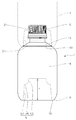
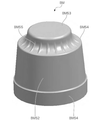
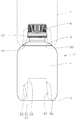
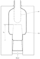
本発明に係る容器1は、口部2、肩部3、胴部4、及び底部5を備えており、本発明の一実施形態として図示する容器1は、胴部4が円筒状に形成された、一般に、丸形ボトルと称される容器形状を有している。
The
このような容器1は、熱可塑性樹脂を使用して射出成形や圧縮成形などにより有底筒状のプリフォームを成形し、このプリフォームを二軸延伸ブロー成形などにより所定の容器形状に成形することによって製造される。
In such a
容器1を製造するにあたり、使用する熱可塑性樹脂としては、ブロー成形が可能な任意の樹脂を使用することができる。具体的には、ポリエチレンテレフタレート,ポリブチレンテレフタレート,ポリエチレンナフタレート,非晶ポリアリレート,ポリ乳酸又はこれらの共重合体などの熱可塑性ポリエステル,これらの樹脂あるいは他の樹脂とブレンドされたものなどが好適である。特に、ポリエチレンテレフタレートなどのエチレンテレフタレート系熱可塑性ポリエステルが、好適に使用される。また、ポリカーボネート,アクリロニトリル樹脂,ポリプロピレン,プロピレン−エチレン共重合体,ポリエチレンなども使用することができる。
As the thermoplastic resin used in manufacturing the
口部2は、内容物の取り出し口となる円筒状の部位であり、かかる口部2には、容器内を密封する蓋体6が取り付けられる。
なお、図1では、蓋体6の一部を切り欠いて示している。
The
In addition, in FIG. 1, a part of the lid body 6 is cut out and shown.
また、口部2の下端は、胴部4に向かって拡径して口部2と胴部4との間をつなぐ肩部3に連接しており、図示する例において、肩部3は円錐台状に形成されている。
Further, the lower end of the
胴部4は、容器1の高さ方向の大半を占める部位であり、上端が肩部3に連接し、下端が底部5に連接している。特に図示しないが、胴部4には、いわゆるホットパックにより内容物を充填、密封した後に、常温に冷却された容器内の圧力減少分を吸収する減圧吸収パネルや、横方向の耐荷重強度を高めるための環状の横溝などを、必要に応じて設けることができる。
The
ここで、高さ方向とは、口部2を上にして容器1を水平面に正立させたときに、水平面に直交する方向をいうものとし、この状態で容器1の上下左右及び縦横の方向を規定するものとする。また、容器1を成形するブロー成形型100についても同様とし、成形される容器1に対応させて、その方向を規定するものとする。
Here, the height direction means a direction orthogonal to the horizontal plane when the
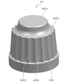
また、底部5は、容器1を水平面に正立させたときに、当該水平面に接触して、容器1を自立可能とするための接地部50を有しており、底部5の側面は、接地部50の外周縁に沿って斜め上方に湾曲しながら胴部4の下端に連接している。図示する例において、接地部50は、周方向に沿って環状に延在するように形成されているが、容器1が自立可能であれば、その具体的な形状は限定されない。
Further, the
また、底部5には、その中央部を容器内方に陥没させて、他の容器1の口部2側が挿入可能とされた陥没凹部51が設けられている。このような陥没凹部51を設けることで、容器1は、図1に示すように、二以上の容器1を上下に積み重ねられるようになっている。
Further, the
陥没凹部51は、接地部50の内周縁に沿って立ち上る基部52と、かかる基部52に対して同心状に縮径して、他の容器1の口部2に装着された蓋体6が遊嵌状に嵌入する蓋体嵌入部53とを有し、基部52と蓋体嵌入部53とが段部54を介して連接されている。
The recessed
本実施形態において、蓋体嵌入部53は、容器1の軸心と同軸に形成され、二以上の容器1を同軸上に積み重ねられるようにしてあり、肩部3には、上方に積み重ねられた容器1の陥没凹部51の開口部周縁に係合する環状係合部30を設けておくのが好ましい。このようにすることで、容器1をより安定した状態で積み重ねることができる。
In the present embodiment, the
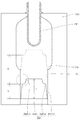
このような容器1は、容器内方に大きく陥没する陥没凹部51が設けられた底部5の形状が賦形性よく成形されるように、陥没凹部51を成形する底型BMを可動式としたブロー成形型100を用いて製造することができる(図2参照)。
In such a
ブロー成形型100は、その型内の底部5の接地部50を成形する部位CGの内周縁に沿って鉛直方向に穿設された底型挿通部に、底型BMが挿通された構成とされている。そして、底型BMは、かかる底型挿通部の内周面101を摺動する摺動部BM0を有しており、図示しない駆動装置によって底型挿通部内を鉛直方向に昇降可能とされている。
また、底型BMは、陥没凹部51に対応する形状とされ、上記摺動部BM0とともに、蓋体嵌入部53を成形する蓋体嵌入部成形部BM53と、段部54を成形する段部成形部BM54と、基部52を成形する基部成形部BM52とを有している。
The blow molding die 100 has a configuration in which the bottom die BM is inserted into a bottom die insertion portion formed in the vertical direction along the inner peripheral edge of the portion CG for forming the
Further, the bottom mold BM has a shape corresponding to the recessed
容器1を製造するには、まず、図2に示すように、加熱、軟化させてブロー成形が可能な状態とされたプリフォームPFをセットするとともに、底型BMを下死点で待機させた状態で、ブロー成形型100を型閉じする。そして、図示しない延伸ロッドを下動させつつ、プリフォームPFの内部にブローエアーを吹き込んでブロー成形を開始する。
In order to manufacture the
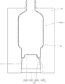
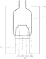
このとき、延伸ロッドの下動速度やブローエアーの圧力などを適宜調整することで、プリフォームPFを均一に延伸することができ、型内の底部5の接地部50を成形する部位CGを越えて、下死点に位置する底型BMに到達するまでプリフォームPFを延伸させて、成形中間体MMとする(図4参照)。次いで、底型BMを上死点まで上昇させて、当該部位CGを越えて延伸された部分を押し戻しながら反転させつつ、ブロー成形を完了させる。これにより、延伸されたプリフォームPFをブロー成形型100の成形面に密着させて、その形状を賦形する(図5参照)。 At this time, the preform PF can be uniformly stretched by appropriately adjusting the downward speed of the stretching rod, the pressure of the blow air, etc. Then, the preform PF is stretched until it reaches the bottom mold BM located at the bottom dead center to obtain a molding intermediate MM (see FIG. 4). Next, the bottom mold BM is raised to the top dead center, and the blow molding is completed while pushing back and reversing the portion stretched beyond the portion CG. As a result, the stretched preform PF is brought into close contact with the molding surface of the blow molding die 100 to shape the shape (see FIG. 5).
このようにして容器1を製造するにあたり、本実施形態にあっては、ブロー成形により延伸されたプリフォームPFの先端側が、底型挿通部の内周面101と、底型BMの蓋体嵌入部成形部BM53と、底型BMの段部成形部BM54とで囲まれる空間内に入り込み(図4参照)、型内の底部5の接地部50を成形する部位CGを越えて延伸された部分が、これを反転させて陥没凹部51を成形するための反転代として十分な長さとなるようにすることができる。このため、底型BMのストロークSを長くせずとも、十分な長さの反転代を確保することが可能となる。さらに、本実施形態によれば、延伸されたプリフォームの先端側は、底型BMの段部成形部BM54によって規制されるため、反転代となる部分の延伸に過不足が生じないようにすることも可能であり、陥没凹部51が設けられた底部5の形状を賦形性よく良好に成形することができる。
In manufacturing the
また、陥没凹部51が設けられた底部5の形状を、賦形性よくより良好に成形できるようにするには、段部形成部BM54は、底型BMが下死点に位置したときに、型内の底部5の接地部50を成形する部位CGから段部形成部BM54までの高さ方向に沿った距離が、基部成形部BM52の高さHと同等となる位置にあるのが好ましい。つまり、底型BMのストロークSは、基部成形部BM52の高さHの2倍であることが好ましい。さらに、基部成形部BM52の下端部から蓋体嵌入部成形部BM53の上端部までの高さhは、20mm以上であるのが好ましい。
なお、蓋体嵌入部成形部BM53の側面と、基部成形部BM52の側面は、抜き勾配を考慮してテーパー面とするのが好ましい。また、段部成形部BM54の蓋体嵌入部成形部BM53側には、賦形性を考慮してRを付けるのが好ましい。
Further, in order to enable the shape of the
The side surface of the lid fitting portion molded portion BM53 and the side surface of the base molded portion BM52 are preferably tapered surfaces in consideration of the draft. Further, it is preferable to add R to the lid fitting portion molding portion BM53 side of the step portion molding portion BM54 in consideration of shapeability.
また、蓋体嵌入部成形部BM53は、底型BMの軸心を含む鉛直面において、底型挿通部の内周面101と、底型BMの段部成形部BM54のエッジ部を含む水平面と、底型BMの蓋体嵌入部成形部BM53の側面とに接する三点内接円iCの曲率半径が、5mm以上となるように形成するのが好ましい(図3参照)。
なお、図3は、図2中一点鎖線で囲む部分を拡大して示す要部拡大図である。
Further, the lid fitting portion molded portion BM53 has a horizontal surface including an inner
Note that FIG. 3 is an enlarged view of a main part in FIG. 2 in which the portion surrounded by the alternate long and short dash line is enlarged.
このようにすることで、段部成形部BM54に到達した延伸されたプリフォームPFの先端形状が、周方向に沿って不揃いとなるのを抑制することができる。これにより、成形中間体MMの再現性の高い安定した成形が可能となり、ブロー成形における賦形性を向上させることができる。 By doing so, it is possible to prevent the tip shape of the stretched preform PF that has reached the step forming portion BM54 from becoming uneven along the circumferential direction. As a result, stable molding with high reproducibility of the molding intermediate MM becomes possible, and the shapeability in blow molding can be improved.
その結果、ブロー成形を経て最終的に製造された容器1は、その軸心を含む鉛直面において、接地部50の内周縁を通る鉛直線と、段部54のエッジ部を含む水平面と、蓋体嵌入部53の側面とに接する三点内接円の曲率半径が、5mm以上となるように形成され、底部5の形状が賦形性よく良好に成形されたものとなる。
As a result, the
また、底型BMを上昇させて、型内の底部の接地部50を成形する部位CGを越えて延伸された部分を押し戻しながら反転させる際に、当該部分は容器内方に巻き込まれながら底型BMに賦形されて陥没凹部51に成形される。このため、周方向に沿った長さ(周長)が一致せず、反転前と反転後の周長差に起因して、成形された陥没凹部51に皺が発生してしまうことがある。
Further, when the bottom mold BM is raised and the portion stretched beyond the portion CG for forming the
底型BMには、このような周長差を吸収して皺の発生を抑制し、又は皺が発生しても目立たなくようにするための凹凸形状を設けておくのが好ましい。
例えば、図6に示すように、蓋体嵌入部成形部BM53の側面と段部成形部BM54とに跨る複数の凸条BM55を周方向に沿って形成することによって、当該凹凸形状を設けるようにしてもよい。このような凹凸形状を設けた底型BMを用いて成形された容器1は、陥没凹部51に、蓋体嵌入部53の側面と段部54とに跨る複数の凹溝が周方向に沿って形成され、顕著な皺の発生が抑制されたものとなる。
It is preferable that the bottom type BM is provided with an uneven shape for absorbing such a difference in circumference to suppress the occurrence of wrinkles or to make the wrinkles inconspicuous even if they occur.
For example, as shown in FIG. 6, a plurality of convex ridges BM55 straddling the side surface of the lid fitting portion molding portion BM53 and the step portion molding portion BM54 are formed along the circumferential direction to provide the uneven shape. You may. In the
また、底型BMに設ける凹凸形状は、図7に示すように、基部成形部BM52の側面に複数の凹溝BM56を周方向に沿って形成することによって設けるようにしてもよい。このような凹凸形状を設けた底型BMを用いて成形された容器1は、陥没凹部51の基部52の側面に複数の凸条が周方向に沿って形成され、顕著な皺の発生が抑制されたものとなる。
Further, as shown in FIG. 7, the uneven shape provided on the bottom mold BM may be provided by forming a plurality of concave grooves BM56 on the side surface of the base forming portion BM52 along the circumferential direction. In the
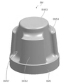
また、図8に示すように、基部成形部BM52を部分的に切り欠いて凹凸形状を設けることによっても顕著な皺の発生を抑制できるが、この場合には、基部成形部BM52を部分的に切り欠いた部位BM57に、蓋体嵌入部成形部BM53の側面と面一となる面があらわれるようにするのが好ましい。このようにすることで、成形された容器1の陥没凹部51には、蓋体嵌入部53と面一に延在するリブ部57が形成される(図9参照)。これにより、陥没凹部51に挿入された他の容器1の口部側がリブ部57によりサポートされ、容器1をより安定した状態で積み重ねることができる。このような態様とする場合、リブ部57は、周方向に沿って等間隔に三つ以上形成するのが好ましい。
Further, as shown in FIG. 8, the occurrence of remarkable wrinkles can be suppressed by partially cutting out the base molding portion BM52 to provide an uneven shape. In this case, the base molding portion BM52 is partially cut out. It is preferable that the notched portion BM57 has a surface that is flush with the side surface of the lid fitting portion molded portion BM53. By doing so, a
以上、本発明について、好ましい実施形態を示して説明したが、本発明は、前述した実施形態にのみ限定されるものではなく、本発明の範囲で種々の変更実施が可能であることはいうまでもない。 Although the present invention has been described above with reference to preferred embodiments, it goes without saying that the present invention is not limited to the above-described embodiments, and various modifications can be made within the scope of the present invention. Nor.
例えば、前述した実施形態では、丸形ボトルと称される容器形状を有する容器1を図示して説明しているが、図示する例は、本発明の一実施形態を示しているに過ぎず、本発明が適用される容器形状は、図示するものには限定されない。本発明は、二以上の容器1を上下に積み重ねられるようにするために、底部5に設けた陥没凹部51の形状に技術的な特徴があり、それ以外の部位の具体的な形状については、必要に応じて適宜変更することができる。
For example, in the above-described embodiment, the
すなわち、本発明は、底部5に設けられた陥没凹部51が、底部5の接地部50の内周縁に沿って立ち上る基部52と、基部52に対して同心状に縮径して、他の容器1の口部2に装着された蓋体6が遊嵌状に嵌入する蓋体嵌入部53とを有し、基部52と蓋体嵌入部53とが段部54を介して連接されていれば、これ以外の細部の構成は、前述した実施形態に限定されることなく適宜変更することができる。また、前述した実施形態で説明した細部の構成を適宜取捨選択して組み合わせることもできる。
That is, in the present invention, the recessed
本発明は、スタッキング可能な合成樹脂製容器として広く利用することができる。 The present invention can be widely used as a stackable synthetic resin container.
1 容器
2 口部
3 肩部
4 胴部
5 底部
50 接地部
51 陥没凹部
52 基部
53 蓋体嵌入部
54 段部
100 ブロー成形型
101 底型挿通部の内周面
BM 底型
BM0 摺動部
BM52 基部成形部
BM53 蓋体嵌入部成形部
BM54 段部成形部
1
Claims (5)
前記底部の接地部の内周縁に沿って立ち上る基部と、前記基部に対して同心状に縮径して、前記他の容器の口部に装着された蓋体が遊嵌状に嵌入する蓋体嵌入部とを有し、前記基部と前記蓋体嵌入部とが段部を介して連接されている前記陥没凹部に対応する形状の底型が、型内の前記接地部を成形する部位の内周縁に沿って穿設された底型挿通部に昇降可能に挿通されるとともに、前記底型が、下死点に位置したときに、前記底型の軸心を含む鉛直面において、前記底型挿通部の内周面と、前記段部を成形する段部成形部のエッジ部を含む水平面と、前記蓋体嵌入部を成形する蓋体嵌入部成形部の側面とに接する三点内接円の曲率半径Rが、5mm以上となるように形成されたブロー成形型を用い、
加熱、軟化させてブロー成形が可能な状態とされたプリフォームを前記ブロー成形型にセットして、前記底型を下死点に待機させた状態でブロー成形を開始し、
前記接地部を成形する前記部位を越えて、下死点に位置する前記底型に到達するまで前記プリフォームを延伸させて、前記底型挿通部の内周面と、前記蓋体嵌入部成形部と、前記段部成形部とで囲まれる空間内に、延伸された前記プリフォームの先端側を入り込ませた成形中間体とし、
次いで、前記底型を上昇させて、前記成形中間体のうち、前記接地部を成形する前記部位を越えて延伸された部分を押し戻しながら反転させつつ、ブロー成形を完了することを特徴とする合成樹脂製容器の製造方法。 Synthetic with a mouth, shoulders, body, and bottom, and a recess in the bottom that allows the mouth side of another container to be inserted so that two or more containers can be stacked one above the other. It is a method of manufacturing a resin container.
A lid that rises along the inner peripheral edge of the ground contact portion of the bottom and a lid that is concentrically reduced in diameter with respect to the base and that is attached to the mouth of the other container in a loose fit. The bottom mold having a fitting portion and having a shape corresponding to the recessed recess in which the base portion and the lid fitting portion are connected via a step portion is inside the portion of the mold for forming the ground contact portion. Rutotomoni is vertically movably inserted into a bottom mold insertion portion drilled along the periphery, the bottom type, when positioned at the bottom dead center, in a vertical plane including the bottom mold of the axis, said bottom mold A three-point inscribed circle in contact with the inner peripheral surface of the insertion portion, the horizontal plane including the edge portion of the step portion molding portion for molding the step portion, and the side surface of the lid fitting portion molding portion for molding the lid fitting portion. Using a blow molding mold formed so that the radius of curvature R of is 5 mm or more,
A preform that has been heated and softened so that it can be blow-molded is set in the blow-molding mold, and blow-molding is started with the bottom mold waiting at the bottom dead center.
Beyond the portion for molding the ground portion, until it reaches the bottom mold located at the bottom dead center by stretching the preform, the inner peripheral surface of the bottom mold insertion portion, the lid fitting portion forming and parts, surrounded by the space between the stepped portion forming portions, and allowed enter the distal end side of the stretched the preform molding intermediates,
Next, the synthesis is characterized in that the blow molding is completed while raising the bottom mold and reversing the molding intermediate while pushing back the portion of the molding intermediate that is stretched beyond the portion for molding the ground contact portion. A method for manufacturing a resin container.
Priority Applications (1)
| Application Number | Priority Date | Filing Date | Title |
|---|---|---|---|
| JP2016147016A JP6957841B2 (en) | 2016-07-27 | 2016-07-27 | Manufacturing method of synthetic resin container |
Applications Claiming Priority (1)
| Application Number | Priority Date | Filing Date | Title |
|---|---|---|---|
| JP2016147016A JP6957841B2 (en) | 2016-07-27 | 2016-07-27 | Manufacturing method of synthetic resin container |
Publications (2)
| Publication Number | Publication Date |
|---|---|
| JP2018016344A JP2018016344A (en) | 2018-02-01 |
| JP6957841B2 true JP6957841B2 (en) | 2021-11-02 |
Family
ID=61075785
Family Applications (1)
| Application Number | Title | Priority Date | Filing Date |
|---|---|---|---|
| JP2016147016A Active JP6957841B2 (en) | 2016-07-27 | 2016-07-27 | Manufacturing method of synthetic resin container |
Country Status (1)
| Country | Link |
|---|---|
| JP (1) | JP6957841B2 (en) |
Families Citing this family (2)
| Publication number | Priority date | Publication date | Assignee | Title |
|---|---|---|---|---|
| JP7151139B2 (en) * | 2018-04-09 | 2022-10-12 | 東洋製罐グループホールディングス株式会社 | Polylactic acid container and manufacturing method thereof |
| US12280531B2 (en) | 2020-01-31 | 2025-04-22 | Nissei Asb Machine Co., Ltd. | Mold, blow molding device, and injection molding device |
Family Cites Families (10)
| Publication number | Priority date | Publication date | Assignee | Title |
|---|---|---|---|---|
| JPH05193635A (en) * | 1992-01-14 | 1993-08-03 | Dainippon Printing Co Ltd | Pressure resistant self-supporting container and manufacturing method thereof |
| JP2000153841A (en) * | 1998-11-20 | 2000-06-06 | System Art:Kk | Drink container |
| JP2008044633A (en) * | 2006-08-11 | 2008-02-28 | Hokkai Can Co Ltd | Plastic bottle |
| JP5140847B2 (en) * | 2007-04-02 | 2013-02-13 | 北海製罐株式会社 | Method for producing synthetic resin bottles |
| US10518933B2 (en) * | 2009-12-04 | 2019-12-31 | Plastipak Packaging, Inc. | Stackable plastic container |
| JP5524688B2 (en) * | 2010-04-13 | 2014-06-18 | 北海製罐株式会社 | Blow molding method for synthetic resin bottles |
| FR2970951B1 (en) * | 2011-01-31 | 2013-03-01 | Mezrag Mohamed Seiffeddine Bou | MODULAR CONTAINER COMPRISING A PLURALITY OF AXIALLY FITTED CONTAINERS, AND PROCESS FOR OBTAINING SUCH CONTAINERS BY BLOWING A PREFORM |
| JP6055675B2 (en) * | 2012-12-27 | 2016-12-27 | 株式会社吉野工業所 | Bottle |
| JP6220538B2 (en) * | 2013-03-29 | 2017-10-25 | 株式会社吉野工業所 | Bottle |
| US9278781B1 (en) * | 2014-07-15 | 2016-03-08 | John F. Boldis | Stackable interlocking vessel |
-
2016
- 2016-07-27 JP JP2016147016A patent/JP6957841B2/en active Active
Also Published As
| Publication number | Publication date |
|---|---|
| JP2018016344A (en) | 2018-02-01 |
Similar Documents
| Publication | Publication Date | Title |
|---|---|---|
| JP6628811B2 (en) | Manufacturing method of preform and container | |
| JP6910735B2 (en) | Manufacturing method of synthetic resin container, preform, and synthetic resin container | |
| JP5980813B2 (en) | Parison and container blow molding method using the same | |
| US10737428B2 (en) | Forming mold and injection mold | |
| CN102762357B (en) | A preform suitable for blow-molding into a final shaped container | |
| US7387825B2 (en) | Preform for small flat container and small flat container | |
| JP2011218722A (en) | Blow-molding method for bottle made of synthetic resin | |
| CN109496194A (en) | Plastic bottle with cross-tensioned band portion | |
| JP2018058590A (en) | Plastic container | |
| JP6957841B2 (en) | Manufacturing method of synthetic resin container | |
| JP4315700B2 (en) | Heat-resistant bottle made of polyethylene terephthalate resin | |
| KR102285874B1 (en) | Method for manufacturing resin container parts, mold unit, and blow molding machine having the same | |
| CN101389537A (en) | Mold base for molds for the manufacture of thermoplastic containers and molding apparatus provided with at least one mold provided with the mold base | |
| JP4700297B2 (en) | Grip bottle | |
| JP2017210266A (en) | Synthetic resin blow molded bottle | |
| JP2707421B2 (en) | Double-layer container made of synthetic resin and method for producing the same | |
| JPS6232826Y2 (en) | ||
| JP6820464B2 (en) | Synthetic resin container | |
| JP6641793B2 (en) | Synthetic resin container | |
| CN103052601A (en) | Method for manufacturing glass bottles | |
| KR101804423B1 (en) | Apparatus for manufacturing of container | |
| JP2025077118A (en) | Synthetic resin container | |
| JP2024018825A (en) | Plastic bottles, blow molding molds, and methods for manufacturing plastic bottles | |
| JP2005169698A (en) | Method for forming projection to molded product by biaxial stretch/blow molding method | |
| US20140231375A1 (en) | Pet container having inward thread finish |
Legal Events
| Date | Code | Title | Description |
|---|---|---|---|
| A621 | Written request for application examination |
Free format text: JAPANESE INTERMEDIATE CODE: A621 Effective date: 20190613 |
|
| A977 | Report on retrieval |
Free format text: JAPANESE INTERMEDIATE CODE: A971007 Effective date: 20200605 |
|
| A131 | Notification of reasons for refusal |
Free format text: JAPANESE INTERMEDIATE CODE: A131 Effective date: 20200908 |
|
| A521 | Written amendment |
Free format text: JAPANESE INTERMEDIATE CODE: A523 Effective date: 20201109 |
|
| A131 | Notification of reasons for refusal |
Free format text: JAPANESE INTERMEDIATE CODE: A131 Effective date: 20210608 |
|
| A521 | Written amendment |
Free format text: JAPANESE INTERMEDIATE CODE: A523 Effective date: 20210805 |
|
| TRDD | Decision of grant or rejection written | ||
| A01 | Written decision to grant a patent or to grant a registration (utility model) |
Free format text: JAPANESE INTERMEDIATE CODE: A01 Effective date: 20210907 |
|
| A61 | First payment of annual fees (during grant procedure) |
Free format text: JAPANESE INTERMEDIATE CODE: A61 Effective date: 20210920 |
|
| R150 | Certificate of patent or registration of utility model |
Ref document number: 6957841 Country of ref document: JP Free format text: JAPANESE INTERMEDIATE CODE: R150 |