JP7055352B2 - bucket - Google Patents
bucket Download PDFInfo
- Publication number
- JP7055352B2 JP7055352B2 JP2018041391A JP2018041391A JP7055352B2 JP 7055352 B2 JP7055352 B2 JP 7055352B2 JP 2018041391 A JP2018041391 A JP 2018041391A JP 2018041391 A JP2018041391 A JP 2018041391A JP 7055352 B2 JP7055352 B2 JP 7055352B2
- Authority
- JP
- Japan
- Prior art keywords
- pair
- shells
- shaft
- guide
- groove
- Prior art date
- Legal status (The legal status is an assumption and is not a legal conclusion. Google has not performed a legal analysis and makes no representation as to the accuracy of the status listed.)
- Active
Links
Images


Landscapes
- Earth Drilling (AREA)
Description
この発明は、地盤中の障害物の撤去に用い得るバケットに関する。 The present invention relates to a bucket that can be used to remove obstacles in the ground.
従来、杭の撤去や、コンクリート、礫、石等の障害物の撤去を行う際に、鋼管等よりなる筒状のケーシングを回転掘進させて地盤に建て込むと共に、クレーン等で吊持したハンマーグラブによってケーシング内の土砂を除去したり、岩石や切断された既成杭の塊や、コンクリート構造物の塊などの障害物を除去したりする場合があった。また、アースドリルのケリーバの先端に取り付けたバケットによって地盤を掘削したり、地盤中の障害物を除去したりする場合があった。 Conventionally, when removing piles or obstacles such as concrete, gravel, stones, etc., a tubular casing made of steel pipes, etc. is rotationally dug up and built into the ground, and a hammer grab suspended by a crane, etc. In some cases, the earth and sand in the casing were removed, and obstacles such as rocks, lumps of cut prefabricated piles, and lumps of concrete structures were removed. In addition, there were cases where the ground was excavated or obstacles in the ground were removed by a bucket attached to the tip of the keriva of the earth drill.
特許文献1に記載のハンマーグラブは、上部に配置された油圧シリンダを伸縮させることで下部のシェルを開閉する構成を採用している。
特許文献2に記載のバケット装置は、円筒状のケーシング部と、ケーシング部の内部で開閉可能に支持される一対のシェル部と、ケリーバに連結される連結部と、連結部を上下方向に移動可能に収容するガイド部と、連結部とシェル部とを接続するアーム部とを備え、連結部がガイド部の下方に位置するときにはシェル部が開放され、連結部がガイド部の上方に位置するときにはシェル部が閉鎖されるように構成されている。
The hammer grab described in
The bucket device described in
特許文献1のハンマーグラブはシェルの開閉のために油圧シリンダを用いるため装置構成が複雑となり、装置コストおよび施工コストが高騰する問題がある。
特許文献2のバケット装置は、シェル部を閉じて障害物を掬い上げる際に、連結部をガイド部に対して上方へ移動させるものである。すなわち、シェル部を下方から上方へ引き上げながら障害物を掬い取るものであるため、シェル部は掬い取るべき障害物から離れて行きながら障害物を掬い上げることとなり、シェル部を閉じる動作一回当たりの障害物の取りこぼし量が多く、障害物を掬い取る効率が悪いという問題がある。特許文献1の技術にもこれと同じ問題がある。
Since the hammer grab of
The bucket device of
そこで本発明は、地盤中の障害物の撤去に用い得るバケットであって、装置構成が簡素で、かつ、取りこぼしの少ないバケットを提供することをその目的の一つとする。 Therefore, one of the objects of the present invention is to provide a bucket that can be used for removing obstacles in the ground, has a simple device configuration, and has few omissions.
本発明の第1の局面によるバケットは、下部が開放された筒状のケーシングと、ケーシングの上部に一体的に設置されるガイドと、ガイドに挿通されるシャフトと、シャフトの下部に対して回動可能に連結される一対のアームと、一対のアームのシャフトに対して回動可能に連結される部分とは反対側の部分に対してそれぞれ回動可能に連結される一対のシェルと、を備え、一対のシェルはケーシングの内面に対して回動可能に連結され、シャフトはガイドに対して上方から下方へ相対的に移動することで一対のアームを介して一対のシェルを開状態から閉状態へ変化させ、シャフトはガイドに対して下方から上方へ相対的に移動することで一対のアームを介して一対のシェルを閉状態から開状態へ変化させる、バケットである。 The bucket according to the first aspect of the present invention has a tubular casing with an open lower portion, a guide integrally installed on the upper portion of the casing, a shaft inserted through the guide, and a rotation with respect to the lower portion of the shaft. A pair of arms that are movably connected and a pair of shells that are rotatably connected to a portion of the pair of arms that is rotatably connected to a portion opposite to the shaft. The pair of shells are rotatably connected to the inner surface of the casing, and the shaft moves relative to the guide from above to below to close the pair of shells from the open state via the pair of arms. It is a bucket that changes to a state and changes a pair of shells from a closed state to an open state via a pair of arms by moving relative to the guide from below to above.
上記局面によるバケットによれば、ケリーバ等によりシャフトをガイドに対して上下方向に相対移動させることで一対のシェルを開閉できるため、一対のシェルを開閉させるための油圧シリンダ等の機構を別途用いる必要がなく、全体として簡素な装置構成となる。また、シャフトをガイドに対して上方から下方へ相対的に移動させることで一対のアームを介して一対のシェルを開状態から閉状態へ変化させるものであるため、一対のシェルを地盤に押さえつける方向の力を一対のシェルに対して付与しながら障害物を掬い取ることができる。その結果、一対のシェルを閉じる動作一回あたりの取りこぼし量を少なくすることができ、障害物を効率良く掬い取ることができる。 According to the bucket according to the above aspect, since the pair of shells can be opened and closed by moving the shaft vertically with respect to the guide by a kelly bar or the like, it is necessary to separately use a mechanism such as a hydraulic cylinder for opening and closing the pair of shells. There is no such thing, and the overall device configuration is simple. Also, by moving the shaft relatively from above to below with respect to the guide, the pair of shells is changed from the open state to the closed state via the pair of arms, so the direction in which the pair of shells are pressed against the ground. You can scoop up obstacles while applying the power of to a pair of shells. As a result, it is possible to reduce the amount of spillage per operation of closing the pair of shells, and it is possible to efficiently scoop up obstacles.
また、本発明の第2の局面によれば、上記のバケットにおいて、シャフトは周面から突出する係合突起を有し、ガイドには係合突起が挿通される係合溝が形成され、係合溝はシェル閉溝とシェル開溝を有し、係合突起がシェル閉溝に係合するとき、シャフトとガイドとは一対のシェルを閉状態とする相対的な位置関係に保持され、係合突起がシェル開溝に係合するとき、シャフトとガイドとは一対のシェルを開状態とする相対的な位置関係に保持される。
これによれば、係合突起をシェル開溝またはシェル閉溝に対して係合させることで、一対のシェルを開状態または閉状態に安定的に維持することができる。その結果、障害物を効率良く掬い取ることができる。
Further, according to the second aspect of the present invention, in the above bucket, the shaft has an engaging protrusion protruding from the peripheral surface, and the guide is formed with an engaging groove through which the engaging protrusion is inserted. The groove has a shell closed groove and a shell open groove, and when the engaging protrusion engages with the shell closed groove, the shaft and the guide are held in a relative positional relationship that closes the pair of shells. When the joint protrusion engages the shell open groove, the shaft and the guide are held in a relative positional relationship with the pair of shells open.
According to this, by engaging the engaging protrusion with the shell open groove or the shell closed groove, the pair of shells can be stably maintained in the open state or the closed state. As a result, obstacles can be scooped up efficiently.
また、本発明の第3の局面によれば、第2の局面によるバケットにおいて、一対のシェルの開度を段階的に調節するための複数のシェル開溝を有する。このような構成によれば、例えば一対のシェルの間に礫等が挟まって一対のシェルが完全に閉じることができない場合であっても、係合突起を複数のシェル開溝のいずれかに係合させることで、一対のシェルを所定程度開いた状態に安定的に維持することができる。
また、本発明の第4の局面によれば、第2の局面によるバケットにおいて、シェル開溝は階段状に形成されることで一対のシェルの開度を段階的に調節可能である。これによれば、第3の局面と同様の効果が得られる。
Further, according to the third aspect of the present invention, the bucket according to the second aspect has a plurality of shell open grooves for adjusting the opening degree of the pair of shells stepwise. According to such a configuration, even if gravel or the like is sandwiched between a pair of shells and the pair of shells cannot be completely closed, the engaging protrusion is engaged with one of a plurality of shell open grooves. By combining them, the pair of shells can be stably maintained in a predetermined degree of open state.
Further, according to the fourth aspect of the present invention, in the bucket according to the second aspect, the opening of the pair of shells can be adjusted stepwise by forming the shell open groove in a stepped shape. According to this, the same effect as that of the third aspect can be obtained.
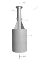
図1は本発明の一実施形態に係るバケット1の前方斜視図である。本実施形態のバケット1は、アースドリルのケリーバ等の回転体の下端に取り付けて地盤中の杭や、コンクリート構造物、礫、石等の障害物を撤去するのに用いることができる。
バケット1は、筒状(図示例では円筒状)のケーシング10と、ケーシング10の上部に一体的に設置される円筒状の内周面を有するガイド20と、ガイド20に挿通される略円筒状のシャフト30とを有する。ガイド20はケーシング10上面の中心の孔に挿通されている。ケーシング10の上面とガイド20の周面の間には複数(図示例では4つ)の補強板21が差し渡して取り付けてある。シャフト30はその上端において、例えばアースドリルのケリーバ等の回転体に対して同軸状に取り付けることが可能である。ガイド20とシャフト30とは軸方向および回転方向の各所定範囲内で相対移動可能である。図1はシャフト30がガイド20に対して最も上の位置にある状態を示している。図2はバケット1の別の前方斜視図であり、シャフト30がガイド20に対して最も下の位置にある状態を示している。図3は図1のバケットを横方向から見た図である。
FIG. 1 is a front perspective view of a
The
図4は図1のバケット1のケーシング10の前方の半分を透過的に示す部分透視図であり、図6は図1のバケット1のケーシング10の前方の半分を切断して示す部分切断図であり、図8は図3のバケット1のVIII-VIII切断図である。図5は図2のバケット1のケーシング10の前方の半分を透過的に示す部分透視図であり、図7は図2のバケット1のケーシング10の前方の半分を切断して示す部分切断図であり、図9は図8のバケット1のシャフト30を最も下の位置まで下げた場合の切断図である。なお、図8、9の切断図においてアーム41は表れないため、バケット1の前後方向に射影したアーム41の輪郭の位置を破線により示す。
これらの図に示す様に、ケーシング10の下部は開放されており、ケーシング10の内部には一対のアーム41、42と一対のシェル51、52が備えられる。図8、9に示す様に、シャフト30の下端付近にはその直径方向に1本のピン31が差し渡してあり、一対のアーム41、42のそれぞれの上端側である第1端部付近に設けられた第1孔41A、42Aがシャフト30の内側でピン31に遊嵌されることで、一対のアーム41、42はシャフト30の下部に対して回動可能に連結されている。一対のアーム41、42の第1端部とは反対の第2端部付近にはそれぞれ第2孔41B、42Bが設けられ、一対のシェル51、52のそれぞれの上縁部(すなわち、上側の縁部)付近に設けられたピン51A、52Aのそれぞれに対して遊嵌されている。これにより、一対のアーム41、42の第2端部は一対のシェル51、52の上縁部付近に対してそれぞれ回動可能に連結される。ピン51A、52Aは一対のシェル51、52のそれぞれの内周面に立設された板状部材に固定されている。
4 is a partial perspective view transparently showing the front half of the
As shown in these figures, the lower part of the
シャフト30の上端付近の外周にはガイド20の内径より大径のフランジ状の上部ストッパーS1が設けられている。シャフト30の下端付近の外周にはガイド20の内径より大径のフランジ状の下部ストッパーS2が設けられている。これらの上部ストッパーS1および下部ストッパーS2により、ガイド20に対するシャフト30の軸方向における相対的な移動可能範囲が規定される。
A flange-shaped upper stopper S1 having a diameter larger than the inner diameter of the
一対のシェル51、52のそれぞれは概ね、1/4球面状に形成されている。一対のシェル51、52のそれぞれは、長手方向の両端部にそれぞれ孔を有する。ケーシング10は内周面から内側に突出し水平に対向し合う2本の支持突起11を有する。一方の支持突起11は一対のシェル51、52の一端側の孔の両方に挿入されており、他方の支持突起11は一対のシェル51、52の他端側の孔の両方に挿入されている。これにより一対のシェル51、52は、2本の支持突起11を支点として回動可能である。一対のアーム41、42がシャフト30のピン31周りを回動する軸と、一対のアーム41、42がシェル51、52のピン51A、52A周りを回動する軸と、一対のシェル51、52が2本の支持突起11周りを回動する軸は、図1~9に示す状態において互いに略平行である。
Each of the pair of
シャフト30が、その上端に取り付けられたケリーバ等によってガイド20に対して相対的に引き上げられるとき、一対のアーム41、42は上昇するとともに互いの間の角度が狭まり、一対のシェル51、52の上縁部同士を引き寄せるように動作する。そうすると、一対のシェル51、52は支持突起11を支点に回動し下縁部(すなわち、下側の縁部)同士が遠ざかるため、一対のシェル51、52の下縁部間は開くこととなる。一対のシェル51、52の下縁部同士が離れて開いている状態を、一対のシェル51、52の開状態と呼ぶこととし、特に図4、6、8に示す様に一対のシェル51、52の上縁部同士が接している状態を、一対のシェル51、52の全開状態と呼ぶこととする。
When the
反対に、シャフト30がケリーバ等によってガイド20に対して押し下げられるとき、一対のアーム41、42は下降するとともに互いの間の角度が広がり、一対のシェル51、52の上縁部同士を遠ざけるように動作する。そうすると、一対のシェル51、52は下縁部同士が接近するように回動し、図5、7、9に示す様に一対のシェル51、52の下縁部同士は最終的には互いに接触して閉じることとなる。このように一対のシェル51、52の下縁部同士が互いに接触して閉じている状態を、一対のシェル51、52の閉状態と呼ぶこととする。
On the contrary, when the
図1~9、特に図6、7に示す様に、シャフト30はその周面から外側に突出する係合突起32を有する。一方、ガイド20にはその周面を貫通する係合溝22が形成され、係合突起32は係合溝22に挿通されている。係合溝22はガイド20の軸方向に延びる軸方向溝22aと、軸方向溝22aの下端からガイド20の周方向一方側(例えば、上から見た場合の時計回りの方向)に伸びるシェル閉溝22bと、軸方向溝22aの上端からガイド20の周方向一方側に伸びるシェル開溝22cを有する。シャフト30がガイド20に対して軸方向に相対移動するとき、係合突起32は軸方向溝22a内を軸方向に移動する。係合突起32が軸方向溝22aの下端位置にあるときにシャフト30がケリーバ等によってガイド20に対して周方向一方側に所定程度(例えば、数度~十数度程度)回転させられると、係合突起32はシェル閉溝22b内に進入してこれと係合する。これにより、シャフト30とガイド20とは一対のシェル51、52を閉状態とする相対的な軸方向位置関係に保持される。係合突起32が軸方向溝22aの上端位置にあるときにシャフト30がケリーバ等によってガイド20に対して周方向一方側に所定程度(例えば、数度~十数度程度)回転させられると、係合突起32はシェル開溝22c内に進入しこれと係合する。これにより、シャフト30とガイド20とは一対のシェル51、52を全開状態とする相対的な軸方向位置関係に保持される。シェル閉溝22bまたはシェル開溝22cと係合突起32との係合を解消するには、ケリーバ等によってシャフト30をガイド20に対して周方向他方側(例えば、上から見た場合の反時計回りの方向)に回転させればよい。なお、上述した「周方向一方側」を、バケット1を上から見た場合の反時計回りの方向とし、「周方向他方側」を、バケット1を上から見た場合の時計回りの方向としてもよい。
As shown in FIGS. 1 to 9, particularly FIGS. 6 and 7, the
なお、一対のシェル51、52はケーシング10に軸支されており、ケーシング10に対して周方向には実質的に相対回転できない。そのため、シャフト30がガイド20に対して相対回転すると、シャフト30と一対のシェル51、52との間で捻りが生じることとなる。この点、一対のアーム41、42はシャフト30のピン31およびシェル51、52のピン51A、52Aに対して遊嵌されているため、上記のような捻りを実現できる。なお、一対のシェル51、52とケーシング10との間で周方向に相対回転可能な構成としてもよい。
The pair of
次に、本実施形態に係るバケット1を用いて掘削孔中の障害物を撤去する方法の例を主に図6、7に基づき説明する。ここでは、シャフト30の上端にアースドリルのケリーバが同軸状に取り付けられているものとして説明する。
掘削孔にバケット1を投入して内部の障害物を撤去する際には、まず、地上でケリーバによりシャフト30を引き上げて一対のシェル51、52を全開とする。そしてシャフト30をガイド20に対して周方向一方側に相対回転させ、係合突起32をシェル開溝22cに係合させ、一対のシェル51、52を全開状態に維持する。
Next, an example of a method of removing an obstacle in the excavation hole using the
When the
次に、ケリーバによりバケット1を持ち上げて、掘削孔内に降下させる。ケーシング10が障害物に貫入しケーシング10の内部に障害物が入ったときに降下を停止し、ケリーバにより周方向他方側へシャフト30を若干回転させ、係合突起32とシェル開溝22cとの係合を解消する。次に、ケリーバを降下させてシャフト30をガイド20に対して相対的に軸方向下方へ押し下げる。そのとき、係合突起32は軸方向溝22aを軸方向に下降する。そうすると、シャフト30の動きが一対のアーム41、42によって一対のシェル51、52に伝えられ、一対のシェル51、52は全開状態から閉じる方向へ支持突起11周りを回動する。こうして、一対のシェル51、52は、ケーシング10内の障害物を掬い取る。
Next, the
シャフト30の押し下げによって、最終的には図7に示す様に一対のシェル51、52は閉状態となる。このとき、一対のシェル51、52によって掬われた障害物は一対のシェル51、52とケーシング10とが形成する空間内に保持される。その状態でケリーバを周方向一方側へ所定程度回転させることで、係合突起32とシェル閉溝22bとを係合させる。その状態でケリーバを上昇させ、バケット1を地上まで持ち上げる。地上では、ケーシング10の底部を地表等に触れさせて、シャフト30をガイド20に対して周方向他方側へ回転させて係合突起32とシェル閉溝22bとの係合を解消する。ケリーバによりシャフト30を持ち上げることで一対のシェル51、52は開状態となり、内部に保持していた障害物はケーシング10の下方から排出される。そして、以上の一連の動作を繰り返し行う。
By pushing down the
本実施形態のバケット1によれば、一対のシェル51、52を全開とすると、一対のシェル51、52は支持突起11よりも上側に位置し、内周面を下方に向けた状態となるので、それらの下側に大きなケーシング10の内部空間を画定することができる。そのため、その状態でケーシング10を下方に押し込むことで、下方から大量の土砂や障害物片を受け入れることができる。また、一対のシェル51、52に対して一対のアーム41、42により上方向から力を加えることで一対のシェル51、52を閉じる方向へ作動させるため、一対のシェル51、52は掬い取る対象の土砂や障害物片に向かって行きながらそれらを掬い取ることとなる。更には、土砂や障害物片を掬った状態で、一対のシェル51、52を閉じた状態に保持することができる。以上により、一回当たり土砂の掘削や障害物の撤去における取りこぼし量が少なく、土砂の掘削や障害物の除去を効率的に行うことができる。
According to the
本実施形態のバケット1においては、一対のシェル51、52が支持突起11を介してケーシング10に軸支されている。そのため、一対のシェル51、52がケーシング10内で宙吊りにされる構成に比べて、一対のシェル51、52の姿勢が安定する。また、係合突起32がシェル閉溝22bまたはシェル開溝22cと係合しているときにケリーバからシャフト30に加えられる力が、一対のアーム41、42だけでなく、ケーシング10および支持突起11を介しても一対のシェル51、52に対して伝達される。そのため、ケリーバからの力が一対のシェル51、52に伝わり易く、しかも、一対のアーム41、42に要求される機械的強度を低減することができる。
In the
(変形例)
図10は本発明の変形例に係るバケットのガイド20’およびシャフト30の一部を取り出して示す図である。図10に示す様に、係合溝22は、一実施形態のシェル開溝22cに加えて、別のシェル開溝22dを有する。別のシェル開溝22dは、シェル閉溝22bとシェル開溝22cの間で、軸方向溝22aから周方向一方側へ伸びるものとすることができる。
このような構成によれば、例えば一対のシェル51、52の間に礫等が挟まった場合に一対のシェル51、52が完全に閉じることができずに所定程度開いた状態であっても、係合突起32を別のシェル開溝22dに係合させることで、一対のシェル51、52を所定程度開いた状態に安定的に維持することができる。シェル開溝の個数は図示のような2個に限らず、それ以上でもよい。
(Modification example)
FIG. 10 is a diagram showing a part of the guide 20'and the
According to such a configuration, for example, when gravel or the like is sandwiched between a pair of
(別の変形例)
図11は本発明の別の変形例に係るバケットのガイド20”およびシャフト30の一部を取り出して示す図である。図11に示す様に、一実施形態のシェル開溝22cに加えて、シェル閉溝22bと一体的に階段状の溝を形成する別のシェル開溝22eを備える。
このような構成によれば、例えば一対のシェル51、52の間に礫等が挟まった場合に一対のシェル51、52が完全に閉じることができずに所定程度開いた状態であっても、係合突起32を別のシェル開溝22eに係合させることで、一対のシェル51、52を所定程度開いた状態に安定的に維持することができる。別のシェル開溝22eは更に階段状に形成されていてもよい。
(Another variant)
FIG. 11 is a diagram showing a part of the
According to such a configuration, for example, when gravel or the like is sandwiched between a pair of
この発明は、上記発明の実施形態および変形例の説明に何ら限定されるものではない。特許請求の範囲の記載を逸脱せず、当業者が容易に想到できる範囲で種々の変形態様もこの発明に含まれる。 The present invention is not limited to the description of the embodiments and modifications of the above invention. Various modifications are also included in the present invention to the extent that those skilled in the art can easily conceive without departing from the description of the scope of claims.
1 バケット
10 ケーシング
11 支持突起
20、20’、20” ガイド
21 補強板
22 係合溝
22a 軸方向溝
22b シェル閉溝
22c、22d、22e シェル開溝
30 シャフト
31 ピン
32 係合突起
41、42 一対のアーム
41A、42A 第1孔
41B、42B 第2孔
51、52 一対のシェル
51A、52A ピン
S1 上部ストッパー
S2 下部ストッパー
1
Claims (3)
前記ケーシングの上部に一体的に設置されるガイドと、
前記ガイドに挿通されるシャフトと、
前記シャフトの下部に対して回動可能に連結される一対のアームと、
前記一対のアームの前記シャフトに対して回動可能に連結される部分とは反対側の部分に対してそれぞれ回動可能に連結される一対のシェルと、を備え、
前記一対のシェルは前記ケーシングの内面に対して回動可能に連結され、
前記シャフトは前記ガイドに対して上方から下方へ相対的に移動することで前記一対のアームを介して前記一対のシェルを開状態から閉状態へ変化させ、
前記シャフトは前記ガイドに対して下方から上方へ相対的に移動することで前記一対のアームを介して前記一対のシェルを閉状態から開状態へ変化させるバケットであって、
前記シャフトは周面から突出する係合突起を有し、
前記ガイドには前記係合突起が挿通される係合溝が形成され、
前記係合溝はシェル閉溝とシェル開溝を有し、
前記係合突起が前記シェル閉溝に係合するとき、前記シャフトと前記ガイドとは前記一対のシェルを閉状態とする相対的な位置関係に保持され、
前記係合突起が前記シェル開溝に係合するとき、前記シャフトと前記ガイドとは前記一対のシェルを開状態とする相対的な位置関係に保持される、バケット。 A tubular casing with an open bottom and
A guide that is integrally installed on the top of the casing,
The shaft inserted through the guide and
A pair of arms rotatably connected to the lower part of the shaft,
A pair of shells rotatably connected to a portion of the pair of arms opposite to the portion rotatably connected to the shaft of the pair of arms.
The pair of shells are rotatably connected to the inner surface of the casing and are rotatably connected.
The shaft moves relative to the guide from above to below to change the pair of shells from the open state to the closed state via the pair of arms.
The shaft is a bucket that changes the pair of shells from a closed state to an open state via the pair of arms by moving relative to the guide from below to above.
The shaft has an engaging protrusion protruding from the peripheral surface and has an engaging protrusion.
An engaging groove through which the engaging protrusion is inserted is formed in the guide.
The engaging groove has a shell closed groove and a shell open groove.
When the engaging protrusion engages with the shell closing groove, the shaft and the guide are held in a relative positional relationship that closes the pair of shells.
When the engaging protrusion engages with the shell open groove, the shaft and the guide are held in a relative positional relationship with the pair of shells open.
Priority Applications (1)
| Application Number | Priority Date | Filing Date | Title |
|---|---|---|---|
| JP2018041391A JP7055352B2 (en) | 2018-03-08 | 2018-03-08 | bucket |
Applications Claiming Priority (1)
| Application Number | Priority Date | Filing Date | Title |
|---|---|---|---|
| JP2018041391A JP7055352B2 (en) | 2018-03-08 | 2018-03-08 | bucket |
Publications (2)
| Publication Number | Publication Date |
|---|---|
| JP2019157379A JP2019157379A (en) | 2019-09-19 |
| JP7055352B2 true JP7055352B2 (en) | 2022-04-18 |
Family
ID=67992378
Family Applications (1)
| Application Number | Title | Priority Date | Filing Date |
|---|---|---|---|
| JP2018041391A Active JP7055352B2 (en) | 2018-03-08 | 2018-03-08 | bucket |
Country Status (1)
| Country | Link |
|---|---|
| JP (1) | JP7055352B2 (en) |
Families Citing this family (1)
| Publication number | Priority date | Publication date | Assignee | Title |
|---|---|---|---|---|
| JP7449545B2 (en) * | 2020-10-09 | 2024-03-14 | 東京テクノ株式会社 | Underground object crushing and removal equipment |
Citations (4)
| Publication number | Priority date | Publication date | Assignee | Title |
|---|---|---|---|---|
| JP2003090192A (en) | 2001-07-09 | 2003-03-28 | Katou Kenki Kk | Drilling bucket for earth drill |
| JP2005290941A (en) | 2004-03-31 | 2005-10-20 | Sanwa Kizai Co Ltd | Reverse enlarged head |
| US20150128458A1 (en) | 2013-09-17 | 2015-05-14 | Soilmec S.P.A. | Device for digging diaphragms |
| JP2017066709A (en) | 2015-09-30 | 2017-04-06 | 大容基功工業株式会社 | Underground continuous wall excavator and underground continuous wall excavation method |
Family Cites Families (3)
| Publication number | Priority date | Publication date | Assignee | Title |
|---|---|---|---|---|
| FR2300177A1 (en) * | 1975-02-06 | 1976-09-03 | France Etat | EXCAVATION CLAMP |
| JPH0640088U (en) * | 1992-11-06 | 1994-05-27 | 日本電信電話株式会社 | Electric pole foundation hole drilling equipment for boulders |
| JP3330850B2 (en) * | 1997-06-16 | 2002-09-30 | 大商新基株式会社 | Expansion device |
-
2018
- 2018-03-08 JP JP2018041391A patent/JP7055352B2/en active Active
Patent Citations (4)
| Publication number | Priority date | Publication date | Assignee | Title |
|---|---|---|---|---|
| JP2003090192A (en) | 2001-07-09 | 2003-03-28 | Katou Kenki Kk | Drilling bucket for earth drill |
| JP2005290941A (en) | 2004-03-31 | 2005-10-20 | Sanwa Kizai Co Ltd | Reverse enlarged head |
| US20150128458A1 (en) | 2013-09-17 | 2015-05-14 | Soilmec S.P.A. | Device for digging diaphragms |
| JP2017066709A (en) | 2015-09-30 | 2017-04-06 | 大容基功工業株式会社 | Underground continuous wall excavator and underground continuous wall excavation method |
Also Published As
| Publication number | Publication date |
|---|---|
| JP2019157379A (en) | 2019-09-19 |
Similar Documents
| Publication | Publication Date | Title |
|---|---|---|
| JP6016998B1 (en) | Existing pile removal device | |
| JP4699304B2 (en) | Widened bucket | |
| JP6099955B2 (en) | Nakabori excavator | |
| JP5265642B2 (en) | Buried material removal device | |
| JP7055352B2 (en) | bucket | |
| JP4838215B2 (en) | Method and apparatus for excavating cast-in-place concrete joint pile | |
| JP2010528204A (en) | Hammerbit | |
| JP3818519B2 (en) | Drilling tool for earth drill | |
| JP6387503B2 (en) | Bucket equipment | |
| JP6152274B2 (en) | Expanded bucket | |
| JP3145827U (en) | Medium digging equipment | |
| JP4638898B2 (en) | Hammer grab | |
| JP5380574B2 (en) | Bucket, casing, and pile construction method | |
| CN215718497U (en) | A dig and get device that is used for drily boring of loess layer to dig | |
| JP2001193377A (en) | Drilling equipment for press-fit steel pipes | |
| JP7104571B2 (en) | Underground obstacle removal device | |
| JP6329382B2 (en) | Excavation bucket and excavation method | |
| JP7449545B2 (en) | Underground object crushing and removal equipment | |
| JP2023008062A (en) | Bucket device for earth drill | |
| JP4599213B2 (en) | Drilling device and drilling method using the same | |
| CN205000379U (en) | Dig grab bucket of quick -witted guide arm formula of stake soon | |
| KR20200064483A (en) | Bit for enlarging excavation hole | |
| JP5873679B2 (en) | Drilling bucket and excavation method using drilling bucket | |
| JP2012020869A (en) | Grab bucket | |
| JP3798794B2 (en) | Existing pile extraction device and method |
Legal Events
| Date | Code | Title | Description |
|---|---|---|---|
| A621 | Written request for application examination |
Free format text: JAPANESE INTERMEDIATE CODE: A621 Effective date: 20210126 |
|
| A977 | Report on retrieval |
Free format text: JAPANESE INTERMEDIATE CODE: A971007 Effective date: 20211222 |
|
| A131 | Notification of reasons for refusal |
Free format text: JAPANESE INTERMEDIATE CODE: A131 Effective date: 20220202 |
|
| A521 | Request for written amendment filed |
Free format text: JAPANESE INTERMEDIATE CODE: A523 Effective date: 20220215 |
|
| TRDD | Decision of grant or rejection written | ||
| A01 | Written decision to grant a patent or to grant a registration (utility model) |
Free format text: JAPANESE INTERMEDIATE CODE: A01 Effective date: 20220329 |
|
| A61 | First payment of annual fees (during grant procedure) |
Free format text: JAPANESE INTERMEDIATE CODE: A61 Effective date: 20220330 |
|
| R150 | Certificate of patent or registration of utility model |
Ref document number: 7055352 Country of ref document: JP Free format text: JAPANESE INTERMEDIATE CODE: R150 |
|
| R250 | Receipt of annual fees |
Free format text: JAPANESE INTERMEDIATE CODE: R250 |