JP7190848B2 - Frame and method for manufacturing frame - Google Patents
Frame and method for manufacturing frame Download PDFInfo
- Publication number
- JP7190848B2 JP7190848B2 JP2018169599A JP2018169599A JP7190848B2 JP 7190848 B2 JP7190848 B2 JP 7190848B2 JP 2018169599 A JP2018169599 A JP 2018169599A JP 2018169599 A JP2018169599 A JP 2018169599A JP 7190848 B2 JP7190848 B2 JP 7190848B2
- Authority
- JP
- Japan
- Prior art keywords
- frame
- vertical
- vertical frame
- horizontal
- adhesive member
- Prior art date
- Legal status (The legal status is an assumption and is not a legal conclusion. Google has not performed a legal analysis and makes no representation as to the accuracy of the status listed.)
- Active
Links
Images


Landscapes
- Joining Of Corner Units Of Frames Or Wings (AREA)
- Wing Frames And Configurations (AREA)
Description
本発明は、枠体及び枠体の製造方法に関する。 The present invention relates to a frame and a method for manufacturing the frame.
従来、一対の縦枠と、上枠と、下枠とを方形状に連結した樹脂製の枠体が知られている(例えば、特許文献1参照)。特許文献1に記載の枠体は、各枠の長手方向の端部を45度に切断加工し、切断した端面を突き合わせて、熱溶着により圧着して連結することによって構成されている。
2. Description of the Related Art Conventionally, there has been known a frame made of resin in which a pair of vertical frames, an upper frame, and a lower frame are connected in a rectangular shape (see, for example, Patent Document 1). The frame body described in
ところで、外観向上の目的で、枠体(障子)の基材の表面を基材とは異なる色の表層部材で覆った枠体が知られている。このような枠体を溶着して接合する際、特許文献1に示すように、各枠同士を突き合せて熱溶着により圧着して連結する。このとき、熱溶着の際、枠同士の接合面から内側の基材及び表層部材が盛り上がり、枠体の表面にはバリが発生する。このバリを除去すると、枠間には基材が露出してしまう。基材の色と表層部材の色とが異なるため、露出した基材を表層部材と同じ色に塗装する必要が生じる。露出部分の塗装は人の手で行われるため、工数や資材費が掛かり、生産効率が低下してしまう。
By the way, for the purpose of improving the appearance, there is known a frame body (shoji) in which the surface of the base material of the frame body (shoji) is covered with a surface layer member having a color different from that of the base material. When such frames are welded and joined, as shown in
本発明は、このような問題点に鑑みてなされたものであって、生産効率を向上可能な枠体及び枠体の製造方法の提供を目的とする。 The present invention has been made in view of such problems, and an object of the present invention is to provide a frame and a method for manufacturing the frame that can improve production efficiency.
本発明に係る枠体は、上下方向に延びる一対の縦枠及び一対の前記縦枠と直交する方向に延びる一対の横枠を四方枠状に連結してなり、前記縦枠及び前記横枠は、基材と、前記基材の表面に形成され前記基材とは異なる色の表層部材と、を有し、前記縦枠と前記横枠とは、前記表層部材と同色であって熱溶着された接着部材を介して連結されていることを特徴とする。 A frame according to the present invention is formed by connecting a pair of vertically extending vertical frames and a pair of horizontal frames extending in a direction orthogonal to the pair of vertical frames in a four-sided frame shape, wherein the vertical frames and the horizontal frames are , a base material, and a surface layer member formed on the surface of the base material and having a color different from that of the base material, and the vertical frame and the horizontal frame have the same color as the surface layer member and are heat-welded. characterized by being connected via an adhesive member.
本発明では、縦枠と横枠とは、表層部材と同色の接着部材を介して連結されているため、基材が縦枠と横枠との間から露出することを防止することができる。すなわち、接着部材が縦枠と横枠との間に露出しているため、従来のように、露出した基材を表層部材と同じ色で塗る必要がない。これにより、生産効率を向上させることができる。また、本発明によれば、露出した基材を表層部材と同じ色で塗る必要がないため、色ムラの発生や枠体ごとの色のバラつきを抑えることができる。従って、品質を向上させることが可能となる。 In the present invention, since the vertical frame and the horizontal frame are connected via the adhesive member of the same color as the surface layer member, it is possible to prevent the base material from being exposed between the vertical frame and the horizontal frame. That is, since the adhesive member is exposed between the vertical frame and the horizontal frame, it is not necessary to paint the exposed base material with the same color as the surface layer member as in the conventional art. Thereby, production efficiency can be improved. Moreover, according to the present invention, since it is not necessary to paint the exposed base material with the same color as the surface layer member, it is possible to suppress the occurrence of color unevenness and variations in the color of each frame. Therefore, quality can be improved.
また、本発明に係る枠体において、前記縦枠または前記横枠は内部に中空部を有し、前記接着部材は、前記表層部材に沿って延びる第1延在部と、前記第1延在部に直交して延びるとともに、前記縦枠及び前記横枠の板厚よりも厚い第2延在部とを有していてもよい。 Further, in the frame body according to the present invention, the vertical frame or the horizontal frame has a hollow portion inside, and the adhesive member includes a first extension portion extending along the surface layer member and the first extension portion. It may have a second extending portion that extends perpendicularly to the portion and is thicker than the plate thickness of the vertical frame and the horizontal frame.
縦枠及び前記横枠の板厚よりも厚い第2延在部第2延在部を有しているため、縦枠と横枠との接触面積を大きくすることができる。従って、縦枠と横枠とをより強固に接着することができる。 Since the vertical frame and the horizontal frame have the second extension portion thicker than the plate thickness of the horizontal frame, the contact area between the vertical frame and the horizontal frame can be increased. Therefore, the vertical frame and the horizontal frame can be adhered more firmly.
また、本発明に係る枠体において、前記縦枠または前記横枠の少なくとも一方の端面には、前記表層部材よりも前記縦枠または前記横枠の内部側に形成されるとともに、隣接する前記縦枠または前記横枠の他方側に向かって突出する段部が設けられ、前記接着部材は前記段部を覆うように設けられていてもよい。 Further, in the frame according to the present invention, at least one end surface of the vertical frame or the horizontal frame is formed closer to the inner side of the vertical frame or the horizontal frame than the surface layer member, and the adjacent vertical frame is formed on the inner side of the vertical frame or the horizontal frame. A stepped portion projecting toward the other side of the frame or the horizontal frame may be provided, and the adhesive member may be provided so as to cover the stepped portion.
段部を覆うように接着部材が設けられているため、表層部材の表面からの基材の露出をより効果的に抑えることが可能となる。 Since the adhesive member is provided so as to cover the stepped portion, it is possible to more effectively suppress exposure of the base material from the surface of the surface layer member.
また、本発明に係る枠体において、前記縦枠と前記横枠とを突き当てて形成された角部の外周側において、前記縦枠または前記横枠のうち少なくとも一方の端部には、側部と、底部と、を有する凹状の切欠き部が形成され、前記切欠き部には、前記接着部材が設けられ、前記側部は前記縦枠または前記横枠のうちの他方と連結されていてもよい。 Further, in the frame body according to the present invention, on the outer peripheral side of the corner formed by abutting the vertical frame and the horizontal frame, at least one end of the vertical frame or the horizontal frame has a side A recessed cutout portion having a portion and a bottom portion is formed, the cutout portion is provided with the adhesive member, and the side portion is connected to the other of the vertical frame or the horizontal frame. may
切欠部に接着部材が配置されているため、枠体の側面においても基材の露出を抑えることができる。従って、露出部分に色付けする手間が省ける。また、枠体の角部から接着部材がはみ出すのを抑えることができるため、資材費を抑えることができる。 Since the adhesive member is arranged in the notch, exposure of the base material can be suppressed even on the side surfaces of the frame. Therefore, the trouble of coloring the exposed portion can be saved. In addition, since it is possible to prevent the adhesive member from protruding from the corners of the frame, material costs can be reduced.
本発明に係る枠体の製造方法において、上下方向に延びる一対の縦枠及び一対の前記縦枠と直交する方向に延びる一対の横枠とを四方枠状に連結してなり、前記縦枠及び前記横枠は、基材と、前記基材の表面に形成され前記基材とは異なる色の表層部材と、を有し、
前記縦枠と前記横枠とを、前記表層部材と同色の接着部材を介して連結した枠体の製造方法であって、隣接する前記縦枠または前記横枠の少なくとも一方の端面に前記接着部材を配置する接着部材配置工程と、前記縦枠及び前記横枠の端面を加熱する加熱工程と、前記縦枠と前記横枠とを当接し、圧着して前記縦枠と前記横枠とを溶着して連結する連結工程と、を備える。
In the method for manufacturing a frame according to the present invention, a pair of vertical frames extending in the vertical direction and a pair of horizontal frames extending in a direction orthogonal to the pair of vertical frames are connected to form a four-sided frame, and the vertical frames and The horizontal frame has a base material and a surface layer member formed on the surface of the base material and having a color different from that of the base material,
A method for manufacturing a frame in which the vertical frame and the horizontal frame are connected via an adhesive member having the same color as that of the surface layer member, wherein the adhesive member is attached to at least one end face of the adjacent vertical frame or the horizontal frame. a heating step of heating the end surfaces of the vertical frame and the horizontal frame; and the vertical frame and the horizontal frame are brought into contact and crimped to weld the vertical frame and the horizontal frame. and a connecting step of connecting by
この場合、隣接する縦枠または横枠の少なくとも一方の端面に接着部材を配置し、縦枠及び横枠の端面を加熱して縦枠及び横枠を圧着して連結する際、縦枠と横枠との間から接着部材がはみ出る。表層部材と同色の接着部材を縦枠または横枠の少なくとも一方の端面に配置することにより、はみ出した部分(バリ)を切除しても、表層部材と同色の接着部材が残るため、基材は露出しない。これにより、基材を塗装するコストと手間を省くことができるため、生産効率を向上させることができる。 In this case, when the adhesive member is placed on at least one end surface of the adjacent vertical frame or horizontal frame and the end surfaces of the vertical frame and the horizontal frame are heated to crimp and connect the vertical frame and the horizontal frame, The adhesive member protrudes from between the frames. By placing an adhesive member of the same color as the surface layer member on at least one end face of the vertical frame or the horizontal frame, even if the protruding portion (burr) is cut off, the adhesive member of the same color as the surface layer member remains. not exposed. As a result, it is possible to save the cost and labor of coating the base material, so that the production efficiency can be improved.
また、本発明に係る枠体の製造方法では、前記接着部材配置工程において、前記縦枠の両端面及び前記横枠の両端面に前記接着部材を設置してもよい。
この場合、より均一、かつ、安定した状態で縦枠と横枠とを接着させることができる。
Further, in the method for manufacturing a frame according to the present invention, in the step of arranging adhesive members, the adhesive members may be provided on both end surfaces of the vertical frame and both end surfaces of the horizontal frame.
In this case, the vertical frame and the horizontal frame can be adhered in a more uniform and stable state.
また、本発明に係る枠体の製造方法では、前記縦枠または前記横枠の少なくとも一方の端面には、前記基材の表面よりも前記縦枠または前記横枠の内部側に形成されるとともに、隣接する前記縦枠または前記横枠の他方側に向かって突出する段部が設けられ、前記接着部材には、前記段部に当接可能な窪みが形成され、前記接着部材配置工程において、前記接着部材の前記窪みが、前記段部を覆うように設けられていてもよい。 Further, in the frame manufacturing method according to the present invention, at least one end surface of the vertical frame or the horizontal frame is formed on the inner side of the vertical frame or the horizontal frame rather than the surface of the base material. , a step portion protruding toward the other side of the adjacent vertical frame or the horizontal frame is provided, the adhesive member is formed with a recess capable of coming into contact with the step portion, and in the step of arranging the adhesive member, The recess of the adhesive member may be provided so as to cover the stepped portion.
この場合には、段部に窪みを当接させることにより、段部の上面には必ず接着部材が配置される。これにより、表層部材の表面からの基材の露出を確実に抑えることができる。また、段部に窪みを当接させることにより、一定の位置に接着部材を配置させることができる。 In this case, by bringing the recess into contact with the stepped portion, the adhesive member is always arranged on the upper surface of the stepped portion. Thereby, exposure of the base material from the surface of the surface layer member can be reliably suppressed. Also, by bringing the recess into contact with the stepped portion, the adhesive member can be arranged at a fixed position.
本発明の枠体及び枠体の製造方法によれば、生産効率を向上させることができる。 According to the frame body and the method for manufacturing the frame body of the present invention, production efficiency can be improved.
[第1実施形態]
本発明の一実施形態に係る障子(枠体)10について、図1から図14を参照して説明する。
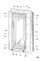
図1に示すように、本実施形態に係る建具1は、例えば、辷り出し窓であり、壁部2に形成された開口部に設けられている。建具1は、開口部に沿って設けられた四方枠状の開口枠体40と、開口枠体40の内側に室内外方向に開閉可能に設けられた障子10とを備えている。
本実施形態においては、建具1に設けられた障子10を用いて説明を行うが、本願発明は辷り出し窓に限られず、引違い窓、開き窓などに使用される障子や開口枠体にも適用可能である。
以下の説明において、室外側と室内側とを結ぶ方向を室内外方向とし、壁部2に取り付けられた建具1を室内側から見たときに、上下となる方向を上下方向、左右となる方向を左右方向とする。
[First embodiment]
A shoji (frame body) 10 according to an embodiment of the present invention will be described with reference to FIGS. 1 to 14. FIG.
As shown in FIG. 1,
In this embodiment, the
In the following description, the direction connecting the outdoor side and the indoor side is defined as the indoor/outdoor direction, and when the
開口枠体40は、左右方向に延びる上枠41及び下枠42と、上下方向に延びて上枠41及び下枠42と連結された一対の縦枠43,44とを有している。上枠41、下枠42、及び一対の縦枠43,44は、略同じ断面に形成されている。上枠41の両端部41a,41b、下枠42の両端部42a,42b、及び縦枠43の両端部43a,43b、縦枠44の両端部44a,44bは、それぞれ斜め45°に切断されている。上枠41及び下枠42と、一対の縦枠43,44とは、互いの端部を突き合わせて90°をなすように連結されている。
The
障子(枠体)10は、図1及び図2に示すように、それぞれ四方枠状に形成された框体11と、框体11内に配置されて框体11によって支持された複層ガラス12とを有している。
As shown in FIGS. 1 and 2, the shoji (frame body) 10 includes a
框体11は、上下方向に延びる戸先側縦框(縦枠)13,吊元側縦框(縦枠)14と、戸先側縦框13の上端部13aと吊元側縦框14の上端部14aとを連結する上框15と、戸先側縦框13の下端部13bと吊元側縦框14の下端部14bとを連結する下框16とを備えている。上框15及び下框16は、左右方向に延びている。
図2に示すように、戸先側縦框13、吊元側縦框14、上框15及び下框16は、それぞれ基材13A、14A、15A、16Aと、表層部材20と、を有している。例えば、図3に示すように、戸先側縦框13は、基材13Aと表層部材20とを有し、上框15は、基材15Aと表層部材20とを有している。
図1に示すように、戸先側縦框13には、室内側にレバーハンドル6が設けられている。レバーハンドル6は、障子10に設けられた施錠機構(不図示)の施錠状態と解錠状態とを切り替えるように構成されている。
The
As shown in FIG. 2, the door end side
As shown in FIG. 1, the
図2に示すように、上框15、下框16、戸先側縦框13及び吊元側縦框14は、それぞれ同じ断面に形成されている。上框15の両端部15a,15b、下框16の両端部16a,16b、戸先側縦框13の両端部13a,13b及び吊元側縦框14の両端部14a,14bはそれぞれ斜め45°に切断されている。上框15の端部15aと戸先側縦框13の端部13aとを突き合わせて90°をなすように、接着部材30が介在された状態で連結されている。同様に上框15の端部15bと吊元側縦框14の端部14aとを突き合わせて、吊元側縦框14の端部14bと下框16の端部16bとを突き合わせて、下框16の端部16aと戸先側縦框13の端部13bとを突き合わせて、90°をなすように、接着部材30がそれぞれ介在された状態で連結されている。このようにして、框体11が四方枠状に形成されている。
As shown in FIG. 2, the
図3に示すように、外観の向上の目的から、基材13A及び基材15Aの室外側の表面11aは表層部材20で覆われている。すなわち、上框15を構成する基材15A、下框16を構成する基材16A、戸先側縦框13を構成する基材13A及び吊元側縦框14を構成する基材14Aのそれぞれの表面11aは、表層部材20で覆われている。表層部材20は、例えば、アクリル樹脂である。本実施形態では、各基材13A~16Aと、表層部材20との2層の押出成形により、基材13A~基材16Aの表面11aに表層部材20が形成されて、上框15、下框16、戸先側縦框13及び吊元側縦框14が形成されている。表層部材20は、少なくとも基材13A~基材16Aの表面11aを覆っていればよい。本実施形態では、表層部材20は、基材13A~基材16Aの表面11a及び側面11bを覆っている。
各框を構成する基材13A~基材16Aは、表層部材20と異なる色によって形成されている。本実施形態では、基材13A~16Aは、例えば白色であり、表層部材20は、黒色である。
接着部材30は、表層部材20と同じ色によって形成されている。すなわち、本実施形態においては、接着部材30は黒色である。なお、表層部材20と接着部材30との色が同じ色であればよいため、基材13A~16A、表層部材20、接着部材30の色は任意である。
As shown in FIG. 3, the
The
The
次に、各框同士の連結構造は同じであるため、戸先側縦框13と上框15との連結部分について説明する。
図3に示すように、各上框15、下框16、戸先側縦框13及び吊元側縦框14は、中空部S2を有している。図3及び図4に示すように、接着部材30は、表層部材20に沿って延びる第1接着部(第1延在部)31と、障子10の側面10bに沿って延びる突出部32と、第1接着部31に直交して延びる第2接着部(第2延在部)38と、中空部S2に挿入される第1片33及び第2片34とを有している。接着部材30は、第1接着部31と突出部32とにより、L字状に形成されている。接着部材30の第1接着部31は、障子10の表面10a側に露出している。接着部材30の突出部32は、障子10の側面10b側に露出している。
Next, since the connecting structure between the frames is the same, the connecting portion between the front side
As shown in FIG. 3, each of the
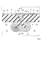
図5に示すように、戸先側縦框13の端面13cには、表層部材20よりも戸先側縦框13の内側に形成されるとともに、隣接する上框15の端面15c側に向かって突出する段部17が設けられている。同様に、上框15の端面15cには、表層部材20よりも上框15の内側に形成されるとともに、隣接する戸先側縦框13の端面13cに向かって突出する段部18が設けられている。接着部材30は段部17及び段部18を覆うように設けられている。すなわち、第1接着部31は、戸先側縦框13と上框15との間の、戸先側縦框13の段部17と上框15の段部18とによって形成される空間S1内に充填されており、段部17の上面17a及び段部18の上面18aに、第1接着部31が配置されている。第1接着部31は、表層部材20と略面一になる位置まで設けられている。さらに、第1接着部31は、戸先側縦框13の段部17を形成する突起部17bと、上框15の段部18を形成する突起部18bとの間から戸先側縦框13の下面13d及び上框15の下面15dまで設けられている。すなわち、第1接着部31は、戸先側縦框13と上框15との間において、表層部材20から戸先側縦框13及び上框15の内部に形成された中空部S2まで達し、戸先側縦框13と上框15とを連結している。
As shown in FIG. 5 , on the
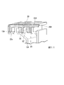
図4に示すように、各框13~16を突き当てて形成された角部の外周側において、戸先側縦框13の端部13fには、側部131と底部132とを有する凹状の切欠部13eが形成されている。切欠部13eは、室内外方向に沿って戸先側縦框13及び表層部材20を切り欠いた部分である。突出部32は、戸先側縦框13の切欠部13eに配置されている。同様に、戸先側縦框13に対向して配置される上框15にも、側部151と底部152とを有する凹状の切欠部15eが形成され、突出部32は、上框15の切欠部15eに配置されている。これにより、室内外方向(厚み方向)においても、戸先側縦框13と上框15との間には突出部32が介在された状態で、戸先側縦框13と上框15とが連結されている。また、戸先側縦框13の側部131は、上框15の側部151と連結されている。
As shown in FIG. 4, on the outer peripheral side of the corner formed by abutting each of the
次に、本発明に係る枠体の製造方法について、図6から図14を参照して説明する。
まず、連結前の框体11及び接着部材30Aの構成について説明する。各框の端部の構造は同じであるため、戸先側縦框13を例に挙げて説明する。
図6に示すように、戸先側縦框13には、両端部13a,13bに沿って段部17が形成されている。段部17は、表層部材20及び戸先側縦框13を内側に(厚み方向に)切り欠かれることによって形成されている。段部17の突出寸法は、数ミリ程度である。
図7に示すように、戸先側縦框13の側面の端部13fには、切欠部13eが形成されている。切欠部13eは、戸先側縦框13の側面の端部13fの室内外方向における中央部分を含んだ位置に形成されている。すなわち、戸先側縦框13の側面の端部13fの上部及び下部(側部)131を残して切り欠かれている。
Next, a method for manufacturing a frame according to the present invention will be described with reference to FIGS. 6 to 14. FIG.
First, the structure of the
As shown in FIG. 6, a
As shown in FIG. 7, a
次に、框間に介在させる接着部材30Aについて説明する。
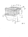
図8に示すように、溶着前の接着部材30Aは、第1接着部31Aと、第1接着部31Aに直交する方向に延びる突出部32Aと、第1片33及び第2片34とを備えている。また、図9に示すように、第1片33及び第2片34は、突出部32Aの延在方向に延びるとともに、第1接着部31A及び突出部32Aの延在方向に直交する方向に突出する板状部材である。また、第1片33及び第2片34は、第1接着部31の延在方向に沿って間隔をあけて設けられている。
さらに、接着部材30Aには、第1接着部31A及び突出部32Aの延在方向に直交する方向に突起した突起部35が設けられている。突起部35は、第1接着部31Aの上部に第1接着部31Aの延在方向に沿って延びている。突起部35は、第1片33及び第2片34と間隔をあけて設けられている。これにより、突起部35と第1片33及び第2片34との間には窪み36が形成される。この窪み36は、戸先側縦框13に形成された段部17に当接(載置)可能である。
Next, the
As shown in FIG. 8, the
Furthermore, the
また、図7に示すように、各框には、内部に中空部S2が形成されている。中空部S2の室内外方向における寸法をL1とし、図9に示すように、第1片33及び第2片34の延在方向の寸法をL2とすると、中空部の寸法L1と第1片33及び第2片34の寸法L2とは、ほぼ同じか、若干第1片33及び第2片34の寸法L2の方が大きく形成されている。これにより、第1片33及び第2片34は中空部S2に篏合可能な構成となっている。
また、図7に示すように、切欠部13eの室内外方向における寸法をL3とし、図9に示すように、突出部32Aの延在方向における寸法をL4とすると、突出部32Aの寸法L4の方が小さく形成されている。これにより、接着部材30Aを溶着した際、接着部材30Aが切欠部13eに埋まるように構成されている。
Further, as shown in FIG. 7, each frame has a hollow portion S2 formed therein. Assuming that the dimension of the hollow portion S2 in the indoor/outdoor direction is L1 and the dimension in the extending direction of the
Assuming that the dimension of the
図10に示すように、戸先側縦框13の端部13aに、上述した接着部材30Aを配置する(接着部材配置工程)。このとき、接着部材30Aの窪み36が段部17に当接し、戸先側縦框13の切欠部13eに接着部材30Aの突出部32Aは配置される。
図10及び図13に示すように、接着部材30Aにおいて、戸先側縦框13及び上框15の板厚の寸法L5に比べて、接着部材30Aの第2接着部38の厚みの寸法L6の方が厚く形成されている。また、図11に示すように、第1片33及び第2片34が中空部S2に入り込み、接着部材30Aと戸先側縦框13とが篏合する。
As shown in FIG. 10, the
As shown in FIGS. 10 and 13, in the
戸先側縦框13の端部13aと同様に、戸先側縦框13の端部13b、上框15の両端部15a,15b、下框16の両端部16a,16b、戸先側縦框13の両端部13a,13b及び吊元側縦框14の両端部14a,14bそれぞれに接着部材30を配置した後、図12に示すように、上框15の両端部15a,15b、下框16の両端部16a,16b、戸先側縦框13の両端部13a,13b及び吊元側縦框14の両端部14a,14bをそれぞれ対向させて配置する。隣接する接着部材30A間に加熱した熱板(図示略)を挟み、接着部材30A及び各上框15,下框16,戸先側縦框13,吊元側縦框14の端面を溶融させる(加熱工程)。その後、図13に示すように、戸先側縦框13の端部13aと上框15の端部15aとを突き合わせて圧着する。他の端部においても同様に突き合わせて圧着して、上框15,下框16,戸先側縦框13,吊元側縦框14同士を溶着して連結する(連結工程)。このとき、図14に示すように、表層部材20の表面20aからは接着部材30がはみ出し、バリ37が発生する。バリ37は、カッター装置などを用いて、接着部材30が表層部材20の表面20aと略面一となるように除去され、接着部材30が介在された状態で框同士が連結される。
Similarly to the
本実施形態の障子10では、4つの角部である隣接する上框15と戸先側縦框13との間、戸先側縦框13と下框16との間、下框16と吊元側縦框14との間、吊元側縦框14と上框15との間に接着部材30が介在された状態で上框15,下框16,戸先側縦框13,吊元側縦框14同士が連結されている。これにより、白色の框体11が表層部材20の表面20aから露出することを防止することができる。すなわち、接着部材30が上框15,下框16,戸先側縦框13,吊元側縦框14間に露出しているため、従来のように、露出した框体11の白色部分を表層部材20と同じ黒色で塗る必要がない。従って、生産効率を向上させることができ、さらには、色ムラの発生や枠体ごとの色のバラつきを抑えることができるので、品質を向上させることが可能となる。
In the
また、本実施形態では、室内外方向に沿って延びる突出部32を有しているため、角部分にバリが出ないように形成した切欠部13eを埋めることができる。
接着部材30Aにおいて、基材13Aの板厚の寸法L5に比べて、接着部材30Aの第2接着部38の厚みの寸法L6の方が厚く形成されているため、第2接着部38は、図14に示すように、基材13A~基材16Aの下面に回り込む。これにより、隣接する框間の接合面積が広くなるので、接着強度が増すことになり、框間同士が強固に連結される。
Further, in the present embodiment, since the projecting
In the
本実施形態では、段部17の上面17aに接着部材30が載置されているため、表層部材20の表面20aからの框体11の露出をより効果的に抑えることが可能となる。
In this embodiment, since the
また、本実施形態では、切欠部13eに接着部材30が配置されているため、障子10の側面10bにおいても、白色の框体11の露出を抑えることができる。従って、露出部分に色付けする手間が省ける。また、障子10の角部から接着部材30がはみ出すのを抑えることができるため、資材費を抑えることができる。
Moreover, in this embodiment, since the
本実施形態の障子10の製造方法では、隣接する上框15の両端部15a,15b、下框16の両端部16a,16b、戸先側縦框13の両端部13a,13b及び吊元側縦框14の両端部14a,14bに配置された接着部材30を加熱して框同士を圧着して連結すると、上框15,下框16,戸先側縦框13,吊元側縦框14間から接着部材30がはみ出る。表層部材20と同色の接着部材30を框の両端部に配置するため、はみ出した部分(バリ)を切除しても、表層部材20と同色の接着部材30が残るので、白色の框体11は露出しない。これにより、従来のように框間に露出した白色部分を塗装するコストと手間を省くことができるため、生産効率を向上させることができる。
また、隣接する上框15の両端部15a,15b、下框16の両端部16a,16b、戸先側縦框13の両端部13a,13b及び吊元側縦框14の両端部14a,14bのそれぞれに接着部材30を配置しているため、より均一、かつ、安定した状態で框同士を接着させることができる。
In the method for manufacturing the
Moreover, both ends 15a and 15b of the adjacent
本実施形態では、段部17に窪み36を当接させることにより、段部17の上面17aには必ず接着部材30Aが配置される。これにより、表層部材20の表面20aからの框体11の露出を確実に抑えることができる。また、段部17に窪み36を当接させることにより、一定の位置に接着部材30Aを配置させることができる。
さらに、接着部材30Aが、第1片33及び第2片34を有しているため、框同士をより強固に連結することができる。
In the present embodiment, the
Furthermore, since the
以上、本発明に係る枠体及び枠体の製造方法の実施形態について説明したが、本発明は上記の実施形態に限定されるものではなく、その趣旨を逸脱しない範囲で適宜変更可能である。本発明の趣旨を逸脱しない範囲で、構成の付加、省略、置換、およびその他の変更が可能である。本発明は前述した説明によって限定されることはなく、添付のクレームの範囲によってのみ限定される。 Although the embodiments of the frame and the method for manufacturing the frame according to the present invention have been described above, the present invention is not limited to the above-described embodiments, and can be modified as appropriate without departing from the scope of the invention. Configuration additions, omissions, substitutions, and other changes are possible without departing from the scope of the present invention. The present invention is not limited by the foregoing description, but only by the scope of the appended claims.
例えば、実施形態では、本発明の枠体として障子10を例に挙げて説明したが、開口枠体40においても同様に構成及び製造方法を適用することが可能である。すなわち、上枠41の端部41aと縦枠43の端部43aとの間、縦枠43の端部43bと下枠42の端部42aとの間、下枠42の端部42bと縦枠44の端部44bとの間、縦枠44の端部44aと上枠41の端部41bとの間に接着部材が介在された状態で、上枠41、下枠42、一対の縦枠43,44が連結されていてもよい。
また、表層部材20は、框体11の表面11a及び側面11bを覆っている構成としたが、少なくとも框体11の表面11aを覆っていればよい。
表層部材20は、框体11の室外側の表面11aに設けられた構成としたが、框体11の室内側の表面に表層部材20を設けてもよく、室内側と室外側の両方の表面に表層部材20が設けられていてもよい。
For example, in the embodiments, the
Further, the
Although the
また、接着部材30は、第1接着部31と第2接着部38とを有する構成としたが、少なくとも表層部材20を含む框体11の表面において、隣接する框間に接着部材30が介在された状態で、框同士が連結されていればよいため、第2接着部38は設けられていなくてもよい。また、第1片33、第2片34は、必ずしも設けられていなくてもよく、また、いずれか一方であってもよい。
また、各框に段部を設けていない構成であってもよい。各框が段部を設けていなくても各框間に接着部材を設けることにより框体11が障子10の表面10aから露出するのを防ぐことができる。
切欠部13eは必ずしも形成されていなくてもよい。
In addition, although the
Moreover, the structure which does not provide the step part in each frame may be sufficient. Even if each frame is not provided with a stepped portion, it is possible to prevent the
本実施形態では、各框の両端部に接着部材30を配置して溶着する方法を示したが、片側の端部にのみ接着部材30を配置して溶着する方法であってもよい。その場合、対向する框の端面のいずれか一方に接着部材30を配置すればよい。
In the present embodiment, the method of placing the
S1 中空部
10 障子(枠体)
11 框体(基材)
11a 框体の表面
13 戸先側縦框(縦枠)
13e 切欠部
14 吊元側縦框(縦枠)
15 上框(上枠)
16 下框(下枠)
17、18 段部
20 表層部材
30,30A 接着部材
31,31A 第1接着部(第1延在部)
38 第2接着部(第2延在部)
40 開口枠体(枠体)
S1
11 frame (base material)
11a surface of
15 Upper frame (upper frame)
16 lower frame (lower frame)
17, 18
38 second bonding portion (second extension portion)
40 opening frame (frame)
Claims (7)
前記縦枠及び前記横枠は、基材と、前記基材の表面に形成され前記基材とは異なる色の表層部材と、を有し、
前記縦枠と前記横枠とは、前記表層部材と同色であって熱溶着された接着部材を介して連結されていることを特徴とする枠体。 A pair of vertical frames extending in the vertical direction and a pair of horizontal frames extending in a direction orthogonal to the pair of vertical frames are connected in a quadrilateral frame shape,
The vertical frame and the horizontal frame have a base material and a surface layer member formed on the surface of the base material and having a color different from that of the base material,
A frame body, wherein the vertical frame and the horizontal frame are connected via an adhesive member of the same color as that of the surface layer member and thermally welded thereto .
前記接着部材は、前記表層部材に沿って延びる第1延在部と、前記第1延在部に直交して延びるとともに、前記縦枠及び前記横枠の板厚よりも厚い第2延在部とを有する請求項1に記載の枠体。 The vertical frame or the horizontal frame has a hollow inside,
The adhesive member includes a first extension portion extending along the surface layer member and a second extension portion extending perpendicular to the first extension portion and having a thickness greater than that of the vertical frame and the horizontal frame. The frame according to claim 1, comprising:
前記接着部材は前記段部を覆うように設けられる
請求項1または請求項2に記載の枠体。 At least one end surface of the vertical frame or the horizontal frame is formed on the inner side of the vertical frame or the horizontal frame than the surface layer member, and toward the other side of the adjacent vertical frame or the horizontal frame A stepped portion protruding from the
3. The frame according to claim 1, wherein said adhesive member is provided so as to cover said stepped portion.
前記縦枠または前記横枠のうち少なくとも一方の端部には、側部と、底部と、を有する凹状の切欠き部が形成され、
前記切欠き部には、前記接着部材が設けられ、
前記側部は前記縦枠または前記横枠のうちの他方と連結されている請求項1から3のいずれか一項に記載の枠体。 On the outer peripheral side of the corner formed by abutting the vertical frame and the horizontal frame,
At least one end of the vertical frame or the horizontal frame is formed with a recessed notch having a side and a bottom,
The adhesive member is provided in the notch,
4. The frame according to any one of claims 1 to 3, wherein said side portion is connected to the other of said vertical frame or said horizontal frame.
前記縦枠及び前記横枠は、基材と、前記基材の表面に形成され前記基材とは異なる色の表層部材と、を有し、
前記縦枠と前記横枠とを、前記表層部材と同色の接着部材を介して連結した枠体の製造方法であって、
隣接する前記縦枠または前記横枠の少なくとも一方の端面に前記接着部材を配置する接着部材配置工程と、
前記縦枠及び前記横枠の端面を加熱する加熱工程と、
前記縦枠と前記横枠とを当接し、圧着して前記縦枠と前記横枠とを溶着して連結する連結工程と、
を備える枠体の製造方法。 A pair of vertical frames extending in the vertical direction and a pair of horizontal frames extending in a direction orthogonal to the pair of vertical frames are connected in a quadrilateral frame shape,
The vertical frame and the horizontal frame have a base material and a surface layer member formed on the surface of the base material and having a color different from that of the base material,
A frame body manufacturing method in which the vertical frame and the horizontal frame are connected via an adhesive member having the same color as the surface layer member,
an adhesive member arranging step of arranging the adhesive member on at least one end face of the adjacent vertical frame or horizontal frame;
a heating step of heating end surfaces of the vertical frame and the horizontal frame;
A connection step of contacting the vertical frame and the horizontal frame and crimping them to weld and connect the vertical frame and the horizontal frame;
A method for manufacturing a frame comprising:
請求項5に記載の枠体の製造方法。 6. The method of manufacturing a frame according to claim 5, wherein in the step of arranging the adhesive members, the adhesive members are installed on both end surfaces of the vertical frame and both end surfaces of the horizontal frame.
前記接着部材には、前記段部に当接可能な窪みが形成され、
前記接着部材配置工程において、前記接着部材の前記窪みが、前記段部を覆うように設けられる
請求項5または請求項6に記載の枠体の製造方法。 At least one end surface of the vertical frame or the horizontal frame is formed on the inner side of the vertical frame or the horizontal frame from the surface of the base material, and the other side of the adjacent vertical frame or the horizontal frame A stepped portion protruding toward the
The adhesive member is formed with a recess capable of coming into contact with the stepped portion,
7. The method of manufacturing a frame according to claim 5, wherein in the adhesive member disposing step, the depression of the adhesive member is provided so as to cover the stepped portion.
Priority Applications (1)
| Application Number | Priority Date | Filing Date | Title |
|---|---|---|---|
| JP2018169599A JP7190848B2 (en) | 2018-09-11 | 2018-09-11 | Frame and method for manufacturing frame |
Applications Claiming Priority (1)
| Application Number | Priority Date | Filing Date | Title |
|---|---|---|---|
| JP2018169599A JP7190848B2 (en) | 2018-09-11 | 2018-09-11 | Frame and method for manufacturing frame |
Publications (2)
| Publication Number | Publication Date |
|---|---|
| JP2020041330A JP2020041330A (en) | 2020-03-19 |
| JP7190848B2 true JP7190848B2 (en) | 2022-12-16 |
Family
ID=69797905
Family Applications (1)
| Application Number | Title | Priority Date | Filing Date |
|---|---|---|---|
| JP2018169599A Active JP7190848B2 (en) | 2018-09-11 | 2018-09-11 | Frame and method for manufacturing frame |
Country Status (1)
| Country | Link |
|---|---|
| JP (1) | JP7190848B2 (en) |
Families Citing this family (1)
| Publication number | Priority date | Publication date | Assignee | Title |
|---|---|---|---|---|
| JP7668633B2 (en) * | 2020-11-20 | 2025-04-25 | 株式会社Lixil | Door and window frames |
Citations (3)
| Publication number | Priority date | Publication date | Assignee | Title |
|---|---|---|---|---|
| JP2000160950A (en) | 1998-11-25 | 2000-06-13 | Sekisui House Ltd | Joining mechanism of aluminum profiles |
| JP2010150819A (en) | 2008-12-25 | 2010-07-08 | Ykk Ap株式会社 | Method for manufacturing frame body, sliding screen, and fittings |
| JP2010164163A (en) | 2009-01-16 | 2010-07-29 | Tomoegawa Paper Co Ltd | Joint member |
Family Cites Families (7)
| Publication number | Priority date | Publication date | Assignee | Title |
|---|---|---|---|---|
| JPS4859648A (en) * | 1971-11-27 | 1973-08-21 | ||
| JPS5616777U (en) * | 1979-07-16 | 1981-02-13 | ||
| JPS56125987U (en) * | 1980-02-27 | 1981-09-25 | ||
| JP4068024B2 (en) * | 2003-07-22 | 2008-03-26 | セントラル硝子株式会社 | Grecanic double-glazed glass |
| JP5089675B2 (en) * | 2009-12-02 | 2012-12-05 | 株式会社エクセルシャノン | Window frame |
| JP5845032B2 (en) * | 2011-09-26 | 2016-01-20 | 大建工業株式会社 | Manufacturing method of cosmetic material |
| JP6134215B2 (en) * | 2013-06-29 | 2017-05-24 | 三協立山株式会社 | Shoji production method |
-
2018
- 2018-09-11 JP JP2018169599A patent/JP7190848B2/en active Active
Patent Citations (3)
| Publication number | Priority date | Publication date | Assignee | Title |
|---|---|---|---|---|
| JP2000160950A (en) | 1998-11-25 | 2000-06-13 | Sekisui House Ltd | Joining mechanism of aluminum profiles |
| JP2010150819A (en) | 2008-12-25 | 2010-07-08 | Ykk Ap株式会社 | Method for manufacturing frame body, sliding screen, and fittings |
| JP2010164163A (en) | 2009-01-16 | 2010-07-29 | Tomoegawa Paper Co Ltd | Joint member |
Also Published As
| Publication number | Publication date |
|---|---|
| JP2020041330A (en) | 2020-03-19 |
Similar Documents
| Publication | Publication Date | Title |
|---|---|---|
| US8500945B2 (en) | Framing corner joint and method of manufacture | |
| US20220024148A1 (en) | Manufacturing Method of Resin Frame | |
| JP7190848B2 (en) | Frame and method for manufacturing frame | |
| JPH03176584A (en) | Window frame made of synthetic resin and manufacture thereof | |
| KR102511894B1 (en) | Heat Rod Assembly of Heater for vehicle and method thereof | |
| EP2085558B1 (en) | Method for manufacturing a plastic casing, window or door | |
| JP5919584B2 (en) | Joining structure of outer wall material at joining corner and joining joiner | |
| AU774417B2 (en) | Construction system | |
| KR101707048B1 (en) | process for producing a fire door | |
| JP7185204B2 (en) | How to make shoji | |
| KR101576524B1 (en) | Fireproof door | |
| JP2019217665A (en) | Method for producing resin frame and resin frame | |
| KR19980072998A (en) | Sash aggregate connector | |
| JP7595450B2 (en) | Manufacturing method of the frame | |
| JP3987883B2 (en) | Building exterior wall structure | |
| JP2001123756A (en) | Opening part device | |
| JP6262280B2 (en) | Joinery | |
| KR200183388Y1 (en) | Joiner for framing p.v.c sash | |
| JPH079997Y2 (en) | Opening frame | |
| JP7623841B2 (en) | Frame structures and fittings | |
| JPH0235990Y2 (en) | ||
| CN111219123A (en) | Method for manufacturing composite material window | |
| JP2898893B2 (en) | Building panel | |
| JP6603354B2 (en) | Joinery | |
| JP6603353B2 (en) | Joinery |
Legal Events
| Date | Code | Title | Description |
|---|---|---|---|
| A711 | Notification of change in applicant |
Free format text: JAPANESE INTERMEDIATE CODE: A712 Effective date: 20210120 |
|
| A621 | Written request for application examination |
Free format text: JAPANESE INTERMEDIATE CODE: A621 Effective date: 20210728 |
|
| A977 | Report on retrieval |
Free format text: JAPANESE INTERMEDIATE CODE: A971007 Effective date: 20220523 |
|
| A131 | Notification of reasons for refusal |
Free format text: JAPANESE INTERMEDIATE CODE: A131 Effective date: 20220531 |
|
| A521 | Request for written amendment filed |
Free format text: JAPANESE INTERMEDIATE CODE: A523 Effective date: 20220729 |
|
| TRDD | Decision of grant or rejection written | ||
| A01 | Written decision to grant a patent or to grant a registration (utility model) |
Free format text: JAPANESE INTERMEDIATE CODE: A01 Effective date: 20221108 |
|
| A61 | First payment of annual fees (during grant procedure) |
Free format text: JAPANESE INTERMEDIATE CODE: A61 Effective date: 20221206 |
|
| R150 | Certificate of patent or registration of utility model |
Ref document number: 7190848 Country of ref document: JP Free format text: JAPANESE INTERMEDIATE CODE: R150 |