JP7204237B2 - Load carrier - Google Patents
Load carrier Download PDFInfo
- Publication number
- JP7204237B2 JP7204237B2 JP2020553530A JP2020553530A JP7204237B2 JP 7204237 B2 JP7204237 B2 JP 7204237B2 JP 2020553530 A JP2020553530 A JP 2020553530A JP 2020553530 A JP2020553530 A JP 2020553530A JP 7204237 B2 JP7204237 B2 JP 7204237B2
- Authority
- JP
- Japan
- Prior art keywords
- assembly
- elevation
- pair
- loading plate
- shafts
- Prior art date
- Legal status (The legal status is an assumption and is not a legal conclusion. Google has not performed a legal analysis and makes no representation as to the accuracy of the status listed.)
- Active
Links
Images








Classifications
-
- B—PERFORMING OPERATIONS; TRANSPORTING
- B66—HOISTING; LIFTING; HAULING
- B66F—HOISTING, LIFTING, HAULING OR PUSHING, NOT OTHERWISE PROVIDED FOR, e.g. DEVICES WHICH APPLY A LIFTING OR PUSHING FORCE DIRECTLY TO THE SURFACE OF A LOAD
- B66F9/00—Devices for lifting or lowering bulky or heavy goods for loading or unloading purposes
- B66F9/06—Devices for lifting or lowering bulky or heavy goods for loading or unloading purposes movable, with their loads, on wheels or the like, e.g. fork-lift trucks
- B66F9/063—Automatically guided
-
- B—PERFORMING OPERATIONS; TRANSPORTING
- B25—HAND TOOLS; PORTABLE POWER-DRIVEN TOOLS; MANIPULATORS
- B25J—MANIPULATORS; CHAMBERS PROVIDED WITH MANIPULATION DEVICES
- B25J11/00—Manipulators not otherwise provided for
-
- B—PERFORMING OPERATIONS; TRANSPORTING
- B25—HAND TOOLS; PORTABLE POWER-DRIVEN TOOLS; MANIPULATORS
- B25J—MANIPULATORS; CHAMBERS PROVIDED WITH MANIPULATION DEVICES
- B25J5/00—Manipulators mounted on wheels or on carriages
- B25J5/007—Manipulators mounted on wheels or on carriages mounted on wheels
-
- B—PERFORMING OPERATIONS; TRANSPORTING
- B25—HAND TOOLS; PORTABLE POWER-DRIVEN TOOLS; MANIPULATORS
- B25J—MANIPULATORS; CHAMBERS PROVIDED WITH MANIPULATION DEVICES
- B25J9/00—Program-controlled manipulators
- B25J9/0009—Constructional details, e.g. manipulator supports, bases
-
- B—PERFORMING OPERATIONS; TRANSPORTING
- B25—HAND TOOLS; PORTABLE POWER-DRIVEN TOOLS; MANIPULATORS
- B25J—MANIPULATORS; CHAMBERS PROVIDED WITH MANIPULATION DEVICES
- B25J9/00—Program-controlled manipulators
- B25J9/10—Program-controlled manipulators characterised by positioning means for manipulator elements
- B25J9/102—Gears specially adapted therefor, e.g. reduction gears
-
- B—PERFORMING OPERATIONS; TRANSPORTING
- B66—HOISTING; LIFTING; HAULING
- B66F—HOISTING, LIFTING, HAULING OR PUSHING, NOT OTHERWISE PROVIDED FOR, e.g. DEVICES WHICH APPLY A LIFTING OR PUSHING FORCE DIRECTLY TO THE SURFACE OF A LOAD
- B66F9/00—Devices for lifting or lowering bulky or heavy goods for loading or unloading purposes
- B66F9/06—Devices for lifting or lowering bulky or heavy goods for loading or unloading purposes movable, with their loads, on wheels or the like, e.g. fork-lift trucks
- B66F9/065—Devices for lifting or lowering bulky or heavy goods for loading or unloading purposes movable, with their loads, on wheels or the like, e.g. fork-lift trucks non-masted
-
- B—PERFORMING OPERATIONS; TRANSPORTING
- B66—HOISTING; LIFTING; HAULING
- B66F—HOISTING, LIFTING, HAULING OR PUSHING, NOT OTHERWISE PROVIDED FOR, e.g. DEVICES WHICH APPLY A LIFTING OR PUSHING FORCE DIRECTLY TO THE SURFACE OF A LOAD
- B66F9/00—Devices for lifting or lowering bulky or heavy goods for loading or unloading purposes
- B66F9/06—Devices for lifting or lowering bulky or heavy goods for loading or unloading purposes movable, with their loads, on wheels or the like, e.g. fork-lift trucks
- B66F9/075—Constructional features or details
- B66F9/20—Means for actuating or controlling masts, platforms, or forks
- B66F9/205—Arrangements for transmitting pneumatic, hydraulic or electric power to movable parts or devices
Landscapes
- Engineering & Computer Science (AREA)
- Mechanical Engineering (AREA)
- Structural Engineering (AREA)
- Transportation (AREA)
- Civil Engineering (AREA)
- Life Sciences & Earth Sciences (AREA)
- Geology (AREA)
- Robotics (AREA)
- Chemical & Material Sciences (AREA)
- Combustion & Propulsion (AREA)
- Handcart (AREA)
- Automobile Manufacture Line, Endless Track Vehicle, Trailer (AREA)
- Forklifts And Lifting Vehicles (AREA)
Description
本発明は積載物運搬装置に関し、さらに詳細には積載物を他の場所に運搬できる積載物運搬装置に関する。 The present invention relates to a load carrier, and more particularly to a load carrier capable of carrying a load to another location.
最近では、物流産業が急速に発達するにつれて多様な方式の物流システムが開発されている。一例として、物流移送ロボットを利用して物流管理の効率性を増加させて生産性を高めている。
このような物流移送ロボットは、積載物が積載された状態で走行モータによって直線走行し、前記積載物が積載された積載板を昇降モータを利用して昇降させることになる。
前記昇降モータを利用して積載板と積載物を昇降させるためには複雑な動力伝達構造が必要となる。
従来の物流移送ロボットに関連した先行技術は大韓民国登録特許第10-1772631号に開示されている。また、ロボットを利用した物流移送システムとして大韓民国登録特許第10-1642728号が公開されている。
前記物流移送システムのロボットの上部には積載板が備えられ、前記積載板の上部に移送しようとする物品を積載した状態で、駆動輪を駆動させて走行することになる。
前記駆動輪はロボットの左右に一対備えられ、前方と後方の下部には従動輪としてキャスターが備えられている。
このように駆動輪を回転駆動させて走行する場合、底が均一でないと駆動輪が地面に接触しないため駆動部の駆動力が駆動輪に伝達されないという問題点があった。
Recently, with the rapid development of the logistics industry, various types of logistics systems have been developed. As an example, logistics transfer robots are used to increase the efficiency of logistics management and improve productivity.
Such a physical distribution transfer robot travels in a straight line by means of a travel motor while being loaded with a load, and lifts and lowers a loading plate on which the load is loaded using an elevating motor.
A complicated power transmission structure is required to lift the loading plate and the load using the lifting motor.
A prior art related to a conventional logistics transfer robot is disclosed in Korean Patent No. 10-1772631. In addition, Korean Patent No. 10-1642728 has been published as a distribution transfer system using robots.
A loading plate is provided on the top of the robot of the physical distribution transport system, and the robot moves by driving a driving wheel while loading articles to be transported on the top of the loading plate.
A pair of the driving wheels are provided on the left and right sides of the robot, and casters are provided as driven wheels on the lower front and rear portions of the robot.
When the vehicle is driven by rotating the driving wheels in this way, there is a problem that the driving force of the driving part cannot be transmitted to the driving wheels because the driving wheels do not contact the ground unless the bottom is uniform.
本発明は前述した諸問題点を解決するために案出されたもので、積載物を運搬するための運搬装置で地面が均一でない場合にも駆動輪が常に地面に接触することができ、一つの昇降駆動手段を利用して積載物を安定的に昇降させることができ、高さの低い積載物運搬装置を提供することにその目的がある。
本発明の他の目的は、第1組立体と第2組立体の昇降位置を一致させることができる積載物運搬装置を提供することにある。
本発明の他の目的は、第1組立体と第2組立体において第1組立体の回転軸と第2組立体の回転軸の間に発生する偏心と偏角を吸収できる積載物運搬装置を提供することにある。
本発明の他の目的は、昇降駆動部のカム部材の回転角度に制限がない積載物運搬装置を提供することにある。
SUMMARY OF THE INVENTION The present invention has been devised to solve the above-mentioned problems. It is an object of the present invention to provide a low-height cargo carrying device that can stably raise and lower the cargo using a single lifting drive means.
Another object of the present invention is to provide a load carrying device in which the elevation positions of the first assembly and the second assembly can be matched.
Another object of the present invention is to provide a load carrying device capable of absorbing eccentricity and angular deviation generated between the first assembly and the second assembly between the rotation axis of the first assembly and the rotation axis of the second assembly. to provide.
Another object of the present invention is to provide a load carrying device in which the cam member of the elevation drive is not limited in rotation angle.
前述したような目的を達成するための本発明の積載物運搬装置は、上部に積載物が積載される積載板110、前記積載板を上下に昇降させるための駆動力を発生させる昇降駆動部200、前記積載板の一側の下部を支持し、前記昇降駆動部200を構成する部品の一部が備えられた第1組立体1、前記積載板の他側の下部を支持し、前記昇降駆動部200を構成する部品の残りが備えられた第2組立体2、前記第1組立体1と第2組立体2をヒンジ構造で連結するヒンジ部3a、3b、前記第1組立体1または第2組立体2のうちいずれか一つの下部の両側に結合された少なくとも一対の駆動輪341、342、前記駆動輪341、342を回転駆動させる駆動手段、を含む。
前記昇降駆動部200は、前記積載板を上下に昇降させるための駆動力を発生させる昇降駆動手段210、前記昇降駆動手段210の駆動力を前記積載板の下部の一側に上下方向に昇降させる力を作用させるように伝達する第1動力伝達部230、前記昇降駆動手段210の駆動力を前記積載板の下部の他側に上下方向に昇降させる力を作用させるように伝達する第2動力伝達部250、を含む。
前記第1動力伝達部は、前記昇降駆動手段210の駆動力によって回転する回転軸231-1、231-2、前記回転軸231-1、231-2により回転するカム部材232、233、前記カム部材232、233の回転によって上下に直線運動する昇降部材235、236を含み、前記第2動力伝達部は、前記昇降駆動手段210の駆動力によって回転する回転軸251-1、251-2、前記回転軸251-1、251-2により回転するカム部材252、253、前記カム部材252、253の回転によって上下に直線運動する昇降部材255、256を含む。
前記昇降駆動手段210の回転速度を減速させるための減速部220が備えられ、前記減速部220と第1動力伝達部230と第2動力伝達部250はH字状に形成されて、前記昇降駆動手段210の駆動力によって前記積載板の縁の4個所の昇降が行われ得る。
前記減速部220は、前記昇降モータのモータ軸に連結され、前記昇降モータの回転を前記モータ軸と直角をなす回転軸226-1、226-2、226-3に伝達する第1減速機221、前記回転軸226-1、226-2、226-3の一側端部に連結され、前記回転軸226-1、226-2、226-3の回転を前記回転軸226-1、226-2、226-3と直角をなす前記第1動力伝達部230の回転軸231-1、231-2に伝達する第2減速機222、前記回転軸226-1、226-2、226-3の他側端部に連結され、前記回転軸226-1、226-2、226-3の回転を前記回転軸226-1、226-2、226-3と直角をなし、前記回転軸231-1、231-2と向かい合う位置に並んで備えられた回転軸251-1、251-2に伝達する第3減速機223を含むことができる。
前記昇降駆動部200は、前記第1動力伝達部230が一側端部に連結され、前記第2動力伝達部250が他側端部に連結され、前記昇降駆動手段210の回転速度を減速させる減速部220をさらに含み、前記第1組立体1には前記減速部220と第1動力伝達部230が備えられ、前記第2組立体2には前記第2動力伝達部250が備えられ得る。
前記第1組立体1には前記昇降駆動部200を構成する部品の一部を支持する第1組立体ハウジングが備えられ、前記第2組立体2には前記昇降駆動部200を構成する部品の残りを支持する第2組立体ハウジングが備えられ、前記ヒンジ部3a、3bは前記第1組立体ハウジングと第2組立体ハウジングを相対回転可能なようにヒンジ連結することができる。
前記昇降駆動部は、前記積載板を上下に昇降させるための回転力を発生させる昇降駆動手段210を含み、前記第1組立体1には前記昇降駆動手段210の回転力を前記第2組立体2に備えられた昇降駆動部200を構成する部品に伝達するための少なくとも一対の回転軸226-1、226-2が備えられ、前記一対の回転軸226-1、226-2の間には前記第1組立体1による前記積載板の昇降位置と前記第2組立体2による前記積載板の昇降位置を一致させた後、前記一対の回転軸226-1、226-2を結合するための第1カプラ227が連結され得る。
前記第1カプラ227は、前記一対の回転軸226-1、226-2の外側面に接触し、外側面がくさび状に形成された複数の内側加圧部材227-5、227-6、前記内側加圧部材227-5、227-6のくさび状の外側面に接触するように内側面がくさび状に形成された複数の外側加圧部材227-3、227-4、前記外側加圧部材227-3、227-4を前記回転軸226-1、226-2の軸方向に移動させると、前記内側加圧部材227-5、227-6が前記回転軸226-1、226-2を半径方向に加圧することによって前記一対の回転軸226-1、226-2が結合され得る。
前記昇降駆動部は、前記積載板を上下に昇降させるための回転力を発生させる昇降駆動手段210を含み、前記第1組立体1には前記昇降駆動手段210の回転力を前記第2組立体2に備えられた昇降駆動部200を構成する部品に伝達するための少なくとも一対の回転軸226-2、226-3が備えられ得る。
前記一対の回転軸226-2、226-3の間には前記一対の回転軸226-2、226-3が軸方向に対して歪む偏角を吸収する一方、前記一対の回転軸226-2、226-3が軸方向に対して垂直な側方向に偏心することを吸収できる第2カプラ228が連結され得る。
前記昇降駆動部は、前記積載板を上下に昇降させるための回転力を発生させる昇降駆動手段210を含み、前記第1組立体1には前記昇降駆動手段210の回転力を前記第2組立体2に備えられた昇降駆動部200を構成する部品に伝達するための回転軸226-1、226-2、226-3が備えられ、前記第2組立体2には前記回転軸226-1、226-2、226-3から伝達された回転速度を減速させる減速機223が備えられ、前記回転軸226-1、226-2、226-3は軸方向にスライドしながら回転力を伝達できるように前記減速機223のスライド溝223aに連結され得る。
前記昇降駆動部は、前記積載板を上下に昇降させるための回転力を発生させる昇降駆動手段210、前記昇降駆動手段210の回転力によって回転し、中心から偏心した位置から突出したカム突出部が形成されたカム部材232、233と、前記カム突出部が挿入されるガイド溝が形成されて前記カム部材232、233の回転時に上下に直線運動する昇降部材235、236により前記積載板の下部の一側に上下方向に昇降させる力を作用させ、前記第1組立体1に備えられた第1動力伝達部230、前記昇降駆動手段210の回転力によって回転し、中心から偏心した位置から突出したカム突出部が形成されたカム部材252、253と、前記カム突出部が挿入されるガイド溝が形成されて前記カム部材252、253の回転時に上下に直線運動する昇降部材255、256により前記積載板の下部の他側に上下方向に昇降させる力を作用させ、前記第2組立体2に備えられた第2動力伝達部250を含み、前記カム部材232、233とカム部材252、253が360度回転する場合、前記カム突出部がガイド溝の内部で位置が可変し、前記カム突出部がガイド溝の内部で位置が可変し得る。
前記第1組立体1の底面に結合された一対の第1従動輪343a、343b、前記第2組立体2の底面に結合された一対の第2従動輪344a、344b、前記一対の第1従動輪343a、343bを構成する一側の従動輪343aと他側の従動輪343bは前記ヒンジ軸350a、350bと垂直な方向の長さを有する従動輪中心軸345を中心に回動可能であり、前記一対の第2従動輪344a、344bを構成する一側の従動輪344aと他側の従動輪344bは前記ヒンジ軸350a、350bと垂直な方向の長さを有する従動輪中心軸346を中心に回動可能であり得る。
In order to achieve the above objects, the load carrying apparatus of the present invention comprises a
The
The first power transmission unit includes rotary shafts 231-1 and 231-2 rotated by the driving force of the elevation driving means 210,
A
The
The first
The first assembly 1 is provided with a first assembly housing for supporting a part of the parts constituting the
The elevation driving unit includes elevation driving means 210 for generating a rotational force for vertically raising and lowering the loading plate. 2 are provided with at least a pair of rotating shafts 226-1 and 226-2 for transmitting power to the parts constituting the
The
The elevation driving unit includes elevation driving means 210 for generating a rotational force for vertically raising and lowering the loading plate. At least a pair of rotating shafts 226-2 and 226-3 for transmitting power to the components constituting the up-and-down
Between the pair of rotating shafts 226-2 and 226-3, while the pair of rotating shafts 226-2 and 226-3 absorb the deflection angle distorted with respect to the axial direction, the pair of rotating shafts 226-2 , 226-3 may be coupled to accommodate lateral eccentricity perpendicular to the axial direction.
The elevation driving unit includes elevation driving means 210 for generating a rotational force for vertically raising and lowering the loading plate. 2 are provided with rotating shafts 226-1, 226-2, and 226-3 for transmitting signals to the parts constituting the
The elevation drive unit includes an
A pair of first driven
本発明によると、積載物を運搬するための運搬装置において、地面が均一でない場合にも駆動輪が常に地面に接触することができ、一つの昇降駆動手段を利用して積載物を安定的に昇降させることができ、積載物運搬装置の高さを低くすることができる。
また、第1組立体と第2組立体の昇降位置を一致させることができる。
また、第1組立体と第2組立体において第1組立体の回転軸と第2組立体の回転軸の間に発生する偏心と偏角を吸収することができる。
また、減速機と回転軸の連結部でスライド移動するようにすることによって変位を吸収することができる。
また、昇降駆動部のカム部材の回転角度に制限がないため設計自由度を高めることができる。
Advantageous Effects of Invention According to the present invention, in a transporting device for transporting a load, the driving wheels can always contact the ground even when the ground is uneven, and the load can be stably transported using a single lifting driving means. It can be raised and lowered, and the height of the load carrier can be reduced.
Also, the elevation positions of the first assembly and the second assembly can be matched.
In addition, the eccentricity and angular deviation generated between the rotation shaft of the first assembly and the rotation shaft of the second assembly can be absorbed in the first assembly and the second assembly.
Displacement can also be absorbed by allowing the slide movement at the connecting portion between the speed reducer and the rotary shaft.
In addition, since there is no restriction on the rotation angle of the cam member of the elevation drive section, the degree of freedom in design can be increased.
以下、本発明について添付した図面を参照して詳細に説明する。
本発明の積載物運搬装置は物流移送ロボットに適用されてもよく、その他にも多様な産業分野で適用可能である。
図1~図5を参照する。本発明の積載物運搬装置は、上部に積載物が積載される積載板110と、前記積載板110を上下に昇降させる昇降駆動部200、前記昇降駆動部200を構成する部品の一部が備えられた第1組立体1、前記昇降駆動部200を構成する部品の残りが備えられた第2組立体2、前記第1組立体1と第2組立体2をヒンジ構造で連結するヒンジ部(3a、3b;3)、少なくとも一対の駆動輪341、342、前記駆動輪341、342を回転駆動させる駆動手段333、334を含む。
前記積載物は昇降駆動部200により上下に昇降するすべての物を含むことができる。前記積載板110は円板の形状で形成され得る。
また、積載物運搬装置は前記積載板110を回転させる回転駆動部130を含むことができる。前記回転駆動部130は前記積載板110の下部に備えられ、前記昇降駆動部200の駆動によって前記積載板110と共に昇降し、前記積載板110を回転させることになる。
前記回転駆動部130は前記積載板110の回転のために、回転駆動力を提供するために上部支持プレート120の下部に結合された回転駆動モータ(図示されず)、前記回転駆動モータの回転力によって回転する回転駆動ギア133、前記回転駆動ギア133に噛み合って前記回転駆動ギア133とともに回転する回転駆動リングギア131を含む。
前記回転駆動ギア133と回転駆動リングギア131は外周面でギアの歯形が噛み合って共に回転することになる。前記回転駆動リングギア131の内側面にはベアリング132が結合されている。
前記回転駆動部130は上部支持プレート120上に備えられて前記上部支持プレート120が昇降するにつれて共に昇降することになる。
前記積載板110と上部支持プレート120および回転駆動部130を「上部構造物」と定義する。
前記第1組立体1は前記積載板110の一側の下部を支持するために一対の昇降支持部410、420を含む。前記第2組立体2は前記積載板110の他側の下部を支持するために一対の昇降支持部430、440を含む。
前記一対の駆動輪341、342は前記第1組立体1の下部の両側に結合されている。この場合、前記第1組立体1と第2組立体2の長さおよび構造を変更すれば、前記駆動輪341、342は第2組立体2に結合されるものとして変形実施可能である。
前記昇降駆動部200は昇降モータ210と複数の減速機221、222、223および複数の回転軸226-1、226-2、226-3、231-1、231-2、251-1、251-2を含むことができる。この場合、前記第1組立体1には前記昇降駆動部200を構成する部品である昇降モータ210と複数の減速機221、222、223および複数の回転軸226-1、226-2、226-3、231-1、231-2、251-1、251-2のうち一部が備えられ、前記第2組立体2には前記昇降駆動部200を構成する部品の残りが備えられる。
前記第1組立体1に備えられた昇降駆動部200の一部の部品によって前記一対の昇降支持部410、420が上下に昇降することになり、前記第2組立体2に備えられた昇降駆動部200の残りの部品によって前記一対の昇降支持部430、440が上下に昇降することになる。この場合、前記第1組立体1に備えられた昇降支持部410、420と第2組立体2に備えられた昇降支持部430、440は同じ位相で上下に昇降することになる。
前記第1組立体1に備えられた昇降駆動部200の一部の部品と駆動輪341、342および従動輪343を設置または支持するための第1組立体ハウジング311、312、313、314、315、316が備えられている。
前記第1組立体ハウジング311、312、313、314、315、316は、底を形成する第1底プレート311、前記第1底プレート311の前方端部に結合されてその下部に従動輪(343;図6)が設置される第1従動輪支持プレート312、前記第1底プレート311の縁に沿って上方向に立てられた形状で備えられた複数の側部プレート313、314、315、316からなる。
前記第1底プレート311の上部に前記昇降駆動部200を構成する一部の部品が設置される。
前記第2組立体2に備えられた昇降駆動部200の残りの部品および従動輪(344;図6)を設置または支持するための第2組立体ハウジング321、322、323、324が備えられている。
前記第2組立体ハウジング321、322、323、324は、底を形成する第2底プレート321、前記底プレート321の後方端部に結合されてその下部に従動輪344が設置される第2従動輪支持プレート322、前記第2底プレート321の両側に備えられた一対の側部ハウジング323、324からなる。
前記第2底プレート321の上部に前記昇降駆動部200を構成する残りの部品が設置される。
前記ヒンジ部(3;3a、3b)は前記第1組立体1と前記第2組立体2の隣接する端部の間をヒンジ構造で連結することによって、前記第1組立体1と第2組立体2が走行方向と垂直な左右方向の長さを有する一対のヒンジ軸350a、350bを中心に相対回転可能にする。本実施例では一対のヒンジ軸350a、350bで構成される場合を例示したが、一つの連結されたヒンジ軸で構成してもよい。
前記第2組立体2には前記一対のヒンジ軸350a、350bが結合されており、前記第1組立体1の左右に備えられた一対の側部プレート313、315には前記ヒンジ軸350a、350bが挿入されるヒンジ軸挿入孔313a、315aが形成されている。
このように、第1組立体1と第2組立体2がヒンジ部3a、3bにより連結されることによって、ヒンジ部3a、3bを中心に第1組立体1と第2組立体2が相対回転が可能となる。したがって、積載物運搬装置が走行する場合、地面が均一でない場合にも駆動輪は常時地面に接触するため、走行モータ333、334の駆動力が駆動輪341、342に伝達され得る。
前記第1組立体1には直線走行をするための構成として、直線走行のための駆動力を提供するために一側と他側にそれぞれ備えられた第1走行モータ(図示されず)と第2走行モータ(図示されず)、前記第1走行モータの回転速度を減速する減速機333と前記第2走行モータの回転速度を減速する減速機334、前記一側の減速機333に連結されて前記第1走行モータの駆動によって回転する駆動輪341、前記他側の減速機334に連結されて前記第2走行モータの駆動によって回転する駆動輪342が備えられる。
前記第1従動輪支持プレート312の下部には従動輪343が結合されており、前記第2従動輪支持プレート322の下部には従動輪344が結合されている。
前記第1組立体1には昇降駆動部200の一部である減速部220と第1動力伝達部230が備えられる。前記第2組立体2には昇降駆動部200の残りの部品である第2動力伝達部250が備えられ、前記第1組立体1の構成部品を支持するための第1組立体ハウジング311、312、313、314、315、316および前記第2組立体2の構成部品を支持するための第2組立体ハウジング321、322、323、324がヒンジ部(3;3a、3b)により連結される。したがって、駆動輪341、342が常に地面に接触することができ、一つの昇降駆動手段210を利用して積載物を安定的に昇降させることができる。また、ヒンジ部(3;3a、3b)と昇降駆動部200を高さを異にして、積層構造で設置せずに第1組立体ハウジング311、312、313、314、315、316と第2組立体ハウジング321、322、323、324が位置した高さでいずれも設置されるため、高さの低い積載物運搬装置を具現することができる。
Hereinafter, the present invention will be described in detail with reference to the accompanying drawings.
The load carrying device of the present invention may be applied to a physical distribution transfer robot, and can also be applied to various other industrial fields.
Please refer to FIGS. The load transporting apparatus of the present invention includes a
The load may include all objects that are lifted up and down by the
Also, the load carrying device may include a
The
The
The
The
The first assembly 1 includes a pair of elevating
The pair of
The
The pair of lifting
The
Some components constituting the
The
The rest of the components of the
Said hinge portions (3; 3a, 3b) provide a hinged connection between adjacent ends of said first assembly 1 and said second assembly 2, thus providing said first assembly 1 and said second assembly 2 with said hinged structure. The three-dimensional body 2 is relatively rotatable around a pair of
The second assembly 2 is coupled with the pair of
As described above, the first assembly 1 and the second assembly 2 are connected by the
The first assembly 1 has a structure for linear traveling, and a first traveling motor (not shown) and a first traveling motor (not shown) are respectively provided on one side and the other side to provide a driving force for linear traveling. 2 traveling motors (not shown), a
A driven
The first assembly 1 includes a
図4~図12を参照して本発明の昇降駆動部200の構成について説明する。
前記昇降駆動部200は、前記積載板110を上下に昇降させるための駆動力を発生させる昇降駆動手段210、前記昇降駆動手段210の駆動力によって前記積載板110の下部の一側に上下方向に昇降させる力を作用させる第1動力伝達部230、前記昇降駆動手段210の駆動力によって前記積載板110の下部の他側に上下方向に昇降させる力を作用させる第2動力伝達部250を含む。
前記昇降駆動手段210は積載板110を昇降させる駆動力を提供する昇降モータ210を含むことができる。
前記昇降駆動手段210と第1動力伝達部230の間、前記昇降駆動手段210と第2動力伝達部250の間には回転速度を減速するための減速部220が備えられ得る。
このような構成によって一つの昇降モータ210により発生した駆動力は、前記減速部220を通じて第1動力伝達部230に伝達され、これと同時に前記減速部220を通じて第2動力伝達部250に伝達される。
前記減速部220と第1動力伝達部230と第2動力伝達部250は平面視「H」字状に形成されて、前記昇降駆動手段210の駆動力によって前記積載板110の縁の4個所の昇降が行われるようになっている。
前記減速部220は、前記昇降モータ210のモータ軸に連結された第1減速機221、前記昇降モータ210のモータ軸と水平面上で直角をなし前記第1減速機221を貫通する第1回転軸226-1、226-2、226-3、前記第1回転軸226-1、226-2、226-3の一側端部に連結された第2減速機222、前記第1回転軸226-1、226-2、226-3の他側端部に連結された第3減速機223を含む。
前記第1回転軸226-1、226-2、226-3は、前記第1減速機221から伝達された回転力を第2減速機222と第3減速機223に伝達する第1~第3サブ回転軸226-1、226-2、226-3で構成される。
前記第1サブ回転軸226-1と第2サブ回転軸226-2の間は第1カプラ227により連結され、前記第2サブ回転軸226-2と第3サブ回転軸226-3の間は第2カプラ228により連結される。
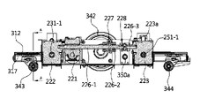
前記第2減速機222は前記第1サブ回転軸226-1の一側端部に連結され、前記第1サブ回転軸226-1の回転を前記第1サブ回転軸226-1と直角をなす前記第1動力伝達部230の第2回転軸231-1、231-2に伝達することになる。
前記第3減速機223は前記第1~第3サブ回転軸226-1、226-2、226-3の他側端部に連結され、前記第1~第3サブ回転軸226-1、226-2、226-3の回転を前記第1~第3サブ回転軸226-1、226-2、226-3と直角をなし、前記第2回転軸231-1、231-2と向かい合う位置に前記第2回転軸231-1、231-2に並んで備えられた第3回転軸251-1、251-2に伝達することになる。
前記第1減速機221と第2減速機222と第3減速機223ではウォームギア方式で連結されて2個の直交する軸の間に回転を伝達することになる。
前記第1動力伝達部230は前記第2回転軸231-1、231-2、カム部材232、233、昇降部材235、236を含むことができる。
前記第2回転軸231-1、231-2の一側端部は前記第2減速機222に連結されており、前記第2回転軸231-1、231-2は長さ方向に沿って複数の部品によって回転可能に支持される。
前記第2回転軸231-1、231-2は、前記第1サブ回転軸226-1と垂直となるように前記第2減速機222に連結された第4サブ回転軸231-1、前記第4サブ回転軸231-1が他側端部に連結された第5サブ回転軸231-2で構成される。
前記第5サブ回転軸231-2は支持ブロック245を貫通し、前記貫通する部分にはベアリングが介在されて前記第5サブ回転軸231-2を回転可能に支持している。
前記第4サブ回転軸231-1は支持ブロック246を貫通し、前記貫通する部分にはベアリングが介在されて前記第4サブ回転軸231-1を回転可能に支持している。
前記第4サブ回転軸231-1と第5サブ回転軸231-2の間は第3カプラ234により連結される。
前記カム部材232、233は前記第5サブ回転軸231-2の端部に連結されたカム部材232と前記第4サブ回転軸231-3の端部に連結されたカム部材233で構成される。前記一側のカム部材232は昇降部材235と一体に昇降可能なように係止され、前記他側のカム部材233は昇降部材236と一体に昇降可能なように係止される。
前記一側のカム部材232はガイドブロック237と一体に結合されており、前記ガイドブロック237は上下方向の長さを有するガイドレール241に上下移動可能なように結合されている。
前記昇降部材235はガイドブロック237と共に上下方向に昇降することになり、前記ガイドレール241はガイドブロック237の昇降時にガイドブロック237の上下移動をガイドすることになる。
前記ガイドレール241は側部プレート315に結合されている。
前記他側のカム部材233はガイドブロック238と一体に結合されており、前記ガイドブロック238は上下方向の長さをガイドレール242に上下移動可能なように結合されている。
前記昇降部材236はガイドブロック238と共に上下方向に昇降することになり、前記ガイドレール242はガイドブロック238の昇降時にガイドブロック238の上下移動をガイドすることになる。
前記ガイドレール242は側部プレート313に結合されている。
前記他側のガイドブロック238とガイドレール242は前記一側のガイドブロック237とガイドレール241に対称となるように備えられている。
前記第2動力伝達部250は前記第3回転軸251-1、251-2、カム部材252、253、昇降部材255、256を含み、前記第1動力伝達部230と対向する位置に並んでいるように備えられ、第1動力伝達部230の構成と同じ構成で構成され得る。
前記第3回転軸251-1、251-2は第6サブ回転軸251-1、第7サブ回転軸251-2で構成され、前記第2回転軸231-1、231-2と同じ構成で対抗する位置に並んで備えられている。
前記第7サブ回転軸251-2は支持ブロック265を貫通し、前記貫通する部分にはベアリングが介在されて前記第7サブ回転軸251-2を回転可能に支持している。
前記第6サブ回転軸251-1は支持ブロック266を貫通し、前記貫通する部分にはベアリングが介在されて前記第6サブ回転軸251-1を回転可能に支持している。
前記第6サブ回転軸251-1と第7サブ回転軸251-2の間は第4カプラ254により連結される。
前記一側のカム部材252と昇降部材255は前記第1動力伝達部230のカム部材232および昇降部材235と同じ構成で形成されている。
前記他側のカム部材253と昇降部材256は前記第1動力伝達部230のカム部材233および昇降部材236と同じ構成で形成され、前記一側のカム部材252と昇降部材255とは対称となるように備えられている。
前記一側の昇降部材255と一体に結合されたガイドブロック257、前記ガイドブロック257の上下移動をガイドするためのガイドレール261が備えられる。前記ガイドブロック257とガイドレール261は第1動力伝達部230のガイドブロック237とガイドレール241と同じ構成で形成されている。
前記他側の昇降部材256と一体に結合されたガイドブロック258、前記ガイドブロック258の上下移動をガイドするためのガイドレール262が備えられる。前記ガイドブロック258とガイドレール262は第1動力伝達部230のガイドブロック238とガイドレール242と同じ構成で形成されている。
The configuration of the
The
The elevating driving means 210 may include an elevating
A
With this configuration, the driving force generated by one lifting
The
The
The first rotating shafts 226-1, 226-2, and 226-3 are first to third gears that transmit the torque transmitted from the
The first sub-rotating shaft 226-1 and the second sub-rotating shaft 226-2 are connected by a
The
The
The
The first
One end of the second rotating shafts 231-1 and 231-2 is connected to the
The second rotating shafts 231-1 and 231-2 are connected to the
The fifth sub-rotating shaft 231-2 passes through the
The fourth sub-rotating shaft 231-1 passes through the
A
The
The
The lifting
The
The
The lifting
The
The
The second
The third rotating shafts 251-1 and 251-2 are composed of a sixth sub-rotating shaft 251-1 and a seventh sub-rotating shaft 251-2, and have the same configuration as the second rotating shafts 231-1 and 231-2. They are provided side by side in opposing positions.
The seventh sub-rotating shaft 251-2 passes through the
The sixth sub-rotating shaft 251-1 passes through the
A
The
The
A
A
図11と図12を参照してカム部材232と昇降部材235について説明する。
前記カム部材232は円板の形状であって、第5サブ回転軸231-2の端部に結合されて第5サブ回転軸231-2と一体に回転することになる。前記カム部材232の側面のうち前記第5サブ回転軸231-2が結合された反対側面には前記第5サブ回転軸231-2の軸方向に突出したカム突出部232aが形成されている。
前記カム突出部232aは前記円板の形状のカム部材232の中心から外側に偏心した位置に形成されている。
前記昇降部材235は直六面体状で形成され、前記カム突出部232aと対向する側面には水平方向の長さで凹んで形成されたガイド溝235aが形成されており、前記カム部材232の回転によって上下方向に直線運動することになる。
前記カム突出部232aは前記ガイド溝235aに挿入されている。前記カム突出部232aが前記カム部材232で上死点にある場合と下死点にある場合には前記カム突出部232aが前記ガイド溝235aの内部で中央に位置することができる。
前記カム突出部232aが下死点にある状態で、前記カム部材232が一例として、時計回り方向に90度回転すると、前記カム突出部232aは前記ガイド溝235aの中央位置から一側縁の位置に移動することになり、前記昇降部材235は前記カム突出部232aと係止状態で力を受けて上昇することになる。
その後、前記カム部材232が時計回り方向に90度さらに回転することになると、前記カム突出部232aは上死点に位置することになり、カム突出部232aは前記ガイド溝235aの一側縁の位置から中央位置に移動することになり、前記昇降部材235はさらに上昇することになる。
その後、前記カム部材232が時計回り方向に90度さらに回転することになると、前記カム突出部232aは前記ガイド溝235aの中央位置から他側縁の位置に移動することになり、前記昇降部材235は自重および前記カム突出部232aと係止状態で力を受けて下降することになる。
The
The
The
The elevating
The
For example, when the
After that, when the
After that, when the
その後、前記カム部材232が時計回り方向に90度さらに回転することになると、カム突出部232aは下死点に位置することになり、カム突出部232aは前記ガイド溝235aの他側縁の位置から中央位置に移動することになり、前記昇降部材235はさらに下降することになる。
したがって、前記カム部材232が360度回転しても前記カム突出部232aは前記ガイド溝235aの内部で水平移動し、前記昇降部材235の昇降が可能となる。
前記他側のカム部材233と昇降部材236は一側のカム部材232および昇降部材235と同じ構成であって、対称となるように備えられている。
前記一側のカム突出部232aは前記他側のカム突出部233aは互いに反対の方向に遠くなる方向に突出しており、前記一側の昇降部材235のガイド溝235aと他側の昇降部材236のガイド溝(図示されず)は互いに向かい合う方向となるように形成されている。
この場合、前記一側のカム部材232のカム突出部232aと他側のカム部材233のカム突出部は第2回転軸231-1、231-2に対して対称となるように同じ角度で形成されている。
すなわち、第2回転軸231-1、231-2の軸方向から見た時、前記一側のカム部材232の位相と他側のカム部材233の位相は同じとなる。したがって、一側のカム部材232と他側のカム部材233は第2回転軸231-1、231-2の回転時に同じ位相でともに回転して積載板110の一側の下部に昇降させる力を同時に作用させることになる。
このように一対のカム部材232、233と一対の昇降部材235、236は第1組立体1の一側と他側にそれぞれ備えられ、積載板110の一側端の両側の下部に上下方向に昇降させる力を作用するように構成されている。
一方、第2組立体2に備えられた一対のカム部材252、253と一対の昇降部材255、256も第1組立体1に備えられた一対のカム部材232、233と一対の昇降部材235、236と同じ構成で形成されているので、詳しい説明は省略する。
After that, when the
Therefore, even if the
The
The
In this case, the
That is, when viewed from the axial direction of the second rotating shafts 231-1 and 231-2, the phase of the
As described above, the pair of
On the other hand, the pair of
図6、図7、図8、図10、図11を参照して第1組立体1に備えられた昇降支持部410、420と第2組立体2に備えられた昇降支持部430、440について説明する。
前記第1組立体1に備えられた一対の昇降支持部410、420は、前記第5サブ回転軸231-2に連結されたカム部材232の回転によって上下に昇降する昇降部材235の上部に結合された第1昇降支持部410、前記第4サブ回転軸231-1に連結されたカム部材233の回転によって上下に昇降する昇降部材236の上部に結合された第2昇降支持部420で構成される。
前記第2組立体2に備えられた一対の昇降支持部410、420は、第7サブ回転軸251-2に連結されたカム部材252の回転によって上下に昇降する昇降部材255の上部に結合された第3昇降支持部430、前記第6サブ回転軸251-1に連結されたカム部材253の回転によって上下に昇降する昇降部材256の上部に結合された第4昇降支持部440で構成される。
前記第1~第4昇降支持部410、420、430、440は前記上部支持プレート120の縁の底面に結合されて、その上部に積載板110および回転駆動部130を支持することになる。
前記第1~第4昇降支持部410、420、430、440は上部構造物との間に捩じれなどによって発生する相対回転を許容するためにボールジョイント構造で形成されている。
この場合、前記第1昇降支持部410と第2昇降支持部420ではボールジョイント構造によって相対回転のみ許容し、前記第3昇降支持部430と第4昇降支持部440ではボールジョイント構造による相対回転と前記第1回転軸226-1、226-2、226-3の軸方向と並んでいる方向にスライド移動を許容できる構造になっている。
前記第1~第4昇降支持部410の基本的な構成は共通している。すなわち、前記第1~第4昇降支持部410、420、430、440は、上部支持プレート120の底面に結合され、垂直断面が「∩」の形状で形成された昇降支持台411、421、431、441、前記昇降支持台411、421、431、441の内部にボール部が備えられたボールジョイント412、422、432、442、両側端部が前記昇降支持台411、421、431、441に結合され、中央部で前記ボールジョイント412、422、432、442のボール部との間に相対回転が行われる連結軸413、423、433、443でそれぞれ構成されている。
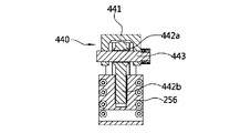
図8と図10を参照する。第3、第4昇降支持部430、440に備えられたボールジョイント432、442は、球状に形成されたボール部432a、442aと前記ボール部432a、442aから下向きに延びた軸部432b、442bで構成されている。前記軸部432b、442bは昇降部材255、256に結合されている。前記連結軸433、443は第1回転軸226-1、226-2と並んでいる方向の長さを有して前記ボール部432a、442aを貫通するようになっているため、前記連結軸433、443に結合された昇降支持台431、441が前記ボール部432a、442aとの間で相対回転が可能である。
この場合、図10に示した通り、第4昇降支持部440の連結軸443はボール部442aとの間に連結軸443の長さ方向に沿って相対移動(スライド直線移動)が可能なように、昇降支持台441と連結軸443およびボール部442aの寸法が決定され得る。図面に図示してはいないが、前記第3昇降支持部440も第4昇降支持部440と同じ構成で構成されて、連結軸433はボールジョイント432のボール部との間に連結軸433の長さ方向に沿って相対移動が可能なように昇降支持台431と連結軸433およびボール部432aの寸法が決定され得る。
一方、第1昇降支持台410の場合には、連結軸413とボールジョイント412のボール部412aの間には相対回転のみが行われ、連結軸413の長さ方向に沿った相対移動は行われないようになっている。また、第2昇降支持台420の場合にも、連結軸423とボールジョイント422のボール部の間に相対回転のみが行われ、連結軸423の長さ方向に沿った相対移動は行われないように構成することができる。この場合、前記第1昇降支持台410の連結軸と前記第2昇降支持台420の連結軸423は第2回転軸231-1.231-2と並んでいる方向の長さを有するように備えられる。
With reference to FIGS. 6, 7, 8, 10 and 11,
A pair of elevating
A pair of elevating
The first to fourth elevating
The first to fourth elevating
In this case, the first elevating
The basic configuration of the first to fourth
Please refer to FIGS. 8 and 10. FIG. The ball joints 432, 442 provided in the third and fourth
In this case, as shown in FIG. 10, the connecting
On the other hand, in the case of the first elevating
図13を参照して第1カプラ227について説明する。
前記第1カプラ227は第1サブ回転軸226-1と第2サブ回転軸226-2の間を連結する。
前記複数のカム部材232、233、252、253のカム突出部の位相はすべてが一致しなければならないが、前記第2減速機222と第3減速機223は精密に加工することが難しく、複数の部品が連結されているため、前記カム部材232、233、252、253のカム突出部の位相が互いに一致しない場合が発生し得る。
前記第1カプラ227は、前記カム部材232、233、252、253のカム突出部の位相を互いに一致させた状態で第1サブ回転軸226-1と第2サブ回転軸226-2を結合できるようになっている。
前記第1カプラ227は第1サブ回転軸226-1側に結合される第1サブカプラ227aと第2サブ回転軸226-2側に結合される第2サブカプラ227bで構成される。
前記第1サブカプラ227aは、前記第1サブ回転軸226-1の外側面に接触し、外側面がくさび状に形成され、第1サブ回転軸226-1が中央を貫通する内側加圧部材227-5、前記内側加圧部材227-5のくさび状の外側面に対応して接触するように内側面がくさび状に形成された外側加圧部材227-3、円板の形状で形成され前記第1サブ回転軸226-1の端部が中央を貫通するカプラハウジング227-7、前記外側加圧部材227-3を貫通して終端部がカプラハウジング227-7にねじ結合される締結部材227-1で構成される。
前記締結部材227-1は頭部は外側加圧部材227-3の一側面に接触し、第1サブ回転軸226-1と並んでいる方向の長さを有し、第1サブ回転軸226-1の縁に沿って複数で備えられ得る。
前記内側加圧部材227-5は前記カプラハウジング227-7に一体に形成され得る。
前記第2サブカプラ227bは、前記第2サブ回転軸226-2の外側面に接触し、外側面がくさび状に形成され、第2サブ回転軸226-2が中央を貫通する内側加圧部材227-6、前記内側加圧部材227-6のくさび状の外側面に対応して接触するように内側面がくさび状に形成された外側加圧部材227-4、円板の形状で形成され前記第2サブ回転軸226-2の端部が中央を貫通するカプラハウジング227-8、前記外側加圧部材227-4を貫通して終端部がカプラハウジング227-8にねじ結合される締結部材227-2で構成される。
前記締結部材227-2は頭部は外側加圧部材227-4の一側面に接触し、第2サブ回転軸226-2と並んでいる方向の長さを有し、第2サブ回転軸226-2の縁に沿って複数で備えられ得る。
前記内側加圧部材227-6は前記カプラハウジング227-8に一体に形成され得る。
前記第1サブカプラ227aと第2サブカプラ227bはカプラ連結部227cを挟んで対称となるように備えられる。前記カプラ連結部227cにより前記第1サブカプラ227aと第2サブカプラ227bが一体に結合されている。
前記第1カプラ227を利用して第1サブ回転軸226-1と第2サブ回転軸226-2を連結するためには、まず、前記第1サブ回転軸226-1には第1減速機221と第2減速機222を含んで第2回転軸231-1、231-2とカム部材232、233がすべて連結されており、前記第2サブ回転軸226-2には第2カプラ228と第3減速機223と第3回転軸251-2、251-2およびカム部材252、253がすべて連結されており、第1サブ回転軸226-1と第2サブ回転軸226-2の間には第1カプラ271の締結部材227-1と締結部材227-2が仮締結された状態で第1カプラ271が連結されており、4個のカム部材232、233、252、253のカム突出部の位相をすべて一致させた状態で、前記締結部材227-1、227-2を完全締結することになると、両側の外側加圧部材227-3、227-4が第1サブ回転軸226-1と第2サブ回転軸226-2の向かい合う方向に移動することになり、外側加圧部材227-3、227-4のくさび状の内側面が内側加圧部材227-5、227-6のくさび状の外側傾斜面を伝って上りながら内側加圧部材227-5、227-6が第1サブ回転軸226-1と第2サブ回転軸226-2の半径方向に加圧されて、第1サブ回転軸226-1と第2サブ回転軸226-2に堅固に結合される。
このような構成によると、複数のカム部材232、233、252、253のカム突出部の位相を正確に一致させることができ、これにより、第1組立体1による積載板110の昇降位置と前記第2組立体2による積載板110の昇降位置を一致させることができる。
The
The
The phases of the cam protrusions of the plurality of
The
The
The first sub-coupler 227a contacts the outer surface of the first sub-rotating shaft 226-1, has a wedge-shaped outer surface, and has an inner
The fastening member 227-1 has a head portion contacting one side of the outer pressing member 227-3 and has a length in a direction parallel to the first sub-rotating shaft 226-1. Multiples may be provided along the -1 edge.
The inner pressure member 227-5 may be integrally formed with the coupler housing 227-7.
The second sub-coupler 227b is in contact with the outer surface of the second sub-rotating shaft 226-2, has a wedge-shaped outer surface, and has an inner
The fastening member 227-2 has a head portion contacting one side of the outer pressing member 227-4 and has a length in a direction parallel to the second sub-rotating shaft 226-2. A plurality may be provided along the -2 edge.
The inner pressure member 227-6 may be integrally formed with the coupler housing 227-8.
The first sub-coupler 227a and the second sub-coupler 227b are arranged symmetrically with respect to the
In order to connect the first sub-rotating shaft 226-1 and the second sub-rotating shaft 226-2 using the
With such a configuration, the phases of the cam protrusions of the plurality of
図14を参照して第2カプラ228について説明する。
前記第2サブ回転軸226-2と第3サブ回転軸226-3の間は第2カプラ228により連結される。
前記第2カプラ228は、前記第2サブ回転軸226-2と第3サブ回転軸226-3にそれぞれ結合されている一対のカプラ部材228-1、228-2、前記一対のカプラ部材228-1、228-2の間を連結する複数の連結ピン228-3、228-4で構成されている。
前記一側のカプラ部材228-1には他側のカプラ部材228-2に向かって突出するように対向する位置に一対のカプラ突出本体228-1aが形成されており、前記他側のカプラ部材228-2には一側のカプラ部材228-1に向かって突出するように対向する位置に一対のカプラ突出本体228-2aが形成されている。
前記一側の一対のカプラ突出本体228-1aと他側の一対のカプラ突出本体228-2aは円周方向の周りに沿って交互に形成されているため、突出部が溝に差し込まれる形状で備えられる。
前記一側の連結ピン228-3は前記一対のカプラ突出本体228-1aに結合されるように一対が備えられ、前記他側の連結ピン228-4は前記一対のカプラ突出本体228-2aに結合されるように一対が備えられる。前記一側に備えられた一対の連結ピン228-3は対向する位置に一直線上に備えられ、前記他側に備えられた一対の連結ピン228-4は対向する位置に一直線上に備えられる。また、前記一側に備えられた一対の連結ピン228-3と他側に備えられた一対の連結ピン228-4は第2回転軸226-2、226-3に垂直な平面上で直角となるように備えられる。
前記一対の連結ピン228-3を中心として一側のカプラ部材228-1と他側のカプラ部材228-2が相対回転または捩じれが可能となり、前記一対の連結ピン228-4を中心として一側のカプラ部材228-1と他側のカプラ部材228-2が相対回転または捩じれが可能となる。
したがって、前記第2カプラ228により前記一対の回転軸226-2、226-3の間には前記一対の回転軸226-2、226-3が軸方向に対して捩じれる偏角を吸収する一方、前記一対の回転軸226-2、226-3が軸方向に対して垂直な側方向に偏心することを吸収することができる。
本発明の場合、第1組立体1と第2組立体2がヒンジ部3により連結されており、地面の高さの差によって第1組立体1と第2組立体2の間に相対回転が発生して、第1組立体1に備えられた昇降駆動部200の一部の部品と第2組立体2に備えられた昇降駆動部200の残りの部品が連結される部分で偏心と偏角が発生し得る。この場合、第2カプラ228で偏心と偏角を吸収できるため、偏心と偏角により動力が伝達される部品に発生する衝撃を最小化することができる。
The
A
The
A pair of coupler protruding bodies 228-1a are formed at opposing positions so as to protrude from the one side coupler member 228-1 toward the other side coupler member 228-2. A pair of coupler protruding bodies 228-2a are formed at opposing positions so as to protrude toward the coupler member 228-1 on one side of 228-2.
Since the pair of coupler projecting bodies 228-1a on one side and the pair of coupler projecting bodies 228-2a on the other side are alternately formed along the circumferential direction, the projections are shaped to be inserted into the grooves. Be prepared.
The one side connection pin 228-3 is provided as a pair to be connected to the pair of coupler protrusion bodies 228-1a, and the other side connection pin 228-4 is provided to the pair of coupler protrusion bodies 228-2a. A pair is provided to be coupled. A pair of connecting pins 228-3 provided on the one side are provided on a straight line at opposing positions, and a pair of connecting pins 228-4 on the other side are provided on a straight line at opposing positions. Also, the pair of connecting pins 228-3 provided on one side and the pair of connecting pins 228-4 provided on the other side are perpendicular to the second rotating shafts 226-2 and 226-3. prepared to be.
The coupler member 228-1 on one side and the coupler member 228-2 on the other side can be rotated or twisted relative to each other about the pair of connecting pins 228-3. The coupler member 228-1 on one side and the coupler member 228-2 on the other side can rotate or twist relative to each other.
Therefore, the
In the case of the present invention, the first assembly 1 and the second assembly 2 are connected by the
図6を参照して第3サブ回転軸226-3と第3減速機223の連結構造について説明する。
前記第3サブ回転軸226-3は第3減速機223が連結される部分は第1組立体1に備えられた昇降駆動部200と第2組立体2に備えられた昇降駆動部200の部品が連結される部分である。この部分には地面の高さの差によるヒンジ部3での相対回転が発生する時に第3サブ回転軸226-3と第3減速機223の間に変位が発生し得る。
このような変位を吸収するために、第3サブ回転軸226-3の端部は第3減速機223の内部から軸方向にスライド移動可能なように備えられている。すなわち、第3減速機223の内部には第3サブ回転軸226-3の軸方向に沿って凹んで形成されたスライド溝223aが形成されており、前記第3サブ回転軸226-3は前記スライド溝223aに挿入されている。
前記スライド溝223aの内部に第3サブ回転軸226-3を挿入すると、キーとキー溝の構造によって第3サブ回転軸226-3の回転力がスライド溝223aを通じて伝達されるように第3減速機223に伝達される。これとともに前記スライド溝223aの長さ方向に沿って第3サブ回転軸226-3がスライド移動可能なようになっている。これによって第3サブ回転軸226-3と第3減速機223の間に発生した変位を吸収することができる。
A connection structure between the third sub-rotating shaft 226-3 and the
The portion of the third sub-rotating shaft 226-3 to which the
In order to absorb such displacement, the end of the third sub-rotating shaft 226-3 is provided so as to be axially slidable from inside the
When the third sub-rotating shaft 226-3 is inserted into the
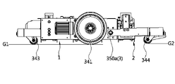
図17を参照する。前方の従動輪343と駆動輪341が接する地面G1よりも後方の従動輪344が接する地面G2がさらに高くなっている。したがって、第1組立体1と第2組立体2はヒンジ部3を中心軸として相対回転が行われる。このような状態ではすべての車輪341、342、343、344が地面に接していることになるので、駆動力が確実に伝達され得る。
See FIG. The ground G2 with which the rear driven
図15と図16を参照する。前方の第1従動輪支持プレート312の下部には左右に離隔した一対の第1従動輪343a、343bが備えられており、後方の第2従動輪支持プレート322の下部には左右に離隔した一対の第2従動輪344a、344bが備えられている。
前記第1従動輪支持プレート312には前後方向の長さを有する棒状の従動輪中心軸345が結合されている。
前記従動輪中心軸345には少なくとも一部が平板の形状である従動輪支持プレート317が、前記従動輪中心軸345を回転中心として左右方向に回動可能なように結合されている。この場合、前記従動輪中心軸345はヒンジ軸3と垂直な方向の長さを有する。
前記従動輪支持プレート317の底面には前記一対の第1従動輪343a、343bが左右に離隔して結合されている。
前記一対の第1従動輪343a、343bのうち、一側の従動輪343aが接する地面と他側の従動輪343bが接する地面のうちいずれかが高い場合、前記従動輪支持プレート317は従動輪中心軸345を回転中心として回動することになる。したがって、一対の第1従動輪343a、343bはすべて地面に接触することになる。
前記第2従動輪支持プレート322には前後方向の長さを有する棒状の従動輪中心軸346が結合されている。
前記従動輪中心軸346には少なくとも一部が平板の形状である従動輪支持プレート318が、前記従動輪中心軸346を回転中心として左右方向に回動可能なように結合されている。この場合、前記従動輪中心軸346はヒンジ軸3と垂直な方向の長さを有する。
前記従動輪支持プレート318の底面には前記一対の第2従動輪344a、344bが左右に離隔して結合されている。
前記一対の第2従動輪344a、344bのうち、一側の従動輪344aが接する地面と他側の従動輪344bが接する地面のうちいずれかが高い場合、前記従動輪支持プレート318は従動輪中心軸346を回転中心として回動することになる。したがって、一対の第2従動輪344a、344bはすべて地面に接触することになる。
前記のような積載物運搬装置によると、積載物を運搬するための運搬装置において、地面が均一でない場合にも駆動輪が常に地面に接触することができ、一つの昇降駆動手段を利用して積載物を安定的に昇降させることができ、積載物運搬装置の高さを低くすることができる。
前述した通り、本発明について好ましい実施例を挙げて詳細に説明したが、本発明は前述した実施例に限定されるものではなく、特許請求の範囲と発明の詳細な説明および添付した図面の範囲内で多様に変形して実施することが可能であり、これもまた本発明に属する。
See FIGS. 15 and 16. FIG. A pair of first driven
A rod-shaped driven
A driven
The pair of first driven
If either the ground surface with which one driven
A rod-shaped driven
A driven
The pair of second driven
If the ground surface with which one driven
According to the load transporting apparatus as described above, in the transporting apparatus for transporting the load, the driving wheels can always contact the ground even if the ground is uneven. The load can be stably raised and lowered, and the height of the load transport device can be reduced.
As noted above, the present invention has been described in detail with reference to preferred embodiments. Various modifications can be made within the scope of the present invention, which also belong to the present invention.
1 第1組立体
2 第2組立体
3a、3b ヒンジ部
110 積載板
200 昇降駆動部
210 昇降駆動手段
220 減速部
221 第1減速機
222 第2減速機
223 第3減速機
223a スライド溝
226-1、226-2、226-3 第1回転軸
227 第1カプラ
227-1、227-2 締結部材
227-3、227-4 外側加圧部材
227-5、227-6 内側加圧部材
227-7、227-8 カプラハウジング
228 第2カプラ
228-1、228-2 カプラ部材
228-3、228-4 連結ピン
230 第1動力伝達部
231-1、231-2 第2回転軸
232、233、252、253 カム部材
232a、233a カム突出部
234 第3カプラ
235、236、255、256 昇降部材
241、242、261、262 ガイドレール
250 第2動力伝達部
251-1、251-2 第3回転軸
254 第4カプラ
245、246、265、266 支持ブロック
311 第1底プレート
312 第1従動輪支持プレート
313、314、315、316 側部プレート
317、318 従動輪支持プレート
321 第2底プレート
322 第2従動輪支持プレート
323、324 側部ハウジング
341、342 駆動輪
343a、343b 第1従動輪
344a、344b 第2従動輪
345、346 従動輪中心軸
410、420、430、440 昇降支持部
411、421、431、441 昇降支持台
412、422、432、442 ボールジョイント
413、423、433、443 連結軸
1 First assembly 2 Second assembly 3a, 3b Hinge part 110 Loading plate 200 Elevation drive part 210 Elevation drive means 220 Reduction part 221 First reduction gear 222 Second reduction gear 223 Third reduction gear 223a Slide groove 226-1 , 226-2, 226-3 First rotating shaft 227 First coupler 227-1, 227-2 Fastening member 227-3, 227-4 Outer pressure member 227-5, 227-6 Inner pressure member 227-7 , 227-8 Coupler housing 228 Second coupler 228-1, 228-2 Coupler member 228-3, 228-4 Connecting pin 230 First power transmission part 231-1, 231-2 Second rotating shaft 232, 233, 252 , 253 Cam members 232a, 233a Cam protrusion 234 Third coupler 235, 236, 255, 256 Elevating member 241, 242, 261, 262 Guide rail 250 Second power transmission section 251-1, 251-2 Third rotating shaft 254 fourth coupler 245, 246, 265, 266 support block 311 first bottom plate 312 first driven wheel support plate 313, 314, 315, 316 side plate 317, 318 driven wheel support plate 321 second bottom plate 322 second Drive wheel support plates 323, 324 Side housings 341, 342 Drive wheels 343a, 343b First driven wheels 344a, 344b Second driven wheels 345, 346 Driven wheel center shafts 410, 420, 430, 440 Lifting support parts 411, 421, 431 , 441 lifting support base 412, 422, 432, 442 ball joint 413, 423, 433, 443 connecting shaft
Claims (12)
前記積載板を上下に昇降させるための駆動力を発生させる昇降駆動部(200)、
前記積載板の一側の下部を支持し、前記昇降駆動部(200)を構成する部品の一部が備えられた第1組立体(1)、
前記積載板の他側の下部を支持し、前記昇降駆動部(200)を構成する部品の残りが備えられた第2組立体(2)、
前記第1組立体(1)と第2組立体(2)をヒンジ構造で連結するヒンジ部(3a、3b)、
前記第1組立体(1)または第2組立体(2)のうちいずれか一つの下部の両側に結合された少なくとも一対の駆動輪(341、342)、
前記駆動輪(341、342)を回転駆動させる駆動手段、を含み、
前記昇降駆動部は、前記積載板を上下に昇降させるための回転力を発生させる昇降駆動手段(210)を含み、前記第1組立体(1)には前記昇降駆動手段(210)の回転力を前記第2組立体(2)に備えられた昇降駆動部(200)を構成する部品に伝達するための少なくとも一対の回転軸(226-1、226-2)が備えられ、前記一対の回転軸(226-1、226-2)の間には前記第1組立体(1)による前記積載板の昇降位置と前記第2組立体(2)による前記積載板の昇降位置を一致させた後、前記一対の回転軸(226-1、226-2)を結合するための第1カプラ(227)が連結されたことを特徴とする、
積載物運搬装置。 a loading plate (110) on which a load is loaded;
a lifting drive unit (200) for generating driving force for lifting and lowering the stacking plate;
a first assembly (1) that supports a lower portion of one side of the loading plate and includes a part of the parts that constitute the elevation driving part (200);
a second assembly (2) that supports the lower part of the other side of the loading plate and includes the rest of the parts that constitute the lifting drive part (200);
Hinge parts (3a, 3b) connecting the first assembly (1) and the second assembly (2) with a hinge structure;
at least a pair of drive wheels (341, 342) coupled to both sides of a lower portion of either the first assembly (1) or the second assembly (2);
driving means for rotationally driving the driving wheels (341, 342) ,
The elevation driving unit includes an elevation driving means (210) for generating a rotational force for vertically raising and lowering the loading plate, and the rotational force of the elevation driving means (210) is applied to the first assembly (1) at least a pair of rotating shafts (226-1, 226-2) for transmitting to the parts constituting the lifting drive unit (200) provided in the second assembly (2), and the pair of rotating shafts (226-1, 226-2) After matching the elevation position of the loading plate by the first assembly (1) with the elevation position of the loading plate by the second assembly (2) between the shafts (226-1, 226-2) , characterized in that a first coupler (227) for coupling the pair of rotating shafts (226-1, 226-2) is connected,
Load carrier.
前記積載板を上下に昇降させるための駆動力を発生させる昇降駆動部(200)、
前記積載板の一側の下部を支持し、前記昇降駆動部(200)を構成する部品の一部が備えられた第1組立体(1)、
前記積載板の他側の下部を支持し、前記昇降駆動部(200)を構成する部品の残りが備えられた第2組立体(2)、
前記第1組立体(1)と第2組立体(2)をヒンジ構造で連結するヒンジ部(3a、3b)、
前記第1組立体(1)または第2組立体(2)のうちいずれか一つの下部の両側に結合された少なくとも一対の駆動輪(341、342)、
前記駆動輪(341、342)を回転駆動させる駆動手段、を含み、
前記昇降駆動部は、前記積載板を上下に昇降させるための回転力を発生させる昇降駆動手段(210)を含み、前記第1組立体(1)には前記昇降駆動手段(210)の回転力を前記第2組立体(2)に備えられた昇降駆動部(200)を構成する部品に伝達するための少なくとも一対の回転軸(226-2、226-3)が備えられ、前記一対の回転軸(226-2、226-3)の間には前記一対の回転軸(226-2、226-3)が軸方向に対して捩じれる偏角を吸収する一方、前記一対の回転軸(226-2、226-3)が軸方向に対して垂直な側方向に偏心することを吸収できる第2カプラ(228)が連結されたことを特徴とする、
積載物運搬装置。 a loading plate (110) on which a load is loaded;
a lifting drive unit (200) for generating driving force for lifting and lowering the stacking plate;
a first assembly (1) that supports a lower portion of one side of the loading plate and includes a part of the parts that constitute the elevation driving part (200);
a second assembly (2) that supports the lower part of the other side of the loading plate and includes the rest of the parts that constitute the lifting drive part (200);
Hinge parts (3a, 3b) connecting the first assembly (1) and the second assembly (2) with a hinge structure;
at least a pair of drive wheels (341, 342) coupled to both sides of a lower portion of either the first assembly (1) or the second assembly (2);
driving means for rotationally driving the driving wheels (341, 342),
The elevation driving unit includes an elevation driving means (210) for generating a rotational force for vertically raising and lowering the loading plate, and the rotational force of the elevation driving means (210) is applied to the first assembly (1) at least a pair of rotating shafts (226-2, 226-3) for transmitting to the parts constituting the lifting drive unit (200) provided in the second assembly (2), and the pair of rotating shafts (226-2, 226-3) Between the shafts (226-2, 226-3), the pair of rotating shafts (226-2, 226-3) absorbs the twisting angle with respect to the axial direction, while the pair of rotating shafts (226-2, 226-3) -2, 226-3) is coupled with a second coupler (228) capable of absorbing lateral eccentricity perpendicular to the axial direction ,
Load carrier.
前記第1組立体(1)の底面に結合された一対の第1従動輪(343a、343b)、前記第2組立体(2)の底面に結合された一対の第2従動輪(344a、344b)、前記一対の第1従動輪(343a、343b)を構成する一側の従動輪(343a)と他側の従動輪(343b)は前記ヒンジ軸(350a、350b)と垂直な方向の長さを有する従動輪中心軸(345)を中心に回動可能であり、前記一対の第2従動輪(344a、344b)を構成する一側の従動輪(344a)と他側の従動輪(344b)は前記ヒンジ軸(350a、350b)と垂直な方向の長さを有する従動輪中心軸(346)を中心に回動可能となることを特徴とする、請求項1に記載の積載物運搬装置。 Said hinge portions (3a, 3b) provide a hinged connection between adjacent ends of said first assembly (1) and said second assembly (2), thereby and the second assembly (2) are relatively rotatable around a pair of hinge shafts (350a, 350b) having a length in the left-right direction perpendicular to the running direction,
A pair of first driven wheels (343a, 343b) coupled to the bottom surface of the first assembly (1), and a pair of second driven wheels (344a, 344b) coupled to the bottom surface of the second assembly (2). ), the length of the driven wheel (343a) on one side and the driven wheel (343b) on the other side constituting the pair of first driven wheels (343a, 343b) in the direction perpendicular to the hinge shafts (350a, 350b) and a driven wheel (344a) on one side and a driven wheel (344b) on the other side that constitute the pair of second driven wheels (344a, 344b). 2. The load carrying device according to claim 1, wherein is rotatable about a driven wheel central axis (346) having a length in a direction perpendicular to said hinge axis (350a, 350b).
Applications Claiming Priority (3)
| Application Number | Priority Date | Filing Date | Title |
|---|---|---|---|
| KR10-2020-0058056 | 2020-05-15 | ||
| KR1020200058056A KR102212917B1 (en) | 2020-05-15 | 2020-05-15 | Carrying apparatus of loading article |
| PCT/KR2020/009652 WO2021230423A1 (en) | 2020-05-15 | 2020-07-22 | Load transporting apparatus |
Publications (2)
| Publication Number | Publication Date |
|---|---|
| JP2022536562A JP2022536562A (en) | 2022-08-18 |
| JP7204237B2 true JP7204237B2 (en) | 2023-01-16 |
Family
ID=74558962
Family Applications (1)
| Application Number | Title | Priority Date | Filing Date |
|---|---|---|---|
| JP2020553530A Active JP7204237B2 (en) | 2020-05-15 | 2020-07-22 | Load carrier |
Country Status (4)
| Country | Link |
|---|---|
| US (1) | US11904461B2 (en) |
| JP (1) | JP7204237B2 (en) |
| KR (1) | KR102212917B1 (en) |
| WO (1) | WO2021230423A1 (en) |
Families Citing this family (10)
| Publication number | Priority date | Publication date | Assignee | Title |
|---|---|---|---|---|
| US11845372B2 (en) * | 2018-09-07 | 2023-12-19 | Murata Machinery, Ltd. | Transport vehicle |
| KR102644842B1 (en) * | 2022-02-10 | 2024-03-08 | 성균관대학교산학협력단 | Driving device for robot |
| JP7349110B1 (en) | 2022-11-25 | 2023-09-22 | 株式会社匠 | automated guided vehicle |
| KR102870249B1 (en) * | 2023-01-30 | 2025-10-14 | 주식회사 모션디바이스 | Automatic guided vehicle |
| KR102951863B1 (en) * | 2023-06-28 | 2026-04-13 | 한양이엔지 주식회사 | Multi Coupler Connection Device |
| WO2025178231A1 (en) * | 2024-02-20 | 2025-08-28 | 주식회사 모션디바이스 | Unmanned transport vehicle |
| US12416930B1 (en) | 2024-03-01 | 2025-09-16 | Robust AI, Inc. | Systems and methods for an autonomous mobile robot |
| US12436546B2 (en) | 2024-03-01 | 2025-10-07 | Robust AI, Inc. | Systems and methods for an autonomous mobile robot fleet coordination |
| US12204350B1 (en) * | 2024-03-04 | 2025-01-21 | Robust AI, Inc. | Autonomous robot double drive assembly |
| JP7823704B1 (en) * | 2024-09-17 | 2026-03-04 | 株式会社明電舎 | automated guided vehicle |
Citations (4)
| Publication number | Priority date | Publication date | Assignee | Title |
|---|---|---|---|---|
| CN105730553A (en) | 2016-02-05 | 2016-07-06 | 广东嘉腾机器人自动化有限公司 | AGV chassis structure capable of adapting to ground deformation |
| CN207015475U (en) | 2017-08-09 | 2018-02-16 | 杭州海康机器人技术有限公司 | A kind of automatical pilot transportation vehicle |
| JP2018520967A (en) | 2015-06-25 | 2018-08-02 | アマゾン テクノロジーズ インコーポレイテッド | Tilt platform for stability control |
| JP2020023291A (en) | 2018-08-08 | 2020-02-13 | シャープ株式会社 | Transport dolly |
Family Cites Families (16)
| Publication number | Priority date | Publication date | Assignee | Title |
|---|---|---|---|---|
| JP2753791B2 (en) * | 1993-05-21 | 1998-05-20 | 本田技研工業株式会社 | How to assemble a motorcycle |
| US6390213B1 (en) * | 1998-11-16 | 2002-05-21 | Joel N. Bleicher | Maneuverable self-propelled cart |
| KR20090102888A (en) * | 2008-03-27 | 2009-10-01 | 에스엠에이치 주식회사 | Traverser |
| KR101247765B1 (en) * | 2011-02-23 | 2013-03-25 | 삼성중공업 주식회사 | Moving device |
| NO2966067T3 (en) * | 2013-08-12 | 2018-03-24 | ||
| DE102013016118A1 (en) * | 2013-09-26 | 2015-03-26 | Grenzebach Maschinenbau Gmbh | Transport vehicle and method for trouble-free transport of load racks in factory halls with partially autonomous driving |
| DE102013016381A1 (en) * | 2013-09-30 | 2015-04-02 | Grenzebach Maschinenbau Gmbh | Transport vehicle and method for the trouble-free transport of load racks in factory halls with radio shading and with partially autonomous driving operation |
| DE102014000375A1 (en) * | 2014-01-14 | 2015-07-16 | Grenzebach Maschinenbau Gmbh | Device for orientation for automatically in factory halls run, electrically operated, transport vehicles |
| US20160340162A1 (en) * | 2014-04-01 | 2016-11-24 | The Raymond Corporation | Caster wheels with torsion spring assembly |
| KR101642728B1 (en) | 2015-03-02 | 2016-07-27 | 씨제이대한통운 (주) | Logistics transport system |
| KR101734708B1 (en) * | 2015-11-23 | 2017-05-11 | 기아자동차주식회사 | Automated Guided Vehicle |
| KR101772631B1 (en) | 2015-12-11 | 2017-09-13 | 주식회사 마로로봇 테크 | Logistics robot position correction driving device |
| KR102500301B1 (en) * | 2016-07-13 | 2023-02-16 | 주식회사 노바 | Fuel cell module driven type products tranferring robot |
| KR101987777B1 (en) * | 2017-09-21 | 2019-06-13 | (주)씨에이시스템 | Frame Curve Type Automated Guided Vehicle Removable Battery using a Sliding Method |
| US11845372B2 (en) * | 2018-09-07 | 2023-12-19 | Murata Machinery, Ltd. | Transport vehicle |
| KR102208994B1 (en) * | 2019-11-11 | 2021-01-28 | 주식회사 모션디바이스 | Driving apparatus maintaining ground contact of drive-wheel |
-
2020
- 2020-05-15 KR KR1020200058056A patent/KR102212917B1/en active Active
- 2020-07-22 WO PCT/KR2020/009652 patent/WO2021230423A1/en not_active Ceased
- 2020-07-22 JP JP2020553530A patent/JP7204237B2/en active Active
- 2020-07-22 US US17/043,631 patent/US11904461B2/en active Active
Patent Citations (4)
| Publication number | Priority date | Publication date | Assignee | Title |
|---|---|---|---|---|
| JP2018520967A (en) | 2015-06-25 | 2018-08-02 | アマゾン テクノロジーズ インコーポレイテッド | Tilt platform for stability control |
| CN105730553A (en) | 2016-02-05 | 2016-07-06 | 广东嘉腾机器人自动化有限公司 | AGV chassis structure capable of adapting to ground deformation |
| CN207015475U (en) | 2017-08-09 | 2018-02-16 | 杭州海康机器人技术有限公司 | A kind of automatical pilot transportation vehicle |
| JP2020023291A (en) | 2018-08-08 | 2020-02-13 | シャープ株式会社 | Transport dolly |
Also Published As
| Publication number | Publication date |
|---|---|
| WO2021230423A1 (en) | 2021-11-18 |
| KR102212917B1 (en) | 2021-02-05 |
| US20230191589A1 (en) | 2023-06-22 |
| JP2022536562A (en) | 2022-08-18 |
| US11904461B2 (en) | 2024-02-20 |
Similar Documents
| Publication | Publication Date | Title |
|---|---|---|
| JP7204237B2 (en) | Load carrier | |
| JP7349110B1 (en) | automated guided vehicle | |
| JP6801015B2 (en) | Guide module and drive unit equipped with it | |
| US20230101404A1 (en) | Payload lifting device | |
| KR102206311B1 (en) | Lifting device for agv | |
| JP2021510138A (en) | Displacement mechanism for remote controlled vehicles | |
| CN105731295A (en) | Rotatable submerged automated guided vehicle with independent jacking structure | |
| KR101835199B1 (en) | Robot for transferring substrate | |
| EP1832445B1 (en) | Universal transmission roller wheel | |
| US11858567B2 (en) | Movable object | |
| CN112958933B (en) | Auto body welding production line | |
| CN101148044A (en) | SCARA arm | |
| KR200496746Y1 (en) | Guide driving structure of tool magazine of machine tools | |
| CN102312968B (en) | Flexible transmission column device | |
| JP7137871B2 (en) | A running gear that maintains contact of the drive wheels with the ground | |
| KR102314364B1 (en) | Robot for transferring substrate | |
| KR102223089B1 (en) | Power Transmission Device for Gantry Crane and Gantry Crane Apparatus Therewith | |
| CN217101801U (en) | Lifting conveyor | |
| WO2021097806A1 (en) | Conveyor, conveying system and manufacturing method of conveyor | |
| WO2020119388A1 (en) | Inelastic suspension frame structure for automatically guiding vehicle | |
| CN112209009B (en) | Stacking access system and method | |
| CN212798179U (en) | Multifunctional conveying shuttle | |
| JP6291244B2 (en) | Transport cart | |
| RU2291811C2 (en) | Chassis of mobile transport equipment | |
| JPH0647854Y2 (en) | Carrier |
Legal Events
| Date | Code | Title | Description |
|---|---|---|---|
| A621 | Written request for application examination |
Free format text: JAPANESE INTERMEDIATE CODE: A621 Effective date: 20201001 |
|
| A131 | Notification of reasons for refusal |
Free format text: JAPANESE INTERMEDIATE CODE: A131 Effective date: 20220823 |
|
| A521 | Request for written amendment filed |
Free format text: JAPANESE INTERMEDIATE CODE: A523 Effective date: 20221020 |
|
| TRDD | Decision of grant or rejection written | ||
| A01 | Written decision to grant a patent or to grant a registration (utility model) |
Free format text: JAPANESE INTERMEDIATE CODE: A01 Effective date: 20221206 |
|
| A61 | First payment of annual fees (during grant procedure) |
Free format text: JAPANESE INTERMEDIATE CODE: A61 Effective date: 20221221 |
|
| R150 | Certificate of patent or registration of utility model |
Ref document number: 7204237 Country of ref document: JP Free format text: JAPANESE INTERMEDIATE CODE: R150 |
|
| R250 | Receipt of annual fees |
Free format text: JAPANESE INTERMEDIATE CODE: R250 |