JP7205706B2 - LAMINATED BODY MANUFACTURING APPARATUS AND LAMINATED PRODUCTION METHOD - Google Patents
LAMINATED BODY MANUFACTURING APPARATUS AND LAMINATED PRODUCTION METHOD Download PDFInfo
- Publication number
- JP7205706B2 JP7205706B2 JP2021550328A JP2021550328A JP7205706B2 JP 7205706 B2 JP7205706 B2 JP 7205706B2 JP 2021550328 A JP2021550328 A JP 2021550328A JP 2021550328 A JP2021550328 A JP 2021550328A JP 7205706 B2 JP7205706 B2 JP 7205706B2
- Authority
- JP
- Japan
- Prior art keywords
- polymer film
- heat
- laminate
- resistant polymer
- coupling agent
- Prior art date
- Legal status (The legal status is an assumption and is not a legal conclusion. Google has not performed a legal analysis and makes no representation as to the accuracy of the status listed.)
- Active
Links
Images


Classifications
-
- H—ELECTRICITY
- H10—SEMICONDUCTOR DEVICES; ELECTRIC SOLID-STATE DEVICES NOT OTHERWISE PROVIDED FOR
- H10P—GENERIC PROCESSES OR APPARATUS FOR THE MANUFACTURE OR TREATMENT OF DEVICES COVERED BY CLASS H10
- H10P14/00—Formation of materials, e.g. in the shape of layers or pillars
- H10P14/60—Formation of materials, e.g. in the shape of layers or pillars of insulating materials
- H10P14/68—Organic materials, e.g. photoresists
- H10P14/683—Organic materials, e.g. photoresists carbon-based polymeric organic materials, e.g. polyimides, poly cyclobutene or PVC
-
- B—PERFORMING OPERATIONS; TRANSPORTING
- B29—WORKING OF PLASTICS; WORKING OF SUBSTANCES IN A PLASTIC STATE IN GENERAL
- B29C—SHAPING OR JOINING OF PLASTICS; SHAPING OF MATERIAL IN A PLASTIC STATE, NOT OTHERWISE PROVIDED FOR; AFTER-TREATMENT OF THE SHAPED PRODUCTS, e.g. REPAIRING
- B29C63/00—Lining or sheathing, i.e. applying preformed layers or sheathings of plastics; Apparatus therefor
- B29C63/02—Lining or sheathing, i.e. applying preformed layers or sheathings of plastics; Apparatus therefor using sheet or web-like material
- B29C63/024—Lining or sheathing, i.e. applying preformed layers or sheathings of plastics; Apparatus therefor using sheet or web-like material the sheet or web-like material being supported by a moving carriage
-
- B—PERFORMING OPERATIONS; TRANSPORTING
- B32—LAYERED PRODUCTS
- B32B—LAYERED PRODUCTS, i.e. PRODUCTS BUILT-UP OF STRATA OF FLAT OR NON-FLAT, e.g. CELLULAR OR HONEYCOMB, FORM
- B32B37/00—Methods or apparatus for laminating, e.g. by curing or by ultrasonic bonding
- B32B37/10—Methods or apparatus for laminating, e.g. by curing or by ultrasonic bonding characterised by the pressing technique, e.g. using action of vacuum or fluid pressure
-
- B—PERFORMING OPERATIONS; TRANSPORTING
- B29—WORKING OF PLASTICS; WORKING OF SUBSTANCES IN A PLASTIC STATE IN GENERAL
- B29C—SHAPING OR JOINING OF PLASTICS; SHAPING OF MATERIAL IN A PLASTIC STATE, NOT OTHERWISE PROVIDED FOR; AFTER-TREATMENT OF THE SHAPED PRODUCTS, e.g. REPAIRING
- B29C63/00—Lining or sheathing, i.e. applying preformed layers or sheathings of plastics; Apparatus therefor
- B29C63/02—Lining or sheathing, i.e. applying preformed layers or sheathings of plastics; Apparatus therefor using sheet or web-like material
-
- B—PERFORMING OPERATIONS; TRANSPORTING
- B29—WORKING OF PLASTICS; WORKING OF SUBSTANCES IN A PLASTIC STATE IN GENERAL
- B29C—SHAPING OR JOINING OF PLASTICS; SHAPING OF MATERIAL IN A PLASTIC STATE, NOT OTHERWISE PROVIDED FOR; AFTER-TREATMENT OF THE SHAPED PRODUCTS, e.g. REPAIRING
- B29C65/00—Joining or sealing of preformed parts, e.g. welding of plastics materials; Apparatus therefor
- B29C65/02—Joining or sealing of preformed parts, e.g. welding of plastics materials; Apparatus therefor by heating, with or without pressure
-
- B—PERFORMING OPERATIONS; TRANSPORTING
- B29—WORKING OF PLASTICS; WORKING OF SUBSTANCES IN A PLASTIC STATE IN GENERAL
- B29C—SHAPING OR JOINING OF PLASTICS; SHAPING OF MATERIAL IN A PLASTIC STATE, NOT OTHERWISE PROVIDED FOR; AFTER-TREATMENT OF THE SHAPED PRODUCTS, e.g. REPAIRING
- B29C65/00—Joining or sealing of preformed parts, e.g. welding of plastics materials; Apparatus therefor
- B29C65/48—Joining or sealing of preformed parts, e.g. welding of plastics materials; Apparatus therefor using adhesives, i.e. using supplementary joining material; solvent bonding
-
- B—PERFORMING OPERATIONS; TRANSPORTING
- B29—WORKING OF PLASTICS; WORKING OF SUBSTANCES IN A PLASTIC STATE IN GENERAL
- B29C—SHAPING OR JOINING OF PLASTICS; SHAPING OF MATERIAL IN A PLASTIC STATE, NOT OTHERWISE PROVIDED FOR; AFTER-TREATMENT OF THE SHAPED PRODUCTS, e.g. REPAIRING
- B29C65/00—Joining or sealing of preformed parts, e.g. welding of plastics materials; Apparatus therefor
- B29C65/48—Joining or sealing of preformed parts, e.g. welding of plastics materials; Apparatus therefor using adhesives, i.e. using supplementary joining material; solvent bonding
- B29C65/4805—Joining or sealing of preformed parts, e.g. welding of plastics materials; Apparatus therefor using adhesives, i.e. using supplementary joining material; solvent bonding characterised by the type of adhesives
-
- B—PERFORMING OPERATIONS; TRANSPORTING
- B29—WORKING OF PLASTICS; WORKING OF SUBSTANCES IN A PLASTIC STATE IN GENERAL
- B29C—SHAPING OR JOINING OF PLASTICS; SHAPING OF MATERIAL IN A PLASTIC STATE, NOT OTHERWISE PROVIDED FOR; AFTER-TREATMENT OF THE SHAPED PRODUCTS, e.g. REPAIRING
- B29C65/00—Joining or sealing of preformed parts, e.g. welding of plastics materials; Apparatus therefor
- B29C65/48—Joining or sealing of preformed parts, e.g. welding of plastics materials; Apparatus therefor using adhesives, i.e. using supplementary joining material; solvent bonding
- B29C65/52—Joining or sealing of preformed parts, e.g. welding of plastics materials; Apparatus therefor using adhesives, i.e. using supplementary joining material; solvent bonding characterised by the way of applying the adhesive
- B29C65/522—Joining or sealing of preformed parts, e.g. welding of plastics materials; Apparatus therefor using adhesives, i.e. using supplementary joining material; solvent bonding characterised by the way of applying the adhesive by spraying, e.g. by flame spraying
-
- B—PERFORMING OPERATIONS; TRANSPORTING
- B29—WORKING OF PLASTICS; WORKING OF SUBSTANCES IN A PLASTIC STATE IN GENERAL
- B29C—SHAPING OR JOINING OF PLASTICS; SHAPING OF MATERIAL IN A PLASTIC STATE, NOT OTHERWISE PROVIDED FOR; AFTER-TREATMENT OF THE SHAPED PRODUCTS, e.g. REPAIRING
- B29C65/00—Joining or sealing of preformed parts, e.g. welding of plastics materials; Apparatus therefor
- B29C65/78—Means for handling the parts to be joined, e.g. for making containers or hollow articles, e.g. means for handling sheets, plates, web-like materials, tubular articles, hollow articles or elements to be joined therewith; Means for discharging the joined articles from the joining apparatus
- B29C65/7858—Means for handling the parts to be joined, e.g. for making containers or hollow articles, e.g. means for handling sheets, plates, web-like materials, tubular articles, hollow articles or elements to be joined therewith; Means for discharging the joined articles from the joining apparatus characterised by the feeding movement of the parts to be joined
- B29C65/7888—Means for handling of moving sheets or webs
- B29C65/7894—Means for handling of moving sheets or webs of continuously moving sheets or webs
-
- B—PERFORMING OPERATIONS; TRANSPORTING
- B29—WORKING OF PLASTICS; WORKING OF SUBSTANCES IN A PLASTIC STATE IN GENERAL
- B29C—SHAPING OR JOINING OF PLASTICS; SHAPING OF MATERIAL IN A PLASTIC STATE, NOT OTHERWISE PROVIDED FOR; AFTER-TREATMENT OF THE SHAPED PRODUCTS, e.g. REPAIRING
- B29C65/00—Joining or sealing of preformed parts, e.g. welding of plastics materials; Apparatus therefor
- B29C65/82—Testing the joint
- B29C65/8253—Testing the joint by the use of waves or particle radiation, e.g. visual examination, scanning electron microscopy, or X-rays
-
- B—PERFORMING OPERATIONS; TRANSPORTING
- B29—WORKING OF PLASTICS; WORKING OF SUBSTANCES IN A PLASTIC STATE IN GENERAL
- B29C—SHAPING OR JOINING OF PLASTICS; SHAPING OF MATERIAL IN A PLASTIC STATE, NOT OTHERWISE PROVIDED FOR; AFTER-TREATMENT OF THE SHAPED PRODUCTS, e.g. REPAIRING
- B29C66/00—General aspects of processes or apparatus for joining preformed parts
- B29C66/01—General aspects dealing with the joint area or with the area to be joined
- B29C66/02—Preparation of the material, in the area to be joined, prior to joining or welding
- B29C66/022—Mechanical pre-treatments, e.g. reshaping
- B29C66/0222—Mechanical pre-treatments, e.g. reshaping without removal of material, e.g. cleaning by air blowing or using brushes
-
- B—PERFORMING OPERATIONS; TRANSPORTING
- B29—WORKING OF PLASTICS; WORKING OF SUBSTANCES IN A PLASTIC STATE IN GENERAL
- B29C—SHAPING OR JOINING OF PLASTICS; SHAPING OF MATERIAL IN A PLASTIC STATE, NOT OTHERWISE PROVIDED FOR; AFTER-TREATMENT OF THE SHAPED PRODUCTS, e.g. REPAIRING
- B29C66/00—General aspects of processes or apparatus for joining preformed parts
- B29C66/01—General aspects dealing with the joint area or with the area to be joined
- B29C66/05—Particular design of joint configurations
- B29C66/10—Particular design of joint configurations particular design of the joint cross-sections
- B29C66/11—Joint cross-sections comprising a single joint-segment, i.e. one of the parts to be joined comprising a single joint-segment in the joint cross-section
- B29C66/112—Single lapped joints
- B29C66/1122—Single lap to lap joints, i.e. overlap joints
-
- B—PERFORMING OPERATIONS; TRANSPORTING
- B29—WORKING OF PLASTICS; WORKING OF SUBSTANCES IN A PLASTIC STATE IN GENERAL
- B29C—SHAPING OR JOINING OF PLASTICS; SHAPING OF MATERIAL IN A PLASTIC STATE, NOT OTHERWISE PROVIDED FOR; AFTER-TREATMENT OF THE SHAPED PRODUCTS, e.g. REPAIRING
- B29C66/00—General aspects of processes or apparatus for joining preformed parts
- B29C66/40—General aspects of joining substantially flat articles, e.g. plates, sheets or web-like materials; Making flat seams in tubular or hollow articles; Joining single elements to substantially flat surfaces
- B29C66/41—Joining substantially flat articles ; Making flat seams in tubular or hollow articles
- B29C66/45—Joining of substantially the whole surface of the articles
-
- B—PERFORMING OPERATIONS; TRANSPORTING
- B29—WORKING OF PLASTICS; WORKING OF SUBSTANCES IN A PLASTIC STATE IN GENERAL
- B29C—SHAPING OR JOINING OF PLASTICS; SHAPING OF MATERIAL IN A PLASTIC STATE, NOT OTHERWISE PROVIDED FOR; AFTER-TREATMENT OF THE SHAPED PRODUCTS, e.g. REPAIRING
- B29C66/00—General aspects of processes or apparatus for joining preformed parts
- B29C66/70—General aspects of processes or apparatus for joining preformed parts characterised by the composition, physical properties or the structure of the material of the parts to be joined; Joining with non-plastics material
- B29C66/74—Joining plastics material to non-plastics material
- B29C66/742—Joining plastics material to non-plastics material to metals or their alloys
-
- B—PERFORMING OPERATIONS; TRANSPORTING
- B29—WORKING OF PLASTICS; WORKING OF SUBSTANCES IN A PLASTIC STATE IN GENERAL
- B29C—SHAPING OR JOINING OF PLASTICS; SHAPING OF MATERIAL IN A PLASTIC STATE, NOT OTHERWISE PROVIDED FOR; AFTER-TREATMENT OF THE SHAPED PRODUCTS, e.g. REPAIRING
- B29C66/00—General aspects of processes or apparatus for joining preformed parts
- B29C66/70—General aspects of processes or apparatus for joining preformed parts characterised by the composition, physical properties or the structure of the material of the parts to be joined; Joining with non-plastics material
- B29C66/74—Joining plastics material to non-plastics material
- B29C66/746—Joining plastics material to non-plastics material to inorganic materials not provided for in groups B29C66/742 - B29C66/744
-
- B—PERFORMING OPERATIONS; TRANSPORTING
- B29—WORKING OF PLASTICS; WORKING OF SUBSTANCES IN A PLASTIC STATE IN GENERAL
- B29C—SHAPING OR JOINING OF PLASTICS; SHAPING OF MATERIAL IN A PLASTIC STATE, NOT OTHERWISE PROVIDED FOR; AFTER-TREATMENT OF THE SHAPED PRODUCTS, e.g. REPAIRING
- B29C66/00—General aspects of processes or apparatus for joining preformed parts
- B29C66/80—General aspects of machine operations or constructions and parts thereof
- B29C66/83—General aspects of machine operations or constructions and parts thereof characterised by the movement of the joining or pressing tools
- B29C66/834—General aspects of machine operations or constructions and parts thereof characterised by the movement of the joining or pressing tools moving with the parts to be joined
- B29C66/8341—Roller, cylinder or drum types; Band or belt types; Ball types
- B29C66/83411—Roller, cylinder or drum types
- B29C66/83413—Roller, cylinder or drum types cooperating rollers, cylinders or drums
-
- B—PERFORMING OPERATIONS; TRANSPORTING
- B29—WORKING OF PLASTICS; WORKING OF SUBSTANCES IN A PLASTIC STATE IN GENERAL
- B29C—SHAPING OR JOINING OF PLASTICS; SHAPING OF MATERIAL IN A PLASTIC STATE, NOT OTHERWISE PROVIDED FOR; AFTER-TREATMENT OF THE SHAPED PRODUCTS, e.g. REPAIRING
- B29C71/00—After-treatment of articles without altering their shape; Apparatus therefor
- B29C71/0009—After-treatment of articles without altering their shape; Apparatus therefor using liquids, e.g. solvents, swelling agents
-
- B—PERFORMING OPERATIONS; TRANSPORTING
- B32—LAYERED PRODUCTS
- B32B—LAYERED PRODUCTS, i.e. PRODUCTS BUILT-UP OF STRATA OF FLAT OR NON-FLAT, e.g. CELLULAR OR HONEYCOMB, FORM
- B32B15/00—Layered products comprising a layer of metal
- B32B15/04—Layered products comprising a layer of metal comprising metal as the main or only constituent of a layer, which is next to another layer of the same or of a different material
- B32B15/08—Layered products comprising a layer of metal comprising metal as the main or only constituent of a layer, which is next to another layer of the same or of a different material of synthetic resin
-
- B—PERFORMING OPERATIONS; TRANSPORTING
- B32—LAYERED PRODUCTS
- B32B—LAYERED PRODUCTS, i.e. PRODUCTS BUILT-UP OF STRATA OF FLAT OR NON-FLAT, e.g. CELLULAR OR HONEYCOMB, FORM
- B32B17/00—Layered products essentially comprising sheet glass, or glass, slag, or like fibres
- B32B17/06—Layered products essentially comprising sheet glass, or glass, slag, or like fibres comprising glass as the main or only constituent of a layer, next to another layer of a specific material
- B32B17/10—Layered products essentially comprising sheet glass, or glass, slag, or like fibres comprising glass as the main or only constituent of a layer, next to another layer of a specific material of synthetic resin
-
- B—PERFORMING OPERATIONS; TRANSPORTING
- B32—LAYERED PRODUCTS
- B32B—LAYERED PRODUCTS, i.e. PRODUCTS BUILT-UP OF STRATA OF FLAT OR NON-FLAT, e.g. CELLULAR OR HONEYCOMB, FORM
- B32B27/00—Layered products comprising a layer of synthetic resin
- B32B27/06—Layered products comprising a layer of synthetic resin as the main or only constituent of a layer, which is next to another layer of the same or of a different material
-
- B—PERFORMING OPERATIONS; TRANSPORTING
- B32—LAYERED PRODUCTS
- B32B—LAYERED PRODUCTS, i.e. PRODUCTS BUILT-UP OF STRATA OF FLAT OR NON-FLAT, e.g. CELLULAR OR HONEYCOMB, FORM
- B32B27/00—Layered products comprising a layer of synthetic resin
- B32B27/28—Layered products comprising a layer of synthetic resin comprising synthetic resins not wholly covered by any one of the sub-groups B32B27/30 - B32B27/42
- B32B27/281—Layered products comprising a layer of synthetic resin comprising synthetic resins not wholly covered by any one of the sub-groups B32B27/30 - B32B27/42 comprising polyimides
-
- B—PERFORMING OPERATIONS; TRANSPORTING
- B32—LAYERED PRODUCTS
- B32B—LAYERED PRODUCTS, i.e. PRODUCTS BUILT-UP OF STRATA OF FLAT OR NON-FLAT, e.g. CELLULAR OR HONEYCOMB, FORM
- B32B37/00—Methods or apparatus for laminating, e.g. by curing or by ultrasonic bonding
-
- B—PERFORMING OPERATIONS; TRANSPORTING
- B32—LAYERED PRODUCTS
- B32B—LAYERED PRODUCTS, i.e. PRODUCTS BUILT-UP OF STRATA OF FLAT OR NON-FLAT, e.g. CELLULAR OR HONEYCOMB, FORM
- B32B37/00—Methods or apparatus for laminating, e.g. by curing or by ultrasonic bonding
- B32B37/0038—Methods or apparatus for laminating, e.g. by curing or by ultrasonic bonding involving application of liquid to the layers prior to lamination, e.g. wet laminating
-
- B—PERFORMING OPERATIONS; TRANSPORTING
- B32—LAYERED PRODUCTS
- B32B—LAYERED PRODUCTS, i.e. PRODUCTS BUILT-UP OF STRATA OF FLAT OR NON-FLAT, e.g. CELLULAR OR HONEYCOMB, FORM
- B32B37/00—Methods or apparatus for laminating, e.g. by curing or by ultrasonic bonding
- B32B37/14—Methods or apparatus for laminating, e.g. by curing or by ultrasonic bonding characterised by the properties of the layers
- B32B37/16—Methods or apparatus for laminating, e.g. by curing or by ultrasonic bonding characterised by the properties of the layers with all layers existing as coherent layers before laminating
-
- B—PERFORMING OPERATIONS; TRANSPORTING
- B32—LAYERED PRODUCTS
- B32B—LAYERED PRODUCTS, i.e. PRODUCTS BUILT-UP OF STRATA OF FLAT OR NON-FLAT, e.g. CELLULAR OR HONEYCOMB, FORM
- B32B38/00—Ancillary operations in connection with laminating processes
- B32B38/16—Drying; Softening; Cleaning
- B32B38/162—Cleaning
-
- B—PERFORMING OPERATIONS; TRANSPORTING
- B32—LAYERED PRODUCTS
- B32B—LAYERED PRODUCTS, i.e. PRODUCTS BUILT-UP OF STRATA OF FLAT OR NON-FLAT, e.g. CELLULAR OR HONEYCOMB, FORM
- B32B38/00—Ancillary operations in connection with laminating processes
- B32B38/18—Handling of layers or the laminate
-
- B—PERFORMING OPERATIONS; TRANSPORTING
- B32—LAYERED PRODUCTS
- B32B—LAYERED PRODUCTS, i.e. PRODUCTS BUILT-UP OF STRATA OF FLAT OR NON-FLAT, e.g. CELLULAR OR HONEYCOMB, FORM
- B32B7/00—Layered products characterised by the relation between layers; Layered products characterised by the relative orientation of features between layers, or by the relative values of a measurable parameter between layers, i.e. products comprising layers having different physical, chemical or physicochemical properties; Layered products characterised by the interconnection of layers
- B32B7/04—Interconnection of layers
- B32B7/12—Interconnection of layers using interposed adhesives or interposed materials with bonding properties
-
- C—CHEMISTRY; METALLURGY
- C08—ORGANIC MACROMOLECULAR COMPOUNDS; THEIR PREPARATION OR CHEMICAL WORKING-UP; COMPOSITIONS BASED THEREON
- C08J—WORKING-UP; GENERAL PROCESSES OF COMPOUNDING; AFTER-TREATMENT NOT COVERED BY SUBCLASSES C08B, C08C, C08F, C08G or C08H
- C08J5/00—Manufacture of articles or shaped materials containing macromolecular substances
- C08J5/12—Bonding of a preformed macromolecular material to the same or other solid material such as metal, glass, leather, e.g. using adhesives
-
- C—CHEMISTRY; METALLURGY
- C08—ORGANIC MACROMOLECULAR COMPOUNDS; THEIR PREPARATION OR CHEMICAL WORKING-UP; COMPOSITIONS BASED THEREON
- C08J—WORKING-UP; GENERAL PROCESSES OF COMPOUNDING; AFTER-TREATMENT NOT COVERED BY SUBCLASSES C08B, C08C, C08F, C08G or C08H
- C08J5/00—Manufacture of articles or shaped materials containing macromolecular substances
- C08J5/18—Manufacture of films or sheets
-
- C—CHEMISTRY; METALLURGY
- C08—ORGANIC MACROMOLECULAR COMPOUNDS; THEIR PREPARATION OR CHEMICAL WORKING-UP; COMPOSITIONS BASED THEREON
- C08J—WORKING-UP; GENERAL PROCESSES OF COMPOUNDING; AFTER-TREATMENT NOT COVERED BY SUBCLASSES C08B, C08C, C08F, C08G or C08H
- C08J7/00—Chemical treatment or coating of shaped articles made of macromolecular substances
- C08J7/04—Coating
- C08J7/043—Improving the adhesiveness of the coatings per se, e.g. forming primers
-
- C—CHEMISTRY; METALLURGY
- C08—ORGANIC MACROMOLECULAR COMPOUNDS; THEIR PREPARATION OR CHEMICAL WORKING-UP; COMPOSITIONS BASED THEREON
- C08J—WORKING-UP; GENERAL PROCESSES OF COMPOUNDING; AFTER-TREATMENT NOT COVERED BY SUBCLASSES C08B, C08C, C08F, C08G or C08H
- C08J7/00—Chemical treatment or coating of shaped articles made of macromolecular substances
- C08J7/12—Chemical modification
-
- G—PHYSICS
- G09—EDUCATION; CRYPTOGRAPHY; DISPLAY; ADVERTISING; SEALS
- G09F—DISPLAYING; ADVERTISING; SIGNS; LABELS OR NAME-PLATES; SEALS
- G09F9/00—Indicating arrangements for variable information in which the information is built-up on a support by selection or combination of individual elements
-
- G—PHYSICS
- G09—EDUCATION; CRYPTOGRAPHY; DISPLAY; ADVERTISING; SEALS
- G09F—DISPLAYING; ADVERTISING; SIGNS; LABELS OR NAME-PLATES; SEALS
- G09F9/00—Indicating arrangements for variable information in which the information is built-up on a support by selection or combination of individual elements
- G09F9/30—Indicating arrangements for variable information in which the information is built-up on a support by selection or combination of individual elements in which the desired character or characters are formed by combining individual elements
-
- H—ELECTRICITY
- H10—SEMICONDUCTOR DEVICES; ELECTRIC SOLID-STATE DEVICES NOT OTHERWISE PROVIDED FOR
- H10P—GENERIC PROCESSES OR APPARATUS FOR THE MANUFACTURE OR TREATMENT OF DEVICES COVERED BY CLASS H10
- H10P14/00—Formation of materials, e.g. in the shape of layers or pillars
- H10P14/60—Formation of materials, e.g. in the shape of layers or pillars of insulating materials
- H10P14/63—Formation of materials, e.g. in the shape of layers or pillars of insulating materials characterised by the formation processes
-
- H—ELECTRICITY
- H10—SEMICONDUCTOR DEVICES; ELECTRIC SOLID-STATE DEVICES NOT OTHERWISE PROVIDED FOR
- H10P—GENERIC PROCESSES OR APPARATUS FOR THE MANUFACTURE OR TREATMENT OF DEVICES COVERED BY CLASS H10
- H10P14/00—Formation of materials, e.g. in the shape of layers or pillars
- H10P14/60—Formation of materials, e.g. in the shape of layers or pillars of insulating materials
- H10P14/63—Formation of materials, e.g. in the shape of layers or pillars of insulating materials characterised by the formation processes
- H10P14/6326—Deposition processes
-
- H—ELECTRICITY
- H10—SEMICONDUCTOR DEVICES; ELECTRIC SOLID-STATE DEVICES NOT OTHERWISE PROVIDED FOR
- H10P—GENERIC PROCESSES OR APPARATUS FOR THE MANUFACTURE OR TREATMENT OF DEVICES COVERED BY CLASS H10
- H10P14/00—Formation of materials, e.g. in the shape of layers or pillars
- H10P14/60—Formation of materials, e.g. in the shape of layers or pillars of insulating materials
- H10P14/65—Formation of materials, e.g. in the shape of layers or pillars of insulating materials characterised by treatments performed before or after the formation of the materials
- H10P14/6502—Formation of materials, e.g. in the shape of layers or pillars of insulating materials characterised by treatments performed before or after the formation of the materials of treatments performed before formation of the materials
-
- H—ELECTRICITY
- H10—SEMICONDUCTOR DEVICES; ELECTRIC SOLID-STATE DEVICES NOT OTHERWISE PROVIDED FOR
- H10P—GENERIC PROCESSES OR APPARATUS FOR THE MANUFACTURE OR TREATMENT OF DEVICES COVERED BY CLASS H10
- H10P14/00—Formation of materials, e.g. in the shape of layers or pillars
- H10P14/60—Formation of materials, e.g. in the shape of layers or pillars of insulating materials
- H10P14/68—Organic materials, e.g. photoresists
-
- H—ELECTRICITY
- H10—SEMICONDUCTOR DEVICES; ELECTRIC SOLID-STATE DEVICES NOT OTHERWISE PROVIDED FOR
- H10P—GENERIC PROCESSES OR APPARATUS FOR THE MANUFACTURE OR TREATMENT OF DEVICES COVERED BY CLASS H10
- H10P52/00—Grinding, lapping or polishing of wafers, substrates or parts of devices
-
- H—ELECTRICITY
- H10—SEMICONDUCTOR DEVICES; ELECTRIC SOLID-STATE DEVICES NOT OTHERWISE PROVIDED FOR
- H10P—GENERIC PROCESSES OR APPARATUS FOR THE MANUFACTURE OR TREATMENT OF DEVICES COVERED BY CLASS H10
- H10P72/00—Handling or holding of wafers, substrates or devices during manufacture or treatment thereof
- H10P72/04—Apparatus for manufacture or treatment
- H10P72/0402—Apparatus for fluid treatment
-
- H—ELECTRICITY
- H10—SEMICONDUCTOR DEVICES; ELECTRIC SOLID-STATE DEVICES NOT OTHERWISE PROVIDED FOR
- H10P—GENERIC PROCESSES OR APPARATUS FOR THE MANUFACTURE OR TREATMENT OF DEVICES COVERED BY CLASS H10
- H10P72/00—Handling or holding of wafers, substrates or devices during manufacture or treatment thereof
- H10P72/04—Apparatus for manufacture or treatment
- H10P72/0402—Apparatus for fluid treatment
- H10P72/0406—Apparatus for fluid treatment for cleaning followed by drying, rinsing, stripping, blasting or the like
- H10P72/0411—Apparatus for fluid treatment for cleaning followed by drying, rinsing, stripping, blasting or the like for wet cleaning or washing
- H10P72/0414—Apparatus for fluid treatment for cleaning followed by drying, rinsing, stripping, blasting or the like for wet cleaning or washing using mainly spraying means, e.g. nozzles
-
- H—ELECTRICITY
- H10—SEMICONDUCTOR DEVICES; ELECTRIC SOLID-STATE DEVICES NOT OTHERWISE PROVIDED FOR
- H10P—GENERIC PROCESSES OR APPARATUS FOR THE MANUFACTURE OR TREATMENT OF DEVICES COVERED BY CLASS H10
- H10P72/00—Handling or holding of wafers, substrates or devices during manufacture or treatment thereof
- H10P72/04—Apparatus for manufacture or treatment
- H10P72/0448—Apparatus for applying a liquid, a resin, an ink or the like
-
- H—ELECTRICITY
- H10—SEMICONDUCTOR DEVICES; ELECTRIC SOLID-STATE DEVICES NOT OTHERWISE PROVIDED FOR
- H10P—GENERIC PROCESSES OR APPARATUS FOR THE MANUFACTURE OR TREATMENT OF DEVICES COVERED BY CLASS H10
- H10P72/00—Handling or holding of wafers, substrates or devices during manufacture or treatment thereof
- H10P72/30—Handling or holding of wafers, substrates or devices during manufacture or treatment thereof for conveying, e.g. between different workstations
- H10P72/33—Handling or holding of wafers, substrates or devices during manufacture or treatment thereof for conveying, e.g. between different workstations into and out of processing chamber
- H10P72/3314—Continuous loading and unloading into and out of a processing chamber, e.g. transporting belts within processing chambers
-
- H—ELECTRICITY
- H10—SEMICONDUCTOR DEVICES; ELECTRIC SOLID-STATE DEVICES NOT OTHERWISE PROVIDED FOR
- H10P—GENERIC PROCESSES OR APPARATUS FOR THE MANUFACTURE OR TREATMENT OF DEVICES COVERED BY CLASS H10
- H10P95/00—Generic processes or apparatus for manufacture or treatments not covered by the other groups of this subclass
-
- B—PERFORMING OPERATIONS; TRANSPORTING
- B29—WORKING OF PLASTICS; WORKING OF SUBSTANCES IN A PLASTIC STATE IN GENERAL
- B29C—SHAPING OR JOINING OF PLASTICS; SHAPING OF MATERIAL IN A PLASTIC STATE, NOT OTHERWISE PROVIDED FOR; AFTER-TREATMENT OF THE SHAPED PRODUCTS, e.g. REPAIRING
- B29C71/00—After-treatment of articles without altering their shape; Apparatus therefor
- B29C71/0009—After-treatment of articles without altering their shape; Apparatus therefor using liquids, e.g. solvents, swelling agents
- B29C2071/0045—Washing using non-reactive liquids
-
- B—PERFORMING OPERATIONS; TRANSPORTING
- B29—WORKING OF PLASTICS; WORKING OF SUBSTANCES IN A PLASTIC STATE IN GENERAL
- B29C—SHAPING OR JOINING OF PLASTICS; SHAPING OF MATERIAL IN A PLASTIC STATE, NOT OTHERWISE PROVIDED FOR; AFTER-TREATMENT OF THE SHAPED PRODUCTS, e.g. REPAIRING
- B29C2791/00—Shaping characteristics in general
- B29C2791/004—Shaping under special conditions
-
- B—PERFORMING OPERATIONS; TRANSPORTING
- B29—WORKING OF PLASTICS; WORKING OF SUBSTANCES IN A PLASTIC STATE IN GENERAL
- B29C—SHAPING OR JOINING OF PLASTICS; SHAPING OF MATERIAL IN A PLASTIC STATE, NOT OTHERWISE PROVIDED FOR; AFTER-TREATMENT OF THE SHAPED PRODUCTS, e.g. REPAIRING
- B29C66/00—General aspects of processes or apparatus for joining preformed parts
- B29C66/90—Measuring or controlling the joining process
- B29C66/92—Measuring or controlling the joining process by measuring or controlling the pressure, the force, the mechanical power or the displacement of the joining tools
- B29C66/929—Measuring or controlling the joining process by measuring or controlling the pressure, the force, the mechanical power or the displacement of the joining tools characterized by specific pressure, force, mechanical power or displacement values or ranges
-
- B—PERFORMING OPERATIONS; TRANSPORTING
- B32—LAYERED PRODUCTS
- B32B—LAYERED PRODUCTS, i.e. PRODUCTS BUILT-UP OF STRATA OF FLAT OR NON-FLAT, e.g. CELLULAR OR HONEYCOMB, FORM
- B32B37/00—Methods or apparatus for laminating, e.g. by curing or by ultrasonic bonding
- B32B37/14—Methods or apparatus for laminating, e.g. by curing or by ultrasonic bonding characterised by the properties of the layers
- B32B37/24—Methods or apparatus for laminating, e.g. by curing or by ultrasonic bonding characterised by the properties of the layers with at least one layer not being coherent before laminating, e.g. made up from granular material sprinkled onto a substrate
- B32B2037/243—Coating
-
- B—PERFORMING OPERATIONS; TRANSPORTING
- B32—LAYERED PRODUCTS
- B32B—LAYERED PRODUCTS, i.e. PRODUCTS BUILT-UP OF STRATA OF FLAT OR NON-FLAT, e.g. CELLULAR OR HONEYCOMB, FORM
- B32B2457/00—Electrical equipment
- B32B2457/14—Semiconductor wafers
-
- B—PERFORMING OPERATIONS; TRANSPORTING
- B32—LAYERED PRODUCTS
- B32B—LAYERED PRODUCTS, i.e. PRODUCTS BUILT-UP OF STRATA OF FLAT OR NON-FLAT, e.g. CELLULAR OR HONEYCOMB, FORM
- B32B37/00—Methods or apparatus for laminating, e.g. by curing or by ultrasonic bonding
- B32B37/12—Methods or apparatus for laminating, e.g. by curing or by ultrasonic bonding characterised by using adhesives
Landscapes
- Engineering & Computer Science (AREA)
- Chemical & Material Sciences (AREA)
- Mechanical Engineering (AREA)
- Manufacturing & Machinery (AREA)
- Health & Medical Sciences (AREA)
- Chemical Kinetics & Catalysis (AREA)
- Medicinal Chemistry (AREA)
- Polymers & Plastics (AREA)
- Organic Chemistry (AREA)
- Materials Engineering (AREA)
- Physics & Mathematics (AREA)
- Toxicology (AREA)
- General Physics & Mathematics (AREA)
- Theoretical Computer Science (AREA)
- General Chemical & Material Sciences (AREA)
- Fluid Mechanics (AREA)
- Inorganic Chemistry (AREA)
- Laminated Bodies (AREA)
- Lining Or Joining Of Plastics Or The Like (AREA)
- Ceramic Capacitors (AREA)
- Heating, Cooling, Or Curing Plastics Or The Like In General (AREA)
Description
本発明は、積層体製造装置、及び、積層体の製造方法に関する。 The present invention relates to a laminate manufacturing apparatus and a laminate manufacturing method.
近年、半導体素子、MEMS素子、ディスプレイ素子など機能素子の軽量化、小型・薄型化、フレキシビリティ化を目的として、高分子フィルム上にこれらの素子を形成する技術開発が活発に行われている。すなわち、情報通信機器(放送機器、移動体無線、携帯通信機器等)、レーダーや高速情報処理装置などといった電子部品の基材の材料としては、従来、耐熱性を有し且つ情報通信機器の信号帯域の高周波数化(GHz帯に達する)にも対応し得るセラミックが用いられていたが、セラミックはフレキシブルではなく薄型化もしにくいので、適用可能な分野が限定されるという欠点があったため、最近は高分子フィルムが基板として用いられている。 In recent years, for the purpose of reducing the weight, size, thickness, and flexibility of functional elements such as semiconductor elements, MEMS elements, and display elements, the development of techniques for forming these elements on polymer films has been actively carried out. That is, conventionally, as a material for the base material of electronic parts such as information communication equipment (broadcasting equipment, mobile radio, portable communication equipment, etc.), radar, high-speed information processing equipment, etc., it has heat resistance and the signal of information communication equipment Ceramics have been used to support higher frequencies (up to the GHz band), but ceramics are not flexible and are difficult to thin. uses a polymer film as the substrate.
半導体素子、MEMS素子、ディスプレイ素子などの機能素子を高分子フィルム表面に形成するにあたっては、高分子フィルムの特性であるフレキシビリティを利用した、いわゆるロール・ツー・ロールプロセスにて加工することが理想とされている。しかしながら、半導体産業、MEMS産業、ディスプレイ産業等の業界では、これまでウエハベースまたはガラス基板ベース等のリジッドな平面基板を対象としたプロセス技術が構築されてきた。そこで、既存インフラを利用して機能素子を高分子フィルム上に形成するために、高分子フィルムを、例えばガラス板、セラミック板、シリコンウエハ、金属板などの無機物からなるリジッドな支持体(例えば、無機基板、金属箔等)に貼り合わせ、その上に所望の素子を形成した後に支持体から剥離するというプロセスが用いられている。 When forming functional elements such as semiconductor elements, MEMS elements, and display elements on the surface of a polymer film, it is ideal to use the so-called roll-to-roll process, which takes advantage of the flexibility that characterizes polymer films. It is said that However, in industries such as the semiconductor industry, the MEMS industry, the display industry, and the like, so far, process technologies have been established for rigid planar substrates such as wafer bases or glass substrate bases. Therefore, in order to form a functional element on a polymer film using the existing infrastructure, the polymer film is used as a rigid support made of an inorganic material such as a glass plate, a ceramic plate, a silicon wafer, or a metal plate. (inorganic substrate, metal foil, etc.), forming a desired element thereon, and then peeling off from the support.
ところで、高分子フィルムと無機物からなる支持体とを貼り合わせた積層体に所望の配線や機能素子を形成するプロセスにおいては、該積層体は高温に曝されることが多い。例えば、ポリシリコンや酸化物半導体などの機能素子の形成においては200℃~600℃程度の温度域での工程が必要である。また、水素化アモルファスシリコン薄膜の作製においては200~300℃程度の温度がフィルムに加わる場合あり、さらにアモルファスシリコンを加熱、脱水素化して低温ポリシリコンとするためには450℃~600℃程度の加熱が必要になる場合がある。したがって、積層体を構成する高分子フィルムには耐熱性が求められるが、現実問題としてかかる高温域にて実用に耐える高分子フィルムは限られている。また、支持体への高分子フィルムの貼り合わせには一般に粘着剤や接着剤を用いることが考えられるが、その際の高分子フィルムと支持体との接合面(すなわち貼り合せ用の接着剤や粘着剤)にも耐熱性が求められる。しかし、通常の貼り合せ用の接着剤や粘着剤は十分な耐熱性を有していないため、機能素子の形成温度が高い場合には接着剤や粘着剤による貼り合わせは適用できない。 By the way, in the process of forming desired wiring and functional elements on a laminate obtained by laminating a polymer film and an inorganic support, the laminate is often exposed to high temperatures. For example, formation of functional elements such as polysilicon and oxide semiconductors requires a process in a temperature range of about 200.degree. C. to 600.degree. In the production of a hydrogenated amorphous silicon thin film, a temperature of about 200 to 300° C. may be applied to the film. Heating may be required. Therefore, the polymer films constituting the laminate are required to have heat resistance, but as a matter of fact, only a limited number of polymer films can be put to practical use in such a high temperature range. In general, it is conceivable to use a pressure-sensitive adhesive or an adhesive for laminating a polymer film to a support. Adhesives) are also required to have heat resistance. However, since ordinary bonding adhesives and pressure-sensitive adhesives do not have sufficient heat resistance, bonding using adhesives or pressure-sensitive adhesives cannot be applied when the forming temperature of the functional element is high.
充分な耐熱性を有する粘着剤や接着剤が存在しないため、従来、上述した用途においては、高分子溶液または高分子の前駆体溶液を支持体上に塗布して支持体上で乾燥・硬化させてフィルム化し、当該用途に使用する技術が採用されていた。しかしながら、かかる手段により得られる高分子フィルムは、脆く裂けやすいため、高分子フィルム表面に形成された機能素子は支持体から剥離する際に破壊してしまう場合が多い。特に支持体から大面積のフィルムを剥離するのは極めて難しく、およそ工業的に成り立つ歩留まりを得ることはできない。
このような事情に鑑み、フレキシブルな基板上に機能素子を形成した、いわゆるフレキシブル電子デバイスを製造するための、高分子フィルムと支持体との積層体として、耐熱性に優れ強靭で薄膜化が可能なポリイミドフィルムを、シランカップリング剤を介して支持体に貼り合わせた積層体が提案されている(例えば、特許文献1~3参照)。Since there are no adhesives or adhesives with sufficient heat resistance, conventionally, in the above-mentioned applications, a polymer solution or a polymer precursor solution is coated on a support, dried and cured on the support. In the past, a technology was adopted in which the film was made into a film and used for the application. However, since the polymer film obtained by such means is brittle and easily torn, the functional element formed on the surface of the polymer film is often broken when peeled off from the support. In particular, it is extremely difficult to peel a large-area film from a support, and it is almost impossible to obtain an industrially viable yield.
In view of such circumstances, it is possible to produce a laminate of a polymer film and a support, which is excellent in heat resistance, tough and thin, for manufacturing so-called flexible electronic devices in which functional elements are formed on a flexible substrate. Laminates have been proposed in which a polyimide film of a similar type is bonded to a support via a silane coupling agent (see, for example,
また、近年、シランカップリング剤はガラスなどの無機材料や高分子樹脂などの界面において、両者の濡れ性、接着性などを改善するために広く用いられている。シランカップリング剤は無機材料に対する吸着力が強いと同時に、自己縮合反応を生じやすい。そのため、処理液、コート液中ににて縮合物の粒子が形成され、それら粒子が塗布面、処理面での異物欠点となる場合が少なくない。 In recent years, silane coupling agents have been widely used at the interface between inorganic materials such as glass and polymer resins to improve the wettability and adhesiveness between the two. The silane coupling agent has a strong adsorptive power to inorganic materials, and at the same time, tends to cause a self-condensation reaction. As a result, condensate particles are formed in the treatment liquid and the coating liquid, and these particles often cause foreign matter defects on the coated and treated surfaces.
かかる問題を解決するために例えば特許文献4にはシランカップリング剤を気相状態で基板に塗布する技術が開示されている。かかる手法によれば極めて薄いシランカップリング剤層を低欠点で実現することが可能となるとされている。
In order to solve this problem, for example,
上述した積層体(特許文献1~3に例示されるような積層体)では、支持体と耐熱高分子フィルムとの間にシランカップリング剤を含む層を介在させることにより、デバイス形成前や形成中に支持体がポリイミドフィルムから剥がれてしまうことを防止するとともに、デバイス形成後には、容易に支持体をポリイミドフィルムから剥離することを意図している。
しかしながら、大面積な積層体を製造する際に、積層体全体において均一な接着強度にコントロールすることは極めて難しい。In the above-mentioned laminate (laminate as exemplified in
However, when manufacturing a laminate having a large area, it is extremely difficult to control the adhesive strength to be uniform throughout the laminate.
また、特許文献4に記載されたような手法で得られた低欠点のシランカップリング剤塗布層は極めて薄いため、塗布面に異物を挟み込んだ場合、それが微小なものであったとしてもシランカップリング剤塗布面の反応の妨げとなることがある。
In addition, since the low-defect silane coupling agent coating layer obtained by the method described in
本発明は、上述した課題に鑑みてなされたものである。すなわち、本発明の目的は、第1のシート(例えば、無機基板、金属箔、第1の耐熱高分子フィルム等)と第2のシート(例えば、第2の耐熱高分子フィルム等)との接着強度を均一にコントロールすることが可能な積層体製造装置を提供することにある。また、本発明は、第1のシートと第2のシートとの接着強度を均一にコントロールすることが可能な積層体の製造方法を提供することにある。 The present invention has been made in view of the above-described problems. That is, an object of the present invention is to bond a first sheet (for example, an inorganic substrate, a metal foil, a first heat-resistant polymer film, etc.) and a second sheet (for example, a second heat-resistant polymer film, etc.). An object of the present invention is to provide a laminate manufacturing apparatus capable of uniformly controlling strength. Another object of the present invention is to provide a laminate manufacturing method capable of uniformly controlling the adhesive strength between the first sheet and the second sheet.
本発明者らはかかる状況に鑑み、鋭意研究を続けた結果、下記構成を採用することにより、大面積においても、接着強度を均一にコントロールすることが可能な積層体製造装置、及び、積層体の製造方法を見出し出し、本発明を完成するに至った。 In view of this situation, the present inventors have continued to study hard, and as a result, by adopting the following configuration, a laminate manufacturing apparatus capable of uniformly controlling the adhesive strength even in a large area, and a laminate found a manufacturing method of , and completed the present invention.
すなわち、本発明に係る積層体製造装置は、
第1のシートを搬送する第1のシート搬送装置と、
シランカップリング剤が塗布された第1のシートの表面、及び/又は、シランカップリング剤が塗布された第2のシートの表面に、水性媒体を供給する水供給装置と、
水性媒体が供給された後の第1のシートと第2のシートとを貼り合わせるラミネート装置と
を備えることを特徴とする。That is, the laminate manufacturing apparatus according to the present invention is
a first sheet conveying device that conveys the first sheet;
a water supply device for supplying an aqueous medium to the surface of the first sheet coated with the silane coupling agent and/or the surface of the second sheet coated with the silane coupling agent;
It is characterized by comprising a laminating device for laminating the first sheet and the second sheet after the aqueous medium has been supplied.
従来、第1のシート(例えば、無機基板、金属箔、第1の耐熱高分子フィルム等)と第2のシート(例えば、第2の耐熱高分子フィルム等)との積層体においては、特に大面積において、シランカップリング剤を均質に塗布することが困難であり、結果として第1のシートと第2のシートとの接着強度を均一適正に制御することが困難であった。
しかしながら、前記構成によれば、シランカップリング剤が塗布された第1のシートの表面、及び/又は、シランカップリング剤が塗布された第2のシートの表面に水性媒体が供給された状態で、第1のシートと第2のシートとを貼り合わせることができる。
シランカップリング剤が塗布された第1のシートの表面、及び/又は、シランカップリング剤が塗布された第2のシートの表面に水性媒体が供給されると、シランカップリング剤の少なくとも一部が水性媒体に溶解した状態となる。そのため、貼り合わせの直前にシランカップリング剤層を平坦化することができる。より具体的には、貼り合わせの際に、水性媒体を接着面から外に押し出しながらラミネートすることができるため、第1のシートないし第2のシート間の余分なシランカップリング剤を除去することができ、シランカップリング剤の量は、第1のシート、第2のシートの少なくともいずれかの表面に親和力で配位した必要最低限の量にコントロールされる。その結果、接着強度を均一にコントロールすることができる。また、シランカップリング剤の少なくとも一部が水性媒体に溶解した状態で貼り合わせを行うことができるため、接着強度を向上させることができる。Conventionally, in a laminate of a first sheet (for example, an inorganic substrate, a metal foil, a first heat-resistant polymer film, etc.) and a second sheet (for example, a second heat-resistant polymer film, etc.), It was difficult to apply the silane coupling agent uniformly over the area, and as a result, it was difficult to uniformly and properly control the adhesive strength between the first sheet and the second sheet.
However, according to the above configuration, the aqueous medium is supplied to the surface of the first sheet coated with the silane coupling agent and/or the surface of the second sheet coated with the silane coupling agent. , the first sheet and the second sheet can be laminated together.
When the aqueous medium is supplied to the surface of the first sheet coated with the silane coupling agent and/or the surface of the second sheet coated with the silane coupling agent, at least part of the silane coupling agent becomes dissolved in the aqueous medium. Therefore, the silane coupling agent layer can be planarized immediately before bonding. More specifically, since lamination can be performed while pushing out the aqueous medium from the adhesion surface during lamination, the excess silane coupling agent between the first sheet and the second sheet can be removed. The amount of the silane coupling agent is controlled to the minimum necessary amount coordinating with affinity to the surface of at least one of the first sheet and the second sheet. As a result, the adhesive strength can be uniformly controlled. Moreover, since the bonding can be performed with at least part of the silane coupling agent dissolved in the aqueous medium, the adhesive strength can be improved.
前記構成においては、シランカップリング剤を第1のシートへ塗布する塗布装置を備えることが好ましい。 In the above configuration, it is preferable to include a coating device for coating the first sheet with the silane coupling agent.
前記塗布装置を備えると、シランカップリング剤を第1のシートへ塗布することができる。 With the application device, the silane coupling agent can be applied to the first sheet.
前記構成においては、水性媒体が供給される前の第1のシートを洗浄する第1の基板洗浄装置を備えることが好ましい。 The above configuration preferably includes a first substrate cleaning device that cleans the first sheet before the aqueous medium is supplied.
前記第1の洗浄装置を備えると、水性媒体が供給される前の第1のシートを洗浄することができる。その結果、異物混入の少ない積層体を得ることができる。 With the first cleaning device, the first sheet can be cleaned before the aqueous medium is supplied. As a result, it is possible to obtain a laminate with little contamination.
前記構成においては、水性媒体が供給される前の第2のシートを洗浄する第2の洗浄装置を備えることが好ましい。 The above configuration preferably includes a second cleaning device for cleaning the second sheet before the aqueous medium is supplied.
前記第2の洗浄装置を備えると、水性媒体が供給される前の第2のシートを洗浄することができる。その結果、異物混入の少ない積層体を得ることができる。 With the second cleaning device, the second sheet can be cleaned before the aqueous medium is supplied. As a result, it is possible to obtain a laminate with little contamination.
また、本発明に係る積層体の製造方法は、
第1のシートと第2のシートとを有する積層体の製造方法であって、
シランカップリング剤が塗布された第1のシートの表面、及び/又は、シランカップリング剤が塗布された第2のシートの表面に、水性媒体を供給する工程A、及び、
水性媒体が供給された後の第1のシートと第2のシートとを貼り合わせる工程B
を有することを特徴とする。Further, the method for manufacturing a laminate according to the present invention includes:
A method for manufacturing a laminate having a first sheet and a second sheet, comprising:
Step A of supplying an aqueous medium to the surface of the first sheet coated with the silane coupling agent and/or the surface of the second sheet coated with the silane coupling agent;
Step B of bonding the first sheet and the second sheet after the aqueous medium is supplied
characterized by having
前記構成によれば、シランカップリング剤が塗布された第1のシートの表面、及び/又は、シランカップリング剤が塗布された第2のシートの表面に水性媒体が供給された状態で、第1のシートと第2のシートとを貼り合わせる。
シランカップリング剤が塗布された第1のシートの表面、及び/又は、シランカップリング剤が塗布された第2のシートの表面に水性媒体が供給されると、シランカップリング剤の少なくとも一部が水性媒体に溶解した状態となる。そのため、貼り合わせの直前にシランカップリング剤層を平坦化することができる。より具体的には、貼り合わせの際に、水性媒体を接着面から外に押し出しながらラミネートすることができるため、第1のシートないし第2のシート間の余分なシランカップリング剤を除去することができ、シランカップリング剤の量は、第1のシート、第2のシートの少なくともいずれかの表面に親和力で配位した必要最低限の量にコントロールされる。その結果、接着強度を均一にコントロールすることができる。また、シランカップリング剤の少なくとも一部が水性媒体に溶解した状態で貼り合わせを行うことができるため、接着強度を向上させることができる。According to the above configuration, while the aqueous medium is supplied to the surface of the first sheet coated with the silane coupling agent and/or the surface of the second sheet coated with the silane coupling agent, the The first sheet and the second sheet are pasted together.
When the aqueous medium is supplied to the surface of the first sheet coated with the silane coupling agent and/or the surface of the second sheet coated with the silane coupling agent, at least part of the silane coupling agent becomes dissolved in the aqueous medium. Therefore, the silane coupling agent layer can be planarized immediately before bonding. More specifically, since lamination can be performed while pushing out the aqueous medium from the adhesion surface during lamination, the excess silane coupling agent between the first sheet and the second sheet can be removed. The amount of the silane coupling agent is controlled to the minimum necessary amount coordinating with affinity to the surface of at least one of the first sheet and the second sheet. As a result, the adhesive strength can be uniformly controlled. Moreover, since the bonding can be performed with at least part of the silane coupling agent dissolved in the aqueous medium, the adhesive strength can be improved.
前記構成においては、前記工程Aの前に、シランカップリング剤を第1のシートへ塗布する工程X-1を有することが好ましい。 In the above configuration, it is preferable to have a step X-1 of applying a silane coupling agent to the first sheet before the step A.
前記工程X-1を有すると、シランカップリング剤を第1のシートへ塗布することができる。 With the step X-1, the silane coupling agent can be applied to the first sheet.
前記構成においては、前記工程Aの前に、第1のシートを洗浄する工程X-2を有することが好ましい。 In the above configuration, it is preferable to have a step X-2 of washing the first sheet before the step A.
前記工程X-2を有すると、水性媒体が供給される前の第1のシートを洗浄することができる。その結果、異物混入の少ない積層体を得ることができる。 With step X-2, the first sheet can be washed before the aqueous medium is supplied. As a result, it is possible to obtain a laminate with little contamination.
前記構成においては、前記工程Aの前に、第2のシートを洗浄する工程X-3を有することが好ましい。 In the above configuration, it is preferable to have a step X-3 of washing the second sheet before the step A.
前記工程X-3を有すると、水性媒体が供給される前の第2のシートを洗浄することができる。その結果、異物混入の少ない積層体を得ることができる。 With step X-3, the second sheet can be washed before the aqueous medium is supplied. As a result, it is possible to obtain a laminate with little contamination.
前記構成においては、前記工程Bの後、貼り合わせられた第1のシートと第2のシートとの積層体の外観を検査する工程X-4を有することが好ましい。 In the above configuration, after the step B, it is preferable to include a step X-4 of inspecting the appearance of the laminated body of the first sheet and the second sheet laminated together.
前記工程X-4を有すると、積層体への異物の混入の有無を確認することができる。 With the step X-4, it is possible to check whether foreign matter is mixed in the laminate.
本発明によれば、第1のシートと第2のシートとの接着強度を均一にコントロールすることが可能な積層体製造装置を提供することができる。また、本発明によれば、第1のシートと第2のシートとの接着強度を均一にコントロールすることが可能な積層体の製造方法を提供することができる。 ADVANTAGE OF THE INVENTION According to this invention, the laminated body manufacturing apparatus which can control uniformly the adhesive strength of a 1st sheet|seat and a 2nd sheet|seat can be provided. Moreover, according to the present invention, it is possible to provide a method for manufacturing a laminate that can uniformly control the adhesive strength between the first sheet and the second sheet.
以下、本発明の実施形態について説明する。 Embodiments of the present invention will be described below.
本実施形態に係る積層体製造装置は、
第1のシートを搬送する第1のシート搬送装置と、
シランカップリング剤が塗布された第1のシートの表面、及び/又は、シランカップリング剤が塗布された第2のシートの表面に、水性媒体を供給する水供給装置と、
水性媒体が供給された後の第1のシートと第2のシートとを貼り合わせるラミネート装置とを備える。
また、本実施形態に係る積層体の製造方法は、
第1のシートと第2のシートとを有する積層体の製造方法であって、
シランカップリング剤が塗布された第1のシートの表面、及び/又は、シランカップリング剤が塗布された第2のシートの表面に、水性媒体を供給する工程A、及び、
水性媒体が供給された後の第1のシートと第2のシートとを貼り合わせる工程B
を有する。The laminate manufacturing apparatus according to this embodiment is
a first sheet conveying device that conveys the first sheet;
a water supply device for supplying an aqueous medium to the surface of the first sheet coated with the silane coupling agent and/or the surface of the second sheet coated with the silane coupling agent;
A lamination device is provided for laminating the first sheet and the second sheet after the aqueous medium has been supplied.
Further, the method for manufacturing a laminate according to the present embodiment includes:
A method for manufacturing a laminate having a first sheet and a second sheet, comprising:
Step A of supplying an aqueous medium to the surface of the first sheet coated with the silane coupling agent and/or the surface of the second sheet coated with the silane coupling agent;
Step B of bonding the first sheet and the second sheet after the aqueous medium is supplied
have
本実施形態に係る積層体製造装置は、以下に説明する第1実施形態~第3実施形態に係る積層体製造装置を含む。また、本実施形態に係る積層体の製造方法は、以下に説明する第1実施形態~第3実施形態に係る積層体の製造方法を含む。 A laminate manufacturing apparatus according to the present embodiment includes laminate manufacturing apparatuses according to first to third embodiments described below. Further, the method for manufacturing a laminate according to this embodiment includes the method for manufacturing a laminate according to the first to third embodiments described below.
[第1実施形態]
第1実施形態に係る積層体製造装置は、以下の構成を有する。
(1)無機基板を搬送する無機基板搬送装置と、
シランカップリング剤が塗布された無機基板の表面、及び/又は、シランカップリング剤が塗布された耐熱高分子フィルムの表面に、水性媒体を供給する水供給装置と、
水性媒体が供給された後の無機基板と耐熱高分子フィルムとを貼り合わせるラミネート装置と
を備える積層体製造装置。
(2)シランカップリング剤を無機基板へ塗布する塗布装置
を備える(1)に記載の積層体製造装置。
(3)水性媒体が供給される前の無機基板を洗浄する無機基板洗浄装置
を備える(1)又は(2)に記載の積層体製造装置。
(4)水性媒体が供給される前の耐熱高分子フィルムを洗浄するフィルム洗浄装置
を備える(1)~(3)のいずれか1に記載の積層体製造装置。
(5)前記ラミネート装置によって貼り合わせられた無機基板と耐熱高分子フィルムとの積層体の外観を検査する外観検査装置
を備える(1)~(4)のいずれか1に記載の積層体製造装置。
(6)前記外観検査装置により外観不良と判定された積層体から耐熱性高分子フィルムを剥離する剥離装置
を備える(5)に記載の積層体製造装置。
(7)前記無機基板搬送装置は、電気駆動式のローラコンベアである(1)~(6)のいずれか1に記載の積層体製造装置。
(8)前記耐熱高分子フィルムは、長方形であり、面積が0.65m2以上であり、一辺が少なくとも700mm以上である(1)~(7)のいずれか1に記載の積層体製造装置。
(9)前記ラミネート装置の押し圧力が0.5MPa以下である(1)~(8)のいずれか1に記載の積層体製造装置。
第1実施形態に係る積層体の製造方法は、以下の構成を有する。
(10)無機基板、及び、耐熱高分子フィルムをこの順で有する積層体の製造方法であって、
シランカップリング剤が塗布された無機基板の表面、及び/又は、シランカップリング剤が塗布された耐熱高分子フィルムの表面に、水性媒体を供給する工程A、及び、
水性媒体が供給された後の無機基板と耐熱高分子フィルムとを貼り合わせる工程B
を有する積層体の製造方法。
(11)前記工程Aの前に、シランカップリング剤を無機基板へ塗布する工程X-1
を有する(10)に記載の積層体の製造方法。
(12)前記工程A及び前記工程X-1の前に、無機基板を洗浄する工程X-2
を有する(11)に記載の積層体の製造方法。
(13)前記工程Aの前に、耐熱高分子フィルムを洗浄する工程X-3
を有する(10)~(12)のいずれか1に記載の積層体の製造方法。
(14)前記工程Bの後、貼り合わせられた無機基板と耐熱高分子フィルムとの積層体の外観を検査する工程X-4
を有する(10)~(13)のいずれか1に記載の積層体の製造方法。
(15)前記工程X-4により外観不良と判定された積層体から耐熱性高分子フィルムを剥離する工程X-5
を有する(14)に記載の積層体の製造方法。
(16)前記耐熱高分子フィルムは、長方形であり、面積が0.65m2以上であり、一辺が少なくとも700mm以上である(10)~(15)のいずれか1に記載の積層体の製造方法。
(17)工程Bにおける押し圧力が0.5MPa以下である(10)~(16)のいずれか1に記載の積層体の製造方法。[First embodiment]
A laminate manufacturing apparatus according to the first embodiment has the following configuration.
(1) an inorganic substrate transport device for transporting an inorganic substrate;
a water supply device for supplying an aqueous medium to the surface of the inorganic substrate coated with the silane coupling agent and/or the surface of the heat-resistant polymer film coated with the silane coupling agent;
An apparatus for manufacturing a laminate, comprising a laminating apparatus for laminating an inorganic substrate and a heat-resistant polymer film to which an aqueous medium has been supplied.
(2) The laminate manufacturing apparatus according to (1), which includes a coating device that coats the inorganic substrate with the silane coupling agent.
(3) The laminate manufacturing apparatus according to (1) or (2), which includes an inorganic substrate cleaning device that cleans the inorganic substrate before the aqueous medium is supplied.
(4) The laminate manufacturing apparatus according to any one of (1) to (3), which includes a film cleaning device for cleaning the heat-resistant polymer film before the aqueous medium is supplied.
(5) The laminate production apparatus according to any one of (1) to (4), further comprising an appearance inspection device for inspecting the appearance of the laminate of the inorganic substrate and the heat-resistant polymer film laminated by the lamination device. .
(6) The laminate manufacturing apparatus according to (5), which includes a peeling device for peeling the heat-resistant polymer film from the laminate judged to have a defective appearance by the appearance inspection device.
(7) The laminate manufacturing apparatus according to any one of (1) to (6), wherein the inorganic substrate conveying device is an electrically driven roller conveyor.
(8) The laminate manufacturing apparatus according to any one of (1) to (7), wherein the heat-resistant polymer film is rectangular, has an area of 0.65 m 2 or more, and has a side of at least 700 mm or more.
(9) The laminate manufacturing apparatus according to any one of (1) to (8), wherein the pressing force of the laminator is 0.5 MPa or less.
The method for manufacturing a laminate according to the first embodiment has the following configuration.
(10) A method for producing a laminate having an inorganic substrate and a heat-resistant polymer film in this order,
step A of supplying an aqueous medium to the surface of the inorganic substrate coated with the silane coupling agent and/or the surface of the heat-resistant polymer film coated with the silane coupling agent;
Step B of bonding the inorganic substrate and the heat-resistant polymer film after the aqueous medium has been supplied
A method for producing a laminate having
(11) Step X-1 of applying a silane coupling agent to the inorganic substrate before step A
The method for producing a laminate according to (10).
(12) step X-2 of cleaning the inorganic substrate before step A and step X-1;
The method for producing a laminate according to (11).
(13) Step X-3 of washing the heat-resistant polymer film before step A
The method for producing a laminate according to any one of (10) to (12).
(14) Step X-4 of inspecting the appearance of the laminated body of the inorganic substrate and the heat-resistant polymer film bonded together after the step B.
The method for producing a laminate according to any one of (10) to (13).
(15) Step X-5 of peeling the heat-resistant polymer film from the laminate determined to have a poor appearance in the step X-4.
The method for producing a laminate according to (14).
(16) The method for producing a laminate according to any one of (10) to (15), wherein the heat-resistant polymer film is rectangular, has an area of 0.65 m 2 or more, and has a side of at least 700 mm or more. .
(17) The method for producing a laminate according to any one of (10) to (16), wherein the pressing force in step B is 0.5 MPa or less.
なお、第1実施形態では、「無機基板」が本実施形態における「第1のシート」に相当し、「無機基板搬送装置」が本実施形態における「第1のシート搬送装置」に相当し、「耐熱高分子フィルム」が本実施形態における「第2のシート」に相当し、「無機基板洗浄装置」が本実施形態における「第1の洗浄装置」に相当し、「フィルム洗浄装置」が本実施形態における「第2の洗浄装置」に相当する。 In the first embodiment, the "inorganic substrate" corresponds to the "first sheet" in the present embodiment, the "inorganic substrate conveying device" corresponds to the "first sheet conveying device" in the present embodiment, The "heat-resistant polymer film" corresponds to the "second sheet" in the present embodiment, the "inorganic substrate cleaning apparatus" corresponds to the "first cleaning apparatus" in the present embodiment, and the "film cleaning apparatus" corresponds to the present embodiment. It corresponds to the "second cleaning device" in the embodiment.
以下、第1実施形態に係る積層体製造装置、及び、積層体の製造方法について、具体的に説明する。 Hereinafter, the laminated body manufacturing apparatus and the laminated body manufacturing method according to the first embodiment will be specifically described.
図1は、第1実施形態に係る積層体製造装置を説明するための模式図である。 FIG. 1 is a schematic diagram for explaining the laminate manufacturing apparatus according to the first embodiment.
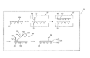
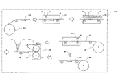
図1に示すように、第1実施形態に係る積層体製造装置10は、無機基板搬送装置20と、無機基板洗浄装置30と、塗布装置40と、水供給装置50と、フィルム洗浄装置60と、ラミネート装置70と、外観検査装置80とを備える。ただし、本発明における積層体製造装置は、少なくとも第1のシート搬送装置(無機基板搬送装置)と、水供給装置と、ラミネート装置とを備えていればよい。
As shown in FIG. 1, the
無機基板搬送装置20は、無機基板100を搬送し、積層体製造装置10が備える各装置間を移動させる。無機基板搬送装置20は、無機基板100を搬送することが可能であれば特に限定されないが、電気駆動式のローラコンベアであることが好ましい。無機基板搬送装置20が電気駆動式のローラコンベアであると、無機基板を順次移動させながら積層体を製造することができる、積層体の製造をオートメーション化することができる。
The inorganic
無機基板洗浄装置30は、洗浄液噴射ノズル32や図示しないエアナイフ等を備える。無機基板洗浄装置30は、無機基板100上に洗浄液34を噴射した後、前記エアナイフで空気を吹き付けることにより、無機基板100の表面を乾燥することができる。なお、本発明に係る第1の洗浄装置(無機基板洗浄装置)は、水性媒体が供給される前の第1のシート(無機基板)を洗浄することが可能な装置であれば、上述した無機基板洗浄装置30に限定されず、従来公知のものを採用することができる。
The inorganic
塗布装置40は、複数の小孔が設けられたシランカップリング剤供給管42等を備える。塗布装置40は、前記シランカップリング剤供給管42から無機基板100上にシランカップリング剤44を塗布することができる。なお、本発明に係る塗布装置は、シランカップリング剤を無機基板へ塗布することが可能な装置であれば、上述した塗布装置40に限定されず、従来公知のものを採用することができる。
The
水供給装置50は、シランカップリング剤が塗布された無機基板100の表面に水性媒体52を供給する。水供給装置50は、シランカップリング剤が塗布された無機基板100の表面に水性媒体52を供給することが可能であれば、特にその構成は限定されず、従来公知のものを採用することができる。水性媒体52の供給量としては、特に限定されないが、気泡、及び、異物低減の観点から、0.1~50g/100cm2程度が好ましい。A
フィルム洗浄装置60は、ロール101から供給される耐熱高分子フィルム102上に洗浄液64を噴射した後、図示しないエアナイフで空気を吹き付けることにより、耐熱高分子フィルム102の表面を洗浄することができる。なお、本発明に係る第2の洗浄装置(フィルム洗浄装置)は、水性媒体が供給される前の第2のシート(耐熱高分子フィルム)を洗浄することが可能な装置であれば、上述したフィルム洗浄装置60に限定されず、従来公知のものを採用することができる。
The
ラミネート装置70は、ラミネートローラー72等を備える。ラミネート装置70は、ラミネートローラー72により押圧することにより、水性媒体52が供給された後の無機基板100と耐熱高分子フィルム102とを貼り合わせる。貼り合わせの際の押し圧力は0.5MPa以下であること好ましい。積層体製造装置10によれば、シランカップリング剤44の少なくとも一部が水性媒体52に溶解した状態で貼り合わせを行うことができるため、ラミネートの際の押し圧力を小さくすることができる。なお、本発明に係るラミネート装置は、水性媒体が供給された後の無機基板と耐熱高分子フィルムとを貼り合わせることが可能な装置であれば、上述したラミネート装置70に限定されず、従来公知のものを採用することができる。
The
ラミネート装置70の押し圧力は、0.5MPa以下が好ましい。シランカップリング剤の少なくとも一部が水性媒体に溶解した状態で貼り合わせを行うことができるため、ラミネートの際の押し圧力を小さくすることができる。前記押し圧力が0.5MPa以下であると、無機基板を破損することを抑制できる。
前記押し圧力の下限は特に限されないが、0.1MPa以上であることが好ましい。0.1MPa以上であると、密着しない部分が生じることや、接着が不充分になることを防止できる。加圧の際の温度としては、好ましくは10℃~60℃、より好ましくは20℃~40℃である。温度が高すぎると、水性溶液が気化して泡を発生するおそれがあり、高分子フィルムにダメージを与えるおそれがあり、温度が低すぎると、密着力が弱くなる傾向がある。特段に温度コントロールをしない室温(室温付近)で実施することでも問題ない。
その後、高温処理(無加圧での高温処理)あるいは高温加圧を行う。前記高温加圧時の押し圧力は、0.5MPa以下が好ましい。前記高温処理時、及び、高温加圧時の温度としては、例えば、80℃以上、より好ましくは100~250℃、さらに好ましくは120~220℃、特に好ましくは90℃~140℃である。高温加圧を行うことにより、密着界面の化学反応が促進されて高分子フィルムと無機基板とを積層できる。The pressing force of the
Although the lower limit of the pressing force is not particularly limited, it is preferably 0.1 MPa or more. When it is 0.1 MPa or more, it is possible to prevent the occurrence of non-adhering portions and insufficient adhesion. The temperature during pressurization is preferably 10°C to 60°C, more preferably 20°C to 40°C. If the temperature is too high, the aqueous solution may vaporize and generate bubbles, which may damage the polymer film. There is no problem even if it is carried out at room temperature (near room temperature) without special temperature control.
After that, high temperature treatment (high temperature treatment without pressure) or high temperature pressurization is performed. The pressing pressure during the high temperature pressurization is preferably 0.5 MPa or less. The temperature during the high temperature treatment and high temperature pressurization is, for example, 80°C or higher, more preferably 100 to 250°C, still more preferably 120 to 220°C, and particularly preferably 90 to 140°C. The high-temperature pressurization accelerates the chemical reaction at the adhered interface, enabling the polymer film and the inorganic substrate to be laminated.
また加圧処理は、大気圧雰囲気中で行うこともできるが、真空下で行ったほうが、接着力の均一性を得ることができる場合がある。真空度としては、通常の油回転ポンプによる真空度で充分であり、10Torr以下程度あれば充分である。
加圧加熱処理に使用することができる装置としては、真空中でのプレスを行うには、例えば井元製作所製の「11FD」等を使用でき、真空中でのロール式のフィルムラミネーターあるいは真空にした後に薄いゴム膜によりガラス全面に一度に圧力を加えるフィルムラミネーター等の真空ラミネートを行うには、例えば名機製作所製の「MVLP」等を使用できる。Also, the pressure treatment can be performed in an atmosphere of atmospheric pressure, but there are cases where the uniformity of the adhesive force can be obtained by performing the pressure treatment in a vacuum. As for the degree of vacuum, a degree of vacuum by a normal oil rotary pump is sufficient, and a degree of 10 Torr or less is sufficient.
As an apparatus that can be used for pressure heating treatment, for example, "11FD" manufactured by Imoto Seisakusho Co., Ltd. can be used for pressing in a vacuum, and a roll-type film laminator in a vacuum or a vacuum is used. For vacuum lamination using a film laminator or the like that applies pressure to the entire glass surface at once with a thin rubber film, for example, "MVLP" manufactured by Meiki Seisakusho Co., Ltd. can be used.
外観検査装置80は、ラミネート装置70によって貼り合わせられた無機基板100と耐熱高分子フィルム102との積層体104の外観を検査する。外観検査装置80としては、例えば、自動光学検査装置(AOI:Automated Optical Inspection)を採用することができる。外観検査装置80は、CCDカメラで得られた画像(積層体104の耐熱高分子フィルム102面側の画像)と予め設定(定量化)されたデータとをもとにして、積層体104に異物の混入がないかや、貼り付けムラがないか等を判定する。なお、本発明に係る外観検査装置は、無機基板と耐熱高分子フィルムとの積層体の外観を検査することが可能な装置であれば、上述した外観検査装置80に限定されず、従来公知のものを採用することができる。
The
また、積層体製造装置10は、図示しない剥離装置を備える。前記剥離装置は、外観検査装置80により外観不良と判定された積層体104から耐熱性高分子フィルム102を剥離する。前記剥離装置としては、従来公知のものを採用することができる。前記剥離装置を備えるため、外観不良と判定された積層体104から耐熱性高分子フィルム102を剥離することができる。その結果、無機基板100をすぐに再利用することが可能となる。
The
上述した実施形態では、シランカップリング剤を無機基板へ塗布する塗布装置40を備える場合について説明したが、本発明ではこの例に限定されず、シランカップリング剤を第1のシート(無機基板)へ塗布する塗布装置40の代わりに、シランカップリング剤を第2のシート(耐熱高分子フィルム)へ塗布する装置を備えることとしてもよい。また、シランカップリング剤を第1のシート(無機基板)へ塗布する塗布装置40を備えるとともに、シランカップリング剤を第2のシート(耐熱高分子フィルム)へ塗布する装置を備えることとしてもよい。
また、上述した実施形態では、シランカップリング剤を無機基板へ塗布する塗布装置40を備える場合について説明したが、本発明ではシランカップリング剤を第1のシート(無機基板)へ塗布する塗布装置を備えなくてもよい。この場合、例えば、予めシランカップリング剤が塗布された第1のシート(無機基板)を用いることとすればよい。In the above-described embodiment, the case where the
In addition, in the above-described embodiment, the case where the
以上、第1実施形態に係る積層体製造装置10について説明した。
The
次に、第1実施形態に係る積層体の製造方法について説明する。以下では、積層体製造装置10を用いた場合の積層体の製造方法について説明するが、本発明ではこの例に限定されない。例えば、各装置で実施される工程を、作業者等が実施することとしてもよい。
Next, a method for manufacturing a laminate according to the first embodiment will be described. A method for manufacturing a laminate using the
第1実施形態に係る積層体の製造方法は、
無機基板、及び、耐熱高分子フィルムをこの順で有する積層体の製造方法であって、
シランカップリング剤が塗布された無機基板の表面に、水性媒体を供給する工程A、及び、
水性媒体が供給された後の無機基板と耐熱高分子フィルムとを貼り合わせる工程B
を少なくとも有する。A method for manufacturing a laminate according to the first embodiment includes:
A method for producing a laminate having an inorganic substrate and a heat-resistant polymer film in this order,
Step A of supplying an aqueous medium to the surface of the inorganic substrate coated with the silane coupling agent, and
Step B of bonding the inorganic substrate and the heat-resistant polymer film after the aqueous medium has been supplied
have at least
前記積層体の製造方法は、さらに、
無機基板を洗浄する工程X-2、
工程X-2の後にシランカップリング剤を無機基板へ塗布する工程X-1
耐熱高分子フィルムを洗浄する工程X-3
前記工程Bの後、貼り合わせられた無機基板と耐熱高分子フィルムとの積層体の外観を検査する工程X-4、及び、
前記工程X-4により外観不良と判定された積層体から耐熱性高分子フィルムを剥離する工程X-5とを有することが好ましい。The method for manufacturing the laminate further comprises:
step X-2 of cleaning the inorganic substrate;
Step X-1 of applying a silane coupling agent to the inorganic substrate after step X-2
Step X-3 of washing the heat-resistant polymer film
After the step B, a step X-4 of inspecting the appearance of the laminate of the laminated inorganic substrate and the heat-resistant polymer film, and
It is preferable to have a step X-5 of peeling the heat-resistant polymer film from the laminate determined to have a poor appearance in the step X-4.
前記積層体の製造方法では、まず、無機基板搬送装置20により無機基板100を無機基板洗浄装置30の方向に移動させ、基板洗浄装置30により無機基板を洗浄する(工程X-2)。
In the method for manufacturing the laminate, first, the
次に、無機基板搬送装置20により無機基板100を塗布装置40の方向に移動させ、を塗布装置40によりシランカップリング剤を無機基板へ塗布する(工程X-1)。
Next, the
一方、フィルム洗浄装置60により、ロール101から供給される耐熱高分子フィルム102上に洗浄液64を噴射した後、図示しないエアナイフで空気を吹き付けることにより、耐熱高分子フィルム102の表面を洗浄する(工程X-3)。
On the other hand, after the cleaning
次に、水供給装置50により、シランカップリング剤が塗布された無機基板100の表面に、水性媒体52を供給する(工程A)。
Next, an
次に、ラミネート装置70により、水性媒体52が供給された後の無機基板100と耐熱高分子フィルム102とを貼り合わせる(工程B)。
Next, the
次に、貼り合わせられた無機基板100と耐熱高分子フィルム102との積層体104の外観を外観検査装置80により検査する(工程X-4)。
Next, the appearance of the
次に、剥離装置により、前記工程X-4により外観不良と判定された積層体104から耐熱性高分子フィルム102を剥離する(工程X-5)。
Next, the heat-
上述した実施形態では、シランカップリング剤を無機基板へ塗布する場合について説明したが、本発明ではこの例に限定されず、シランカップリング剤を第1のシート(無機基板)へ塗布する代わりに、シランカップリング剤を第2のシート(耐熱高分子フィルム)へ塗布することとしてもよい。また、シランカップリング剤を第1のシート(無機基板)へ塗布するとともに、シランカップリング剤を第2のシート(耐熱高分子フィルム)へ塗布することとしてもよい。
また、上述した実施形態では、シランカップリング剤を無機基板へ塗布する場合について説明したが、本発明ではシランカップリング剤を第1のシート(無機基板)へ塗布する工程を備えなくてもよい。この場合、例えば、予めシランカップリング剤が塗布された第1のシート(無機基板)を用いることとすればよい。In the above-described embodiment, the case where the silane coupling agent is applied to the inorganic substrate has been described, but the present invention is not limited to this example, and instead of applying the silane coupling agent to the first sheet (inorganic substrate), Alternatively, the silane coupling agent may be applied to the second sheet (heat-resistant polymer film). Alternatively, the silane coupling agent may be applied to the first sheet (inorganic substrate) and the second sheet (heat-resistant polymer film).
Further, in the above-described embodiment, the case where the silane coupling agent is applied to the inorganic substrate has been described, but in the present invention, the step of applying the silane coupling agent to the first sheet (inorganic substrate) may not be provided. . In this case, for example, a first sheet (inorganic substrate) pre-coated with a silane coupling agent may be used.
以上、第1実施形態に係る積層体の製造方法について説明した。 The method for manufacturing the laminate according to the first embodiment has been described above.
次に、前記耐熱高分子フィルム、前記無機基板、前記シランカップリング剤、前記水性媒体について説明する。 Next, the heat-resistant polymer film, the inorganic substrate, the silane coupling agent, and the aqueous medium will be described.
本明細書において、耐熱高分子とは、融点が250℃以上であることが好ましく、より好ましくは300℃以上であり、融点の上限は特に限定されず、耐熱性高分子の分解温度と同じであっても構わない。また、ガラス転移温度が250℃以上であることが好ましく、より好ましくは320℃以上であり、さらに好ましくは380℃以上であり、好ましくは500℃以下であり、より好ましくは450℃以下の高分子である。以下、煩雑さを避けるために単に高分子とも称する。本明細書において、融点、及び、ガラス転移温度は、示差熱分析(DSC)により求めるものである。なお、融点が500℃を越える場合には、該当温度にて加熱した際の熱変形挙動を目視観察することで融点に達しているか否かを判断して良い。 In this specification, the heat-resistant polymer preferably has a melting point of 250° C. or higher, more preferably 300° C. or higher, and the upper limit of the melting point is not particularly limited. It doesn't matter if there is. Further, the glass transition temperature is preferably 250° C. or higher, more preferably 320° C. or higher, still more preferably 380° C. or higher, preferably 500° C. or lower, and more preferably 450° C. or lower. is. In the following, to avoid complication, it is simply referred to as a polymer. As used herein, the melting point and glass transition temperature are determined by differential thermal analysis (DSC). When the melting point exceeds 500° C., it may be determined whether or not the melting point has been reached by visually observing the thermal deformation behavior when heated at the relevant temperature.
前記耐熱高分子フィルム(以下、単に高分子フィルムとも称する。また単にフィルムとも称する)としては、ポリイミド、ポリアミドイミド、ポリエーテルイミド、フッ素化ポリイミドといったポリイミド系樹脂(例えば、芳香族ポリイミド樹脂、脂環族ポリイミド樹脂);ポリエチレン、ポリプロピレン、ポリエチレンテレフタレート、ポリブチレンテレフタレート、ポリエチレン-2,6-ナフタレートといった共重合ポリエステル(例えば、全芳香族ポリエステル、半芳香族ポリエステル);ポリメチルメタクリレートに代表される共重合(メタ)アクリレート;ポリカーボネート;ポリアミド;ポリスルフォン;ポリエーテルスルフォン;ポリエーテルケトン;酢酸セルロース;硝酸セルロース;芳香族ポリアミド;ポリ塩化ビニル;ポリフェノール;ポリアリレート;ポリフェニレンスルフィド;ポリフェニレンオキシド;ポリスチレン;ポリベンゾオキサゾール(芳香族ポリベンゾオキサゾール);ポリベンゾチアゾール(芳香族ポリベンゾチアゾール);ポリベンゾイミダゾール(芳香族ポリベンゾイミダゾール)等のフィルムを例示できる。
前記高分子フィルムのなかでも好ましくは、所謂スーパーエンジニアリングプラスチックを用いたフィルムであり、より具体的には、芳香族ポリイミドフィルム、芳香族ポリアミドフィルム、芳香族ポリアミドイミドフィルム、芳香族ポリベンゾオキサゾールフィルム、芳香族ポリベンゾチアゾールフィルム、芳香族ポリベンゾイミダゾールフィルム等が挙げられる。The heat-resistant polymer film (hereinafter also simply referred to as a polymer film. Also simply referred to as a film) includes polyimide-based resins such as polyimide, polyamideimide, polyetherimide, and fluorinated polyimide (e.g., aromatic polyimide resin, alicyclic polyimide resin); copolymerized polyesters such as polyethylene, polypropylene, polyethylene terephthalate, polybutylene terephthalate, and polyethylene-2,6-naphthalate (for example, wholly aromatic polyesters and semi-aromatic polyesters); copolymers represented by polymethyl methacrylate (Meth)acrylates; Polycarbonates; Polyamides; Polysulfones; Polyethersulfones; Polyetherketones; Cellulose acetate; Cellulose nitrate; Aromatic polyamides; (aromatic polybenzoxazole); polybenzothiazole (aromatic polybenzothiazole); and polybenzimidazole (aromatic polybenzimidazole).
Among the polymer films, preferred are films using so-called super engineering plastics. More specifically, aromatic polyimide films, aromatic polyamide films, aromatic polyamideimide films, aromatic polybenzoxazole films, Examples include aromatic polybenzothiazole films and aromatic polybenzimidazole films.
以下に前記高分子フィルムの一例であるポリイミド系樹脂フィルム(ポリイミドフィルムと称する場合もある)についての詳細を説明する。一般にポリイミド系樹脂フィルムは、溶媒中でジアミン類とテトラカルボン酸類とを反応させて得られるポリアミド酸(ポリイミド前駆体)溶液を、ポリイミドフィルム作製用支持体に塗布、乾燥してグリーンフィルム(以下では「ポリアミド酸フィルム」ともいう)とし、さらにポリイミドフィルム作製用支持体上で、あるいは該支持体から剥がした状態でグリーンフィルムを高温熱処理して脱水閉環反応を行わせることによって得られる。 The details of a polyimide resin film (also referred to as a polyimide film), which is an example of the polymer film, will be described below. In general, a polyimide resin film is prepared by applying a polyamic acid (polyimide precursor) solution obtained by reacting diamines and tetracarboxylic acids in a solvent to a support for producing a polyimide film and drying it to form a green film (hereinafter referred to as (also referred to as "polyamic acid film"), and further subjecting the green film to a high-temperature heat treatment on a polyimide film-producing support or in a state in which the green film is peeled off from the support to cause a dehydration ring-closing reaction.
ポリアミド酸(ポリイミド前駆体)溶液の塗布は、例えば、スピンコート、ドクターブレード、アプリケーター、コンマコーター、スクリーン印刷法、スリットコート、リバースコート、ディップコート、カーテンコート、スリットダイコート等従来公知の溶液の塗布手段を適宜用いることができる。 Application of the polyamic acid (polyimide precursor) solution includes, for example, spin coating, doctor blade, applicator, comma coater, screen printing method, slit coating, reverse coating, dip coating, curtain coating, slit die coating, etc. Application of conventionally known solutions. means can be used as appropriate.
ポリアミド酸を構成するジアミン類としては、特に制限はなく、ポリイミド合成に通常用いられる芳香族ジアミン類、脂肪族ジアミン類、脂環式ジアミン類等を用いることができる。耐熱性の観点からは、芳香族ジアミン類が好ましく、芳香族ジアミン類の中では、ベンゾオキサゾール構造を有する芳香族ジアミン類がより好ましい。ベンゾオキサゾール構造を有する芳香族ジアミン類を用いると、高い耐熱性とともに、高弾性率、低熱収縮性、低線膨張係数を発現させることが可能になる。ジアミン類は、単独で用いてもよいし二種以上を併用してもよい。 The diamines constituting the polyamic acid are not particularly limited, and aromatic diamines, aliphatic diamines, alicyclic diamines and the like which are commonly used in polyimide synthesis can be used. From the viewpoint of heat resistance, aromatic diamines are preferred, and among aromatic diamines, aromatic diamines having a benzoxazole structure are more preferred. The use of aromatic diamines having a benzoxazole structure makes it possible to exhibit high heat resistance, high elastic modulus, low thermal shrinkage, and low coefficient of linear expansion. Diamines may be used alone or in combination of two or more.
ベンゾオキサゾール構造を有する芳香族ジアミン類としては、特に限定はなく、例えば、5-アミノ-2-(p-アミノフェニル)ベンゾオキサゾール、6-アミノ-2-(p-アミノフェニル)ベンゾオキサゾール、5-アミノ-2-(m-アミノフェニル)ベンゾオキサゾール、6-アミノ-2-(m-アミノフェニル)ベンゾオキサゾール、2,2’-p-フェニレンビス(5-アミノベンゾオキサゾール)、2,2’-p-フェニレンビス(6-アミノベンゾオキサゾール)、1-(5-アミノベンゾオキサゾロ)-4-(6-アミノベンゾオキサゾロ)ベンゼン、2,6-(4,4’-ジアミノジフェニル)ベンゾ[1,2-d:5,4-d’]ビスオキサゾール、2,6-(4,4’-ジアミノジフェニル)ベンゾ[1,2-d:4,5-d’]ビスオキサゾール、2,6-(3,4’-ジアミノジフェニル)ベンゾ[1,2-d:5,4-d’]ビスオキサゾール、2,6-(3,4’-ジアミノジフェニル)ベンゾ[1,2-d:4,5-d’]ビスオキサゾール、2,6-(3,3’-ジアミノジフェニル)ベンゾ[1,2-d:5,4-d’]ビスオキサゾール、2,6-(3,3’-ジアミノジフェニル)ベンゾ[1,2-d:4,5-d’]ビスオキサゾール等が挙げられる。前記ベンゾオキサゾール構造を有する芳香族ジアミン類は単独で使用しても良いし、2種以上を組み合わせても良い。 Aromatic diamines having a benzoxazole structure are not particularly limited, and examples include 5-amino-2-(p-aminophenyl)benzoxazole, 6-amino-2-(p-aminophenyl)benzoxazole, 5 -amino-2-(m-aminophenyl)benzoxazole, 6-amino-2-(m-aminophenyl)benzoxazole, 2,2'-p-phenylenebis(5-aminobenzoxazole), 2,2' -p-phenylenebis(6-aminobenzoxazole), 1-(5-aminobenzoxazolo)-4-(6-aminobenzoxazolo)benzene, 2,6-(4,4'-diaminodiphenyl)benzo [1,2-d:5,4-d′]bisoxazole, 2,6-(4,4′-diaminodiphenyl)benzo[1,2-d:4,5-d′]bisoxazole, 2, 6-(3,4′-diaminodiphenyl)benzo[1,2-d:5,4-d′]bisoxazole, 2,6-(3,4′-diaminodiphenyl)benzo[1,2-d: 4,5-d']bisoxazole, 2,6-(3,3'-diaminodiphenyl)benzo[1,2-d:5,4-d']bisoxazole, 2,6-(3,3' -diaminodiphenyl)benzo[1,2-d:4,5-d']bisoxazole and the like. The aromatic diamines having a benzoxazole structure may be used alone or in combination of two or more.
上述したベンゾオキサゾール構造を有する芳香族ジアミン類以外の芳香族ジアミン類としては、例えば、2,2’-ジメチル-4,4’-ジアミノビフェニル、1,4-ビス[2-(4-アミノフェニル)-2-プロピル]ベンゼン(ビスアニリン)、1,4-ビス(4-アミノ-2-トリフルオロメチルフェノキシ)ベンゼン、2,2’-ジトリフルオロメチル-4,4’-ジアミノビフェニル、4,4’-ビス(4-アミノフェノキシ)ビフェニル、4,4’-ビス(3-アミノフェノキシ)ビフェニル、ビス[4-(3-アミノフェノキシ)フェニル]ケトン、ビス[4-(3-アミノフェノキシ)フェニル]スルフィド、ビス[4-(3-アミノフェノキシ)フェニル]スルホン、2,2-ビス[4-(3-アミノフェノキシ)フェニル]プロパン、2,2-ビス[4-(3-アミノフェノキシ)フェニル]-1,1,1,3,3,3-ヘキサフルオロプロパン、m-フェニレンジアミン、o-フェニレンジアミン、p-フェニレンジアミン、m-アミノベンジルアミン、p-アミノベンジルアミン、3,3’-ジアミノジフェニルエーテル、3,4’-ジアミノジフェニルエーテル、4,4’-ジアミノジフェニルエーテル、3,3’-ジアミノジフェニルスルフィド、3,3’-ジアミノジフェニルスルホキシド、3,4’-ジアミノジフェニルスルホキシド、4,4’-ジアミノジフェニルスルホキシド、3,3’-ジアミノジフェニルスルホン、3,4’-ジアミノジフェニルスルホン、4,4’-ジアミノジフェニルスルホン、3,3’-ジアミノベンゾフェノン、3,4’-ジアミノベンゾフェノン、4,4’-ジアミノベンゾフェノン、3,3’-ジアミノジフェニルメタン、3,4’-ジアミノジフェニルメタン、4,4’-ジアミノジフェニルメタン、ビス[4-(4-アミノフェノキシ)フェニル]メタン、1,1-ビス[4-(4-アミノフェノキシ)フェニル]エタン、1,2-ビス[4-(4-アミノフェノキシ)フェニル]エタン、1,1-ビス[4-(4-アミノフェノキシ)フェニル]プロパン、1,2-ビス[4-(4-アミノフェノキシ)フェニル]プロパン、1,3-ビス[4-(4-アミノフェノキシ)フェニル]プロパン、2,2-ビス[4-(4-アミノフェノキシ)フェニル]プロパン、1,1-ビス[4-(4-アミノフェノキシ)フェニル]ブタン、1,3-ビス[4-(4-アミノフェノキシ)フェニル]ブタン、1,4-ビス[4-(4-アミノフェノキシ)フェニル]ブタン、2,2-ビス[4-(4-アミノフェノキシ)フェニル]ブタン、2,3-ビス[4-(4-アミノフェノキシ)フェニル]ブタン、2-[4-(4-アミノフェノキシ)フェニル]-2-[4-(4-アミノフェノキシ)-3-メチルフェニル]プロパン、2,2-ビス[4-(4-アミノフェノキシ)-3-メチルフェニル]プロパン、2-[4-(4-アミノフェノキシ)フェニル]-2-[4-(4-アミノフェノキシ)-3,5-ジメチルフェニル]プロパン、2,2-ビス[4-(4-アミノフェノキシ)-3,5-ジメチルフェニル]プロパン、2,2-ビス[4-(4-アミノフェノキシ)フェニル]-1,1,1,3,3,3-ヘキサフルオロプロパン、1,4-ビス(3-アミノフェノキシ)ベンゼン、1,3-ビス(3-アミノフェノキシ)ベンゼン、1,4-ビス(4-アミノフェノキシ)ベンゼン、4,4’-ビス(4-アミノフェノキシ)ビフェニル、ビス[4-(4-アミノフェノキシ)フェニル]ケトン、ビス[4-(4-アミノフェノキシ)フェニル]スルフィド、ビス[4-(4-アミノフェノキシ)フェニル]スルホキシド、ビス[4-(4-アミノフェノキシ)フェニル]スルホン、ビス[4-(3-アミノフェノキシ)フェニル]エーテル、ビス[4-(4-アミノフェノキシ)フェニル]エーテル、1,3-ビス[4-(4-アミノフェノキシ)ベンゾイル]ベンゼン、1,3-ビス[4-(3-アミノフェノキシ)ベンゾイル]ベンゼン、1,4-ビス[4-(3-アミノフェノキシ)ベンゾイル]ベンゼン、4,4’-ビス[(3-アミノフェノキシ)ベンゾイル]ベンゼン、1,1-ビス[4-(3-アミノフェノキシ)フェニル]プロパン、1,3-ビス[4-(3-アミノフェノキシ)フェニル]プロパン、3,4’-ジアミノジフェニルスルフィド、2,2-ビス[3-(3-アミノフェノキシ)フェニル]-1,1,1,3,3,3-ヘキサフルオロプロパン、ビス[4-(3-アミノフェノキシ)フェニル]メタン、1,1-ビス[4-(3-アミノフェノキシ)フェニル]エタン、1,2-ビス[4-(3-アミノフェノキシ)フェニル]エタン、ビス[4-(3-アミノフェノキシ)フェニル]スルホキシド、4,4’-ビス[3-(4-アミノフェノキシ)ベンゾイル]ジフェニルエーテル、4,4’-ビス[3-(3-アミノフェノキシ)ベンゾイル]ジフェニルエーテル、4,4’-ビス[4-(4-アミノ-α,α-ジメチルベンジル)フェノキシ]ベンゾフェノン、4,4’-ビス[4-(4-アミノ-α,α-ジメチルベンジル)フェノキシ]ジフェニルスルホン、ビス[4-{4-(4-アミノフェノキシ)フェノキシ}フェニル]スルホン、1,4-ビス[4-(4-アミノフェノキシ)フェノキシ-α,α-ジメチルベンジル]ベンゼン、1,3-ビス[4-(4-アミノフェノキシ)フェノキシ-α,α-ジメチルベンジル]ベンゼン、1,3-ビス[4-(4-アミノ-6-トリフルオロメチルフェノキシ)-α,α-ジメチルベンジル]ベンゼン、1,3-ビス[4-(4-アミノ-6-フルオロフェノキシ)-α,α-ジメチルベンジル]ベンゼン、1,3-ビス[4-(4-アミノ-6-メチルフェノキシ)-α,α-ジメチルベンジル]ベンゼン、1,3-ビス[4-(4-アミノ-6-シアノフェノキシ)-α,α-ジメチルベンジル]ベンゼン、3,3’-ジアミノ-4,4’-ジフェノキシベンゾフェノン、4,4’-ジアミノ-5,5’-ジフェノキシベンゾフェノン、3,4’-ジアミノ-4,5’-ジフェノキシベンゾフェノン、3,3’-ジアミノ-4-フェノキシベンゾフェノン、4,4’-ジアミノ-5-フェノキシベンゾフェノン、3,4’-ジアミノ-4-フェノキシベンゾフェノン、3,4’-ジアミノ-5’-フェノキシベンゾフェノン、3,3’-ジアミノ-4,4’-ジビフェノキシベンゾフェノン、4,4’-ジアミノ-5,5’-ジビフェノキシベンゾフェノン、3,4’-ジアミノ-4,5’-ジビフェノキシベンゾフェノン、3,3’-ジアミノ-4-ビフェノキシベンゾフェノン、4,4’-ジアミノ-5-ビフェノキシベンゾフェノン、3,4’-ジアミノ-4-ビフェノキシベンゾフェノン、3,4’-ジアミノ-5’-ビフェノキシベンゾフェノン、1,3-ビス(3-アミノ-4-フェノキシベンゾイル)ベンゼン、1,4-ビス(3-アミノ-4-フェノキシベンゾイル)ベンゼン、1,3-ビス(4-アミノ-5-フェノキシベンゾイル)ベンゼン、1,4-ビス(4-アミノ-5-フェノキシベンゾイル)ベンゼン、1,3-ビス(3-アミノ-4-ビフェノキシベンゾイル)ベンゼン、1,4-ビス(3-アミノ-4-ビフェノキシベンゾイル)ベンゼン、1,3-ビス(4-アミノ-5-ビフェノキシベンゾイル)ベンゼン、1,4-ビス(4-アミノ-5-ビフェノキシベンゾイル)ベンゼン、2,6-ビス[4-(4-アミノ-α,α-ジメチルベンジル)フェノキシ]ベンゾニトリル等が挙げられる。また、前記芳香族ジアミンの芳香環上の水素原子の一部もしくは全てが、ハロゲン原子、炭素数1~3のアルキル基もしくはアルコキシル基、またはシアノ基で置換されていても良く、さらに前記炭素数1~3のアルキル基もしくはアルコキシル基の水素原子の一部もしくは全部がハロゲン原子で置換されていても良い。なお、前記芳香族ジアミン類は単独で使用しても良いし、2種以上を組み合わせても良い。 Examples of aromatic diamines other than the above aromatic diamines having a benzoxazole structure include 2,2′-dimethyl-4,4′-diaminobiphenyl, 1,4-bis[2-(4-aminophenyl )-2-propyl]benzene (bisaniline), 1,4-bis(4-amino-2-trifluoromethylphenoxy)benzene, 2,2′-ditrifluoromethyl-4,4′-diaminobiphenyl, 4,4 '-bis(4-aminophenoxy)biphenyl, 4,4'-bis(3-aminophenoxy)biphenyl, bis[4-(3-aminophenoxy)phenyl]ketone, bis[4-(3-aminophenoxy)phenyl ] sulfide, bis[4-(3-aminophenoxy)phenyl]sulfone, 2,2-bis[4-(3-aminophenoxy)phenyl]propane, 2,2-bis[4-(3-aminophenoxy)phenyl ]-1,1,1,3,3,3-hexafluoropropane, m-phenylenediamine, o-phenylenediamine, p-phenylenediamine, m-aminobenzylamine, p-aminobenzylamine, 3,3′- Diaminodiphenyl ether, 3,4'-diaminodiphenyl ether, 4,4'-diaminodiphenyl ether, 3,3'-diaminodiphenyl sulfide, 3,3'-diaminodiphenyl sulfoxide, 3,4'-diaminodiphenyl sulfoxide, 4,4' -diaminodiphenyl sulfoxide, 3,3'-diaminodiphenyl sulfone, 3,4'-diaminodiphenyl sulfone, 4,4'-diaminodiphenyl sulfone, 3,3'-diaminobenzophenone, 3,4'-diaminobenzophenone, 4, 4'-diaminobenzophenone, 3,3'-diaminodiphenylmethane, 3,4'-diaminodiphenylmethane, 4,4'-diaminodiphenylmethane, bis[4-(4-aminophenoxy)phenyl]methane, 1,1-bis[ 4-(4-aminophenoxy)phenyl]ethane, 1,2-bis[4-(4-aminophenoxy)phenyl]ethane, 1,1-bis[4-(4-aminophenoxy)phenyl]propane, 1, 2-bis[4-(4-aminophenoxy)phenyl]propane, 1,3-bis[4-(4-aminophenoxy)phenyl]propane, 2,2-bis[4-(4-aminophenoxy)phenyl] Propane, 1,1-bis[4-(4-aminophenoxy)phenyl]butane, 1,3- bis[4-(4-aminophenoxy)phenyl]butane, 1,4-bis[4-(4-aminophenoxy)phenyl]butane, 2,2-bis[4-(4-aminophenoxy)phenyl]butane, 2,3-bis[4-(4-aminophenoxy)phenyl]butane, 2-[4-(4-aminophenoxy)phenyl]-2-[4-(4-aminophenoxy)-3-methylphenyl]propane , 2,2-bis[4-(4-aminophenoxy)-3-methylphenyl]propane, 2-[4-(4-aminophenoxy)phenyl]-2-[4-(4-aminophenoxy)-3 ,5-dimethylphenyl]propane, 2,2-bis[4-(4-aminophenoxy)-3,5-dimethylphenyl]propane, 2,2-bis[4-(4-aminophenoxy)phenyl]-1 , 1,1,3,3,3-hexafluoropropane, 1,4-bis(3-aminophenoxy)benzene, 1,3-bis(3-aminophenoxy)benzene, 1,4-bis(4-amino phenoxy)benzene, 4,4'-bis(4-aminophenoxy)biphenyl, bis[4-(4-aminophenoxy)phenyl]ketone, bis[4-(4-aminophenoxy)phenyl]sulfide, bis[4- (4-aminophenoxy)phenyl]sulfoxide, bis[4-(4-aminophenoxy)phenyl]sulfone, bis[4-(3-aminophenoxy)phenyl]ether, bis[4-(4-aminophenoxy)phenyl] ether, 1,3-bis[4-(4-aminophenoxy)benzoyl]benzene, 1,3-bis[4-(3-aminophenoxy)benzoyl]benzene, 1,4-bis[4-(3-amino phenoxy)benzoyl]benzene, 4,4'-bis[(3-aminophenoxy)benzoyl]benzene, 1,1-bis[4-(3-aminophenoxy)phenyl]propane, 1,3-bis[4-( 3-aminophenoxy)phenyl]propane, 3,4′-diaminodiphenyl sulfide, 2,2-bis[3-(3-aminophenoxy)phenyl]-1,1,1,3,3,3-hexafluoropropane , bis[4-(3-aminophenoxy)phenyl]methane, 1,1-bis[4-(3-aminophenoxy)phenyl]ethane, 1,2-bis[4-(3-aminophenoxy)phenyl]ethane , bis[4-(3-aminophenoxy)phenyl]sulfoxide, 4,4′-bis[ 3-(4-aminophenoxy)benzoyl]diphenyl ether, 4,4'-bis[3-(3-aminophenoxy)benzoyl]diphenyl ether, 4,4'-bis[4-(4-amino-α,α-dimethyl benzyl)phenoxy]benzophenone, 4,4′-bis[4-(4-amino-α,α-dimethylbenzyl)phenoxy]diphenylsulfone, bis[4-{4-(4-aminophenoxy)phenoxy}phenyl]sulfone , 1,4-bis[4-(4-aminophenoxy)phenoxy-α,α-dimethylbenzyl]benzene, 1,3-bis[4-(4-aminophenoxy)phenoxy-α,α-dimethylbenzyl]benzene , 1,3-bis[4-(4-amino-6-trifluoromethylphenoxy)-α,α-dimethylbenzyl]benzene, 1,3-bis[4-(4-amino-6-fluorophenoxy)- α,α-dimethylbenzyl]benzene, 1,3-bis[4-(4-amino-6-methylphenoxy)-α,α-dimethylbenzyl]benzene, 1,3-bis[4-(4-amino- 6-cyanophenoxy)-α,α-dimethylbenzyl]benzene, 3,3′-diamino-4,4′-diphenoxybenzophenone, 4,4′-diamino-5,5′-diphenoxybenzophenone, 3,4 '-diamino-4,5'-diphenoxybenzophenone, 3,3'-diamino-4-phenoxybenzophenone, 4,4'-diamino-5-phenoxybenzophenone, 3,4'-diamino-4-phenoxybenzophenone, 3 ,4'-diamino-5'-phenoxybenzophenone, 3,3'-diamino-4,4'-dibiphenoxybenzophenone, 4,4'-diamino-5,5'-dibiphenoxybenzophenone, 3,4'-diamino -4,5'-dibiphenoxybenzophenone, 3,3'-diamino-4-biphenoxybenzophenone, 4,4'-diamino-5-biphenoxybenzophenone, 3,4'-diamino-4-biphenoxybenzophenone, 3 ,4'-diamino-5'-biphenoxybenzophenone, 1,3-bis(3-amino-4-phenoxybenzoyl)benzene, 1,4-bis(3-amino-4-phenoxybenzoyl)benzene, 1,3 -bis(4-amino-5-phenoxybenzoyl)benzene, 1,4-bis(4-amino-5-phenoxybenzoyl)benzene, 1,3-bis(3-amino-4-biphenyl noxybenzoyl)benzene, 1,4-bis(3-amino-4-biphenoxybenzoyl)benzene, 1,3-bis(4-amino-5-biphenoxybenzoyl)benzene, 1,4-bis(4- amino-5-biphenoxybenzoyl)benzene, 2,6-bis[4-(4-amino-α,α-dimethylbenzyl)phenoxy]benzonitrile and the like. In addition, some or all of the hydrogen atoms on the aromatic ring of the aromatic diamine may be substituted with a halogen atom, an alkyl group or alkoxyl group having 1 to 3 carbon atoms, or a cyano group, and Some or all of the hydrogen atoms in 1 to 3 alkyl or alkoxyl groups may be substituted with halogen atoms. Incidentally, the aromatic diamines may be used singly or in combination of two or more.
前記脂肪族ジアミン類としては、例えば、1,2-ジアミノエタン、1,4-ジアミノブタン、1,5-ジアミノペンタン、1,6-ジアミノヘキサン、1,8-ジアミノオタン等が挙げられる。
前記脂環式ジアミン類としては、例えば、1,4-ジアミノシクロヘキサン、4,4’-メチレンビス(2,6-ジメチルシクロヘキシルアミン)等が挙げられる。
芳香族ジアミン類以外のジアミン(脂肪族ジアミン類および脂環式ジアミン類)の合計量は、全ジアミン類の20質量%以下が好ましく、より好ましくは10質量%以下、さらに好ましくは5質量%以下である。換言すれば、芳香族ジアミン類は全ジアミン類の80質量%以上が好ましく、より好ましくは90質量%以上、さらに好ましくは95質量%以上である。Examples of the aliphatic diamines include 1,2-diaminoethane, 1,4-diaminobutane, 1,5-diaminopentane, 1,6-diaminohexane, 1,8-diaminooctane and the like.
Examples of the alicyclic diamines include 1,4-diaminocyclohexane and 4,4'-methylenebis(2,6-dimethylcyclohexylamine).
The total amount of diamines other than aromatic diamines (aliphatic diamines and alicyclic diamines) is preferably 20% by mass or less, more preferably 10% by mass or less, and still more preferably 5% by mass or less of all diamines. is. In other words, aromatic diamines are preferably 80% by mass or more, more preferably 90% by mass or more, and still more preferably 95% by mass or more of all diamines.
ポリアミド酸を構成するテトラカルボン酸類としては、ポリイミド合成に通常用いられる芳香族テトラカルボン酸類(その酸無水物を含む)、脂肪族テトラカルボン酸類(その酸無水物を含む)、脂環族テトラカルボン酸類(その酸無水物を含む)を用いることができる。中でも、芳香族テトラカルボン酸無水物類、脂環族テトラカルボン酸無水物類が好ましく、耐熱性の観点からは芳香族テトラカルボン酸無水物類がより好ましく、光透過性の観点からは脂環族テトラカルボン酸類がより好ましい。これらが酸無水物である場合、分子内に無水物構造は1個であってもよいし2個であってもよいが、好ましくは2個の無水物構造を有するもの(二無水物)がよい。テトラカルボン酸類は単独で用いてもよいし、二種以上を併用してもよい。 Tetracarboxylic acids constituting polyamic acid include aromatic tetracarboxylic acids (including their acid anhydrides), aliphatic tetracarboxylic acids (including their acid anhydrides), and alicyclic tetracarboxylic acids, which are commonly used in polyimide synthesis. Acids (including anhydrides thereof) can be used. Among them, aromatic tetracarboxylic anhydrides and alicyclic tetracarboxylic anhydrides are preferable, aromatic tetracarboxylic anhydrides are more preferable from the viewpoint of heat resistance, and alicyclic anhydrides are preferable from the viewpoint of light transmittance. Group tetracarboxylic acids are more preferred. When these are acid anhydrides, one or two anhydride structures may be present in the molecule, but preferably those having two anhydride structures (dianhydrides) are good. Tetracarboxylic acids may be used alone, or two or more of them may be used in combination.
脂環族テトラカルボン酸類としては、例えば、シクロブタンテトラカルボン酸、1,2,4,5-シクロヘキサンテトラカルボン酸、3,3’,4,4’-ビシクロヘキシルテトラカルボン酸等の脂環族テトラカルボン酸、およびこれらの酸無水物が挙げられる。これらの中でも、2個の無水物構造を有する二無水物(例えば、シクロブタンテトラカルボン酸二無水物、1,2,4,5-シクロヘキサンテトラカルボン酸二無水物、3,3’,4,4’-ビシクロヘキシルテトラカルボン酸二無水物等)が好適である。なお、脂環族テトラカルボン酸類は単独で用いてもよいし、二種以上を併用してもよい。
脂環式テトラカルボン酸類は、透明性を重視する場合には、例えば、全テトラカルボン酸類の80質量%以上が好ましく、より好ましくは90質量%以上、さらに好ましくは95質量%以上である。Examples of alicyclic tetracarboxylic acids include alicyclic tetracarboxylic acids such as cyclobutanetetracarboxylic acid, 1,2,4,5-cyclohexanetetracarboxylic acid, and 3,3′,4,4′-bicyclohexyltetracarboxylic acid. Carboxylic acids, and their acid anhydrides. Among these, dianhydrides having two anhydride structures (for example, cyclobutanetetracarboxylic dianhydride, 1,2,4,5-cyclohexanetetracarboxylic dianhydride, 3,3′,4,4 '-bicyclohexyltetracarboxylic dianhydride) are preferred. The alicyclic tetracarboxylic acids may be used alone, or two or more of them may be used in combination.
The alicyclic tetracarboxylic acid is, for example, preferably 80% by mass or more, more preferably 90% by mass or more, and still more preferably 95% by mass or more of the total tetracarboxylic acids when transparency is important.
芳香族テトラカルボン酸類としては、特に限定されないが、ピロメリット酸残基(すなわちピロメリット酸由来の構造を有するもの)であることが好ましく、その酸無水物であることがより好ましい。このような芳香族テトラカルボン酸類としては、例えば、ピロメリット酸二無水物、3,3’,4,4’-ビフェニルテトラカルボン酸二無水物、4,4’-オキシジフタル酸二無水物、3,3’,4,4’-ベンゾフェノンテトラカルボン酸二無水物、3,3’,4,4’-ジフェニルスルホンテトラカルボン酸二無水物、2,2-ビス[4-(3,4-ジカルボキシフェノキシ)フェニル]プロパン酸無水物、4,4’-(2,2-ヘキサフルオロイソプロピリデン)ジフタル酸二無水物等が挙げられる。
芳香族テトラカルボン酸類は、耐熱性を重視する場合には、例えば、全テトラカルボン酸類の80質量%以上が好ましく、より好ましくは90質量%以上、さらに好ましくは95質量%以上である。The aromatic tetracarboxylic acid is not particularly limited, but is preferably a pyromellitic acid residue (that is, having a structure derived from pyromellitic acid), more preferably an acid anhydride thereof. Examples of such aromatic tetracarboxylic acids include pyromellitic dianhydride, 3,3′,4,4′-biphenyltetracarboxylic dianhydride, 4,4′-oxydiphthalic dianhydride, 3 ,3′,4,4′-benzophenonetetracarboxylic dianhydride, 3,3′,4,4′-diphenylsulfonetetracarboxylic dianhydride, 2,2-bis[4-(3,4-di Carboxyphenoxy)phenyl]propanoic anhydride, 4,4'-(2,2-hexafluoroisopropylidene)diphthalic dianhydride and the like.
The aromatic tetracarboxylic acid is, for example, preferably 80% by mass or more, more preferably 90% by mass or more, and still more preferably 95% by mass or more of the total tetracarboxylic acids when heat resistance is important.
前記ポリイミド系樹脂は、用途によっては透明であることが好ましい場合がある。その前駆体の合成に用いられる酸成分として1,2,3,4-シクロブタンテトラカルボン酸二無水物、1,2,4,5-シクロペンタンテトラカルボン酸二無水物、1,2,4,5-シクロヘキサンテトラカルボン酸二無水物、ビシクロ[2,2,1]ヘプタン-2,3,5,6-テトラカルボン酸二無水物、ビシクロ[2,2,2]オクタン-2,3,5,6-テトラカルボン酸二無水物、3,3’,4,4’-ビシクロヘキシルテトラカルボン酸二無水物、1,2,4-シクロヘキサントリカルボン酸無水物などが例示されるが、特に好ましいのは1,2,3,4-シクロブタンテトラカルボン酸二無水物、1,2,4,5-シクロヘキサンテトラカルボン酸二無水物、3,3’,4,4’-ビシクロヘキシルテトラカルボン酸二無水物である。これらの脂環族カルボン酸類は単独で用いてもよいし、二種以上を併用してもよい。一方、ビシクロ[2,2,2]オクト-7-エン-2,3,5,6-テトラカルボン酸二無水物などの不飽和結合を含むものは加熱処理時に着色し、フィルムの光学特性を低下させる傾向があるため、透明性の観点からは好ましくない。 Depending on the application, the polyimide resin may preferably be transparent. 1,2,3,4-Cyclobutanetetracarboxylic dianhydride, 1,2,4,5-cyclopentanetetracarboxylic dianhydride, 1,2,4, 5-cyclohexanetetracarboxylic dianhydride, bicyclo[2,2,1]heptane-2,3,5,6-tetracarboxylic dianhydride, bicyclo[2,2,2]octane-2,3,5 ,6-tetracarboxylic dianhydride, 3,3′,4,4′-bicyclohexyltetracarboxylic dianhydride, 1,2,4-cyclohexanetricarboxylic anhydride and the like, but particularly preferred are is 1,2,3,4-cyclobutanetetracarboxylic dianhydride, 1,2,4,5-cyclohexanetetracarboxylic dianhydride, 3,3′,4,4′-bicyclohexyltetracarboxylic dianhydride It is a thing. These alicyclic carboxylic acids may be used alone, or two or more of them may be used in combination. On the other hand, those containing unsaturated bonds such as bicyclo[2,2,2]oct-7-ene-2,3,5,6-tetracarboxylic dianhydride are colored during heat treatment, and the optical properties of the film are improved. Since it tends to decrease, it is not preferable from the viewpoint of transparency.
前記透明ポリイミド系樹脂またはその前駆体の合成に用いられるジアミン成分をジアミン化合物として例示すると、1,3-フェニレンジアミン、1,4-フェニレンジアミン、2,4-ジアミノトルエン、2,6-ジアミノトルエン、3,4-ジアミノトルエン、4,5-ジメチル-1,2-フェニレンジアミン、2,5-ジメチル-1,4-フェニレンジアミン、2,6-ジメチル-1,4-フェニレンジアミン、2,3,5,6-テトラメチル-1,4-フェニレンジアミン、3-アミノベンジルアミン、m-キシリレンジアミン、p-キシリレンジアミン、1,5-ジアミノナフタレン、2,2’-ジメチルビフェニル-4,4’-ジアミン、2,2’-ビス(トリフルオロメチル)ベンジジン、3,3’-ジメトキシベンジジン、4,4’-ジアミノオクタフルオロビフェニル、3,3’-ジアミノジフェニルメタン、3,4’-ジアミノジフェニルメタン、4,4’-ジアミノジフェニルメタン、4,4’-メチレンビス(2,6-ジエチルアニリン)、4,4’-メチレンビス(2-エチル-6-メチルアニリン)、4,4’-エチレンジアニリン、4,4’-ジアミノジフェニルエーテル、3,4’-ジアミノジフェニルエーテル、3,3’-ジアミノジフェニルエーテル、2,2’-ビス(トリフルオロメチル)-4,4’-ジアミノジフェニルエーテル、1,3-ビス(4-アミノフェノキシ)ベンゼン、1,3-ビス(3-アミノフェノキシ)ベンゼン、1,4-ビス(4-アミノフェノキシ)ベンゼン、1,4-ビス(4-アミノ-2-トリフルオロメチルフェノキシ)ベンゼン、4,4’-ビス(4-アミノフェノキシ)ビフェニル、4,4’-ジアミノ-3,3’-ジメチルジフェニルメタン、ビス[4-(4-アミノフェノキシ)フェニル]スルフォン、ビス[4-(3-アミノフェノキシ)フェニル]スルフォン、2,2-ビス(4-アミノフェニル)ヘキサフルオロプロパン、2,2-ビス(3-アミノフェニル)ヘキサフルオロプロパン、2,2’-ビス[4-(4-アミノフェノキシ)フェニル]プロパン、2,2’-ビス[4-(4-アミノフェノキシ)フェニル]ヘキサフルオロプロパン、2,2-ビス(3-アミノ-4-メチルフェニル)ヘキサフルオロプロパン、α,α’-ビス(4-アミノフェニル)-1,4-ジイソプロピルベンゼン、ビス(2-アミノフェニル)スルフィド、ビス(4-アミノフェニル)スルフィド、3,3’-ジアミノジフェニルスルフォン、4,4’-ジアミノジフェニルスルフォン、4,4’-ジアミノジフェニルスルフィド、4,4’-ジアミノベンゾフェノン、3,3’-ジアミノベンゾフェノン、4,4’-ジアミノベンズアニリド、1,4-ビス(4-アミノフェノキシ)ベンゼン、ビス(4-アミノフェニル)テレフタレート、2,7-ジアミノフルオレン、9,9-ビス(4-アミノフェニル)フルオレンなどの芳香族ジアミンが挙げられる。また脂環族ジアミンとして1,3-ジアミノシクロヘキサン、1,4-ジアミノシクロヘキサン、1,3-ビス(アミノメチル)シクロヘキサン、1,1-ビス(4-アミノフェニル)シクロヘキサン、4,4’-ジアミノジシクロヘキシルメタン、4,4’-メチレンビス(2-メチルシクロヘキシルアミン)、4,4’-メチレンビス(2,6-ジメチルシクロヘキシルアミン)、4,4’-ジアミノジシクロヘキシルプロパン、ビシクロ[2.2.1]ヘプタン-2,3-ジアミン、ビシクロ[2.2.1]ヘプタン-2,5-ジアミン、ビシクロ[2.2.1]ヘプタン-2,6-ジアミン、ビシクロ[2.2.1]ヘプタン-2,7-ジアミン、2,3-ビス(アミノメチル)-ビシクロ[2.2.1]ヘプタン、2,5-ビス(アミノメチル)-ビシクロ[2.2.1]ヘプタン、2,6-ビス(アミノメチル)-ビシクロ[2.2.1]ヘプタン、3(4),8(9)-ビス(アミノメチル)トリシクロ[5.2.1.0(2,6)]デカンなどが例示される。これらの中で特に好ましいのはp-フェニレンジアミン、2,2’-ジメチルビフェニル-4,4’-ジアミン、2,2’-ビス(トリフルオロメチル)ベンジジン、2,2’-ビス(トリフルオロメチル)-4,4’-ジアミノジフェニルエーテル、1,4-ビス(4-アミノ-2-トリフルオロメチルフェノキシ)ベンゼン、1,4-ジアミノシクロヘキサン、4,4’-ジアミノジシクロヘキシルメタン、4,4’-メチレンビス(2-メチルシクロヘキシルアミン)、4,4’-メチレンビス(2,6-ジメチルシクロヘキシルアミン)である。上記アミン成分は単独で用いてもよいし、二種以上を併用してもよい。 Examples of the diamine component used in synthesizing the transparent polyimide resin or its precursor include 1,3-phenylenediamine, 1,4-phenylenediamine, 2,4-diaminotoluene, and 2,6-diaminotoluene. , 3,4-diaminotoluene, 4,5-dimethyl-1,2-phenylenediamine, 2,5-dimethyl-1,4-phenylenediamine, 2,6-dimethyl-1,4-phenylenediamine, 2,3 , 5,6-tetramethyl-1,4-phenylenediamine, 3-aminobenzylamine, m-xylylenediamine, p-xylylenediamine, 1,5-diaminonaphthalene, 2,2′-dimethylbiphenyl-4, 4'-diamine, 2,2'-bis(trifluoromethyl)benzidine, 3,3'-dimethoxybenzidine, 4,4'-diaminooctafluorobiphenyl, 3,3'-diaminodiphenylmethane, 3,4'-diamino Diphenylmethane, 4,4'-diaminodiphenylmethane, 4,4'-methylenebis(2,6-diethylaniline), 4,4'-methylenebis(2-ethyl-6-methylaniline), 4,4'-ethylenedianiline , 4,4′-diaminodiphenyl ether, 3,4′-diaminodiphenyl ether, 3,3′-diaminodiphenyl ether, 2,2′-bis(trifluoromethyl)-4,4′-diaminodiphenyl ether, 1,3-bis (4-aminophenoxy)benzene, 1,3-bis(3-aminophenoxy)benzene, 1,4-bis(4-aminophenoxy)benzene, 1,4-bis(4-amino-2-trifluoromethylphenoxy) ) benzene, 4,4′-bis(4-aminophenoxy)biphenyl, 4,4′-diamino-3,3′-dimethyldiphenylmethane, bis[4-(4-aminophenoxy)phenyl]sulfone, bis[4- (3-aminophenoxy)phenyl]sulfone, 2,2-bis(4-aminophenyl)hexafluoropropane, 2,2-bis(3-aminophenyl)hexafluoropropane, 2,2′-bis[4-( 4-aminophenoxy)phenyl]propane, 2,2′-bis[4-(4-aminophenoxy)phenyl]hexafluoropropane, 2,2-bis(3-amino-4-methylphenyl)hexafluoropropane, α , α'-bis(4-aminophenyl)-1,4-diisopropylbenzene, bis(2-aminophenyl)s sulfide, bis(4-aminophenyl)sulfide, 3,3'-diaminodiphenylsulfone, 4,4'-diaminodiphenylsulfone, 4,4'-diaminodiphenylsulfide, 4,4'-diaminobenzophenone, 3,3' -diaminobenzophenone, 4,4'-diaminobenzanilide, 1,4-bis(4-aminophenoxy)benzene, bis(4-aminophenyl)terephthalate, 2,7-diaminofluorene, 9,9-bis(4- Aromatic diamines such as aminophenyl)fluorene. 1,3-diaminocyclohexane, 1,4-diaminocyclohexane, 1,3-bis(aminomethyl)cyclohexane, 1,1-bis(4-aminophenyl)cyclohexane, 4,4'-diamino as alicyclic diamines Dicyclohexylmethane, 4,4′-methylenebis(2-methylcyclohexylamine), 4,4′-methylenebis(2,6-dimethylcyclohexylamine), 4,4′-diaminodicyclohexylpropane, bicyclo[2.2.1] Heptane-2,3-diamine, bicyclo[2.2.1]heptane-2,5-diamine, bicyclo[2.2.1]heptane-2,6-diamine, bicyclo[2.2.1]heptane- 2,7-diamine, 2,3-bis(aminomethyl)-bicyclo[2.2.1]heptane, 2,5-bis(aminomethyl)-bicyclo[2.2.1]heptane, 2,6- Bis(aminomethyl)-bicyclo[2.2.1]heptane, 3(4),8(9)-bis(aminomethyl)tricyclo[5.2.1.0(2,6)]decane, etc. be done. Among these, p-phenylenediamine, 2,2′-dimethylbiphenyl-4,4′-diamine, 2,2′-bis(trifluoromethyl)benzidine, 2,2′-bis(trifluoro methyl)-4,4'-diaminodiphenyl ether, 1,4-bis(4-amino-2-trifluoromethylphenoxy)benzene, 1,4-diaminocyclohexane, 4,4'-diaminodicyclohexylmethane, 4,4' -methylenebis(2-methylcyclohexylamine), 4,4'-methylenebis(2,6-dimethylcyclohexylamine). The above amine components may be used alone, or two or more of them may be used in combination.
前記高分子フィルムの厚さは3μm以上が好ましく、より好ましくは11μm以上であり、さらに好ましくは24μm以上であり、より一層好ましくは45μm以上である。前記高分子フィルムの厚さの上限は特に制限されないが、フレキシブル電子デバイスとして用いるためには250μm以下であることが好ましく、より好ましくは150μm以下であり、さらに好ましくは90μm以下である。 The thickness of the polymer film is preferably 3 μm or more, more preferably 11 μm or more, still more preferably 24 μm or more, and still more preferably 45 μm or more. Although the upper limit of the thickness of the polymer film is not particularly limited, it is preferably 250 μm or less, more preferably 150 μm or less, and still more preferably 90 μm or less for use as a flexible electronic device.
前記高分子フィルムの30℃から300℃の間の平均のCTEは、好ましくは、-5ppm/℃~+20ppm/℃であり、より好ましくは-3ppm/℃~+15ppm/℃であり、さらに好ましくは-1ppm/℃~+10ppm/℃である。CTEが前記範囲であると、一般的な支持体(無機基板)との線膨張係数の差を小さく保つことができ、熱を加えるプロセスに供しても高分子フィルムと無機基板とが剥がれることを回避できる。ここにCTEとは温度に対して可逆的な伸縮を表すファクターである。なお、前記高分子フィルムのCTEとは、高分子フィルムの流れ方向(MD方向)のCTE及び幅方向(TD方向)のCTEの平均値を指す。 The average CTE between 30° C. and 300° C. of said polymer film is preferably −5 ppm/° C. to +20 ppm/° C., more preferably −3 ppm/° C. to +15 ppm/° C., more preferably − 1 ppm/°C to +10 ppm/°C. When the CTE is within the above range, the difference in coefficient of linear expansion with a general support (inorganic substrate) can be kept small, and peeling of the polymer film and the inorganic substrate can be prevented even when subjected to a process of applying heat. can be avoided. Here, CTE is a factor representing reversible expansion and contraction with respect to temperature. The CTE of the polymer film refers to the average value of the CTE in the machine direction (MD direction) and the CTE in the width direction (TD direction) of the polymer film.
前記高分子フィルムのCTEの測定方法は、実施例に記載の方法による。 The method for measuring the CTE of the polymer film is according to the method described in Examples.
前記耐熱高分子フィルムには表面活性化処理を行うことが好ましい。該表面活性化処理によって、耐熱高分子フィルム表面は官能基が存在する状態(いわゆる活性化した状態)に改質され、接着剤との親和性が向上する。
本明細書において、表面活性化処理とは、乾式、ないし湿式の表面処理である。乾式処理としては、紫外線、電子線、X線などの活性エネルギー線を表面に照射する処理、コロナ処理、真空プラズマ処理、常圧プラズマ処理、火炎処理、イトロ処理等を用いることが出来る。湿式処理としては、フィルム表面を酸ないしアルカリ溶液に接触させる処理を例示できる。好ましく用いられる表面活性化処理は、プラズマ処理であり、プラズマ処理と湿式の酸処理の組み合わせである。The heat-resistant polymer film is preferably subjected to surface activation treatment. By the surface activation treatment, the surface of the heat-resistant polymer film is modified into a state in which functional groups are present (so-called activated state), thereby improving the affinity with the adhesive.
As used herein, surface activation treatment refers to dry or wet surface treatment. As the dry treatment, a treatment of irradiating the surface with active energy rays such as ultraviolet rays, electron beams, and X-rays, corona treatment, vacuum plasma treatment, normal pressure plasma treatment, flame treatment, Itro treatment, and the like can be used. Examples of wet processing include processing in which the film surface is brought into contact with an acid or alkaline solution. A preferably used surface activation treatment is plasma treatment, a combination of plasma treatment and wet acid treatment.
プラズマ処理は、特に限定されるものではないが、真空中でのRFプラズマ処理、マイクロ波プラズマ処理、マイクロ波ECRプラズマ処理、大気圧プラズマ処理、コロナ処理などがあり、フッ素を含むガス処理、イオン源を使ったイオン打ち込み処理、PBII法を使った処理、熱プラズマに暴露する火炎処理、イトロ処理なども含める。これらの中でも真空中でのRFプラズマ処理、マイクロ波プラズマ処理、大気圧プラズマ処理が好ましい。 Plasma treatment is not particularly limited, but includes RF plasma treatment in vacuum, microwave plasma treatment, microwave ECR plasma treatment, atmospheric pressure plasma treatment, corona treatment, gas treatment containing fluorine, ion Also included are source-based ion implantation treatments, treatments using the PBII method, flame treatments exposed to thermal plasma, itro treatments, and the like. Among these, RF plasma treatment in vacuum, microwave plasma treatment, and atmospheric pressure plasma treatment are preferred.
プラズマ処理の適当な条件としては、酸素プラズマ、CF4、C2F6などフッ素を含むプラズマなど化学的にエッチング効果が高いことが知られるプラズマ、或はNe,Ar、Kr,Xe、プラズマのように物理的なエネルギーを高分子表面に与えて物理的にエッチングする効果の高いプラズマによる処理が望ましい。また、CO2、CO、H2、N2、NH4、CH4などプラズマ、およびこれらの混合気体や、さらに水蒸気を付加することも好ましい。これらに加えてOH、N2,N,CO、CO2,H、H2、O2、NH、NH2、NH3、COOH、NO、NO2、He,Ne,Ar,Kr,Xe,CH2O,Si(OCH3)4、Si(OC2H5)4、C3H7Si(OCH3)3、およびC3H7Si(OC2H5)3からなる群から選ばれる少なくとも1種以上の成分を気体としてあるいはプラズマ中での分解物として含有したプラズマを作ることが好ましい。短時間での処理を目指す場合、プラズマのエネルギー密度が高く、プラズマ中のイオンの持つ運動エネルギーが高いもの、活性種の数密度が高いプラズマが望ましいが、表面平滑性を必要とするため、エネルギー密度を高める事には限界がある。酸素プラズマを使った時には、表面酸化が進み、OH基の生成という点ではよいのだが、既にフィルム自体との密着力に乏しい表面ができやすく、かつ表面のあれ(粗さ)が大きくなるため、密着性も悪くなる。
また、Arガスを使ったプラズマでは純粋に物理的な衝突の影響が表面では起こり、この場合も表面の荒れが大きくなる。これら総合的に考えると、マイクロ波プラズマ処理、マイクロ波ECRプラズマ処理、高いエネルギーのイオンを打ち込みやすいイオン源によるプラズマ照射、PBII法なども望ましい。Appropriate plasma processing conditions include plasma known to have a high chemical etching effect, such as oxygen plasma, fluorine-containing plasma such as CF 4 and C 2 F 6 , or Ne, Ar, Kr, Xe plasma. It is desirable to use plasma, which is highly effective in physically etching the polymer surface by applying physical energy to the surface of the polymer. It is also preferable to add plasma such as CO 2 , CO, H 2 , N 2 , NH 4 , CH 4 , a mixed gas thereof, and water vapor. In addition to these, OH, N2 , N , CO, CO2 , H, H2, O2 , NH, NH2 , NH3 , COOH, NO, NO2 , He, Ne, Ar, Kr, Xe, CH 2 O, Si(OCH 3 ) 4 , Si(OC 2 H 5 ) 4 , C 3 H 7 Si(OCH 3 ) 3 and C 3 H 7 Si(OC 2 H 5 ) 3 at least It is preferred to create a plasma containing one or more components either as a gas or as decomposition products in the plasma. When aiming for short-time processing, plasma with high energy density, high kinetic energy of ions in plasma, and plasma with high number density of active species is desirable. There is a limit to increasing the density. When oxygen plasma is used, surface oxidation progresses, which is good in terms of generating OH groups. Adhesion is also deteriorated.
Also, in plasma using Ar gas, purely physical impact occurs on the surface, and in this case as well, the surface becomes rough. Considering these comprehensively, microwave plasma processing, microwave ECR plasma processing, plasma irradiation with an ion source that easily implants high-energy ions, PBII method, and the like are desirable.
かかる表面活性化処理は高分子表面を清浄化し、さらに活性な官能基を生成する。生成した官能基は、カップリング剤層と水素結合ないし化学反応により結びつき、耐熱高分子フィルム層とカップリング剤層とを強固に接着することが可能となる。
プラズマ処理においては耐熱高分子フィルム表面をエッチングする効果も得ることが出来る。特に滑剤粒子を比較的多く含む耐熱高分子フィルムにおいては、滑剤による突起が、フィルム同士の接着を阻害する場合がある。この場合、プラズマ処理によって耐熱高分子フィルム表面を薄くエッチングし、滑剤粒子の一部を露出せしめた上で、フッ酸にて処理を行えば、フィルム表面近傍の滑剤粒子を除去することが可能である。Such surface activation treatments clean the polymer surface and generate more active functional groups. The generated functional groups are bound to the coupling agent layer by hydrogen bonding or chemical reaction, making it possible to firmly bond the heat-resistant polymer film layer and the coupling agent layer.
The effect of etching the surface of the heat-resistant polymer film can also be obtained in the plasma treatment. In particular, in a heat-resistant polymer film containing a relatively large amount of lubricant particles, protrusions due to the lubricant may inhibit adhesion between films. In this case, the surface of the heat-resistant polymer film is thinly etched by plasma treatment to expose some of the lubricant particles, and then treated with hydrofluoric acid to remove the lubricant particles in the vicinity of the film surface. be.
前記高分子フィルムの30℃から500℃の間の熱収縮率は、±0.9%であることが好ましく、さらに好ましくは±0.6%である。熱収縮率は温度に対して非可逆的な伸縮を表すファクターである。 The heat shrinkage of the polymer film between 30° C. and 500° C. is preferably ±0.9%, more preferably ±0.6%. Thermal shrinkage is a factor representing irreversible expansion and contraction with respect to temperature.
前記高分子フィルムの引張破断強度は、60MPa以上が好ましく、より好ましくは120MP以上であり、さらに好ましくは240MPa以上である。引張破断強度の上限は特に制限されないが、事実上1000MPa程度未満である。前記引張破断強度が60MPa以上であると、無機基板から剥離する際に前記高分子フィルムが破断してしまうことを防止することができる。なお、前記高分子フィルムの引張破断強度とは、高分子フィルムの流れ方向(MD方向)の引張破断強度及び幅方向(TD方向)の引張破断強度の平均値を指す。前記高分子フィルムの引張破断強度の測定方法は、実施例に記載の方法による。 The tensile strength at break of the polymer film is preferably 60 MPa or more, more preferably 120 MPa or more, and still more preferably 240 MPa or more. Although the upper limit of the tensile strength at break is not particularly limited, it is practically less than about 1000 MPa. When the tensile strength at break is 60 MPa or more, it is possible to prevent the polymer film from breaking when peeled from the inorganic substrate. The tensile strength at break of the polymer film refers to the average value of the tensile strength at break in the machine direction (MD direction) and the tensile strength at break in the width direction (TD direction) of the polymer film. The method for measuring the tensile strength at break of the polymer film is according to the method described in Examples.
前記高分子フィルムの引張破断伸度は、1%以上が好ましく、より好ましくは5%以上であり、さらに好ましくは20%以上である。前記引張破断伸度が、1%以上であると、取り扱い性に優れる。なお、前記高分子フィルムの引張破断伸度とは、高分子フィルムの流れ方向(MD方向)の引張破断伸度及び幅方向(TD方向)の引張破断伸度の平均値を指す。前記高分子フィルムの引張破断伸度の測定方法は、実施例に記載の方法による。 The tensile elongation at break of the polymer film is preferably 1% or more, more preferably 5% or more, and still more preferably 20% or more. When the tensile elongation at break is 1% or more, the handleability is excellent. The tensile elongation at break of the polymer film refers to the average value of the tensile elongation at break in the machine direction (MD direction) and the tensile elongation at break in the width direction (TD direction) of the polymer film. The method for measuring the tensile elongation at break of the polymer film is according to the method described in Examples.
前記高分子フィルムの引張弾性率は、3GPa以上が好ましく、より好ましくは6GPa以上であり、さらに好ましくは8GPa以上である。前記引張弾性率が、3GPa以上であると、無機基板から剥離する際の前記高分子フィルムの伸び変形が少なく、取り扱い性に優れる。前記引張弾性率は、20GPa以下が好ましく、より好ましくは12GPa以下であり、さらに好ましくは10GPa以下である。前記引張弾性率が、20GPa以下であると、前記高分子フィルムをフレキシブルなフィルムとして使用できる。なお、前記高分子フィルムの引張弾性率とは、高分子フィルムの流れ方向(MD方向)の引張弾性率及び幅方向(TD方向)の引張弾性率の平均値を指す。前記高分子フィルムの引張弾性率の測定方法は、実施例に記載の方法による。 The tensile modulus of the polymer film is preferably 3 GPa or more, more preferably 6 GPa or more, and still more preferably 8 GPa or more. When the tensile modulus is 3 GPa or more, the polymer film undergoes little elongation deformation when peeled from the inorganic substrate, and is excellent in handleability. The tensile modulus is preferably 20 GPa or less, more preferably 12 GPa or less, and even more preferably 10 GPa or less. When the tensile modulus is 20 GPa or less, the polymer film can be used as a flexible film. The tensile elastic modulus of the polymer film refers to the average value of the tensile elastic modulus in the machine direction (MD direction) and the tensile elastic modulus in the width direction (TD direction) of the polymer film. The method for measuring the tensile modulus of the polymer film is according to the method described in Examples.
前記高分子フィルムの厚さ斑は、20%以下であることが好ましく、より好ましくは12%以下、さらに好ましくは7%以下、特に好ましくは4%以下である。厚さ斑が20%を超えると、狭小部へ適用し難くなる傾向がある。なお、フィルムの厚さ斑は、例えば接触式の膜厚計にて被測定フィルムから無作為に10点程度の位置を抽出してフィルム厚を測定し、下記式に基づき求めることができる。
フィルムの厚さ斑(%)
=100×(最大フィルム厚-最小フィルム厚)÷平均フィルム厚The thickness unevenness of the polymer film is preferably 20% or less, more preferably 12% or less, still more preferably 7% or less, and particularly preferably 4% or less. If the thickness unevenness exceeds 20%, it tends to be difficult to apply to narrow areas. The uneven thickness of the film can be obtained by measuring the thickness of the film by randomly extracting about 10 positions from the film to be measured using, for example, a contact-type film thickness meter, and calculating the thickness according to the following formula.
Film thickness unevenness (%)
= 100 x (maximum film thickness - minimum film thickness) / average film thickness
前記高分子フィルムは、その製造時において幅が300mm以上、長さが10m以上の長尺高分子フィルムとして巻き取られた形態で得られるものが好ましく、巻取りコアに巻き取られたロール状高分子フィルムの形態のものがより好ましい。前記高分子フィルムがロール状に巻かれていると、ロール状に巻かれた耐熱高分子フィルムという形態での輸送が容易となる。なお、前記高分子フィルムはロール状にする際、高分子フィルムの両端をスリットしても良いし、スリットしなくても良い。スリットすることが好ましく、スリットする場合の高分子フィルムの幅は90mm以上であることが好ましい。 The polymer film is preferably obtained in the form of being wound up as a long polymer film with a width of 300 mm or more and a length of 10 m or more at the time of production. More preferred are those in the form of molecular films. When the polymer film is wound into a roll, it can be easily transported in the form of a heat-resistant polymer film wound into a roll. When the polymer film is formed into a roll, both ends of the polymer film may or may not be slit. Slitting is preferable, and the width of the polymer film when slitting is preferably 90 mm or more.
前記高分子フィルムにおいては、ハンドリング性および生産性を確保する為、高分子フィルム中に粒子径が10~1000nm程度の滑材(粒子)を、0.03~3質量%程度、添加・含有させて、高分子フィルム表面に微細な凹凸を付与して滑り性を確保することが好ましい。 In the polymer film, in order to ensure handleability and productivity, a lubricant (particles) having a particle diameter of about 10 to 1000 nm is added or contained in the polymer film in an amount of about 0.03 to 3% by mass. Therefore, it is preferable to provide the surface of the polymer film with fine irregularities to ensure the slipperiness.
前記高分子フィルムは、長方形であり、面積が0.65m2以上であり、一辺が少なくとも700mm以上での作製を可能とする。一辺の長さの上限は、特に限定されないが、例えば、3000mm以下、2000mm以下等が挙げられる。
積層体製造装置10によれば、シランカップリング剤の少なくとも一部が水性媒体に溶解した状態で貼り合わせを行うことができるため、耐熱高分子フィルムが大型(長方形であり、面積が0.65m2以上であり、一辺が少なくとも700mm以上)であっても、接着強度を均一にすることができる。The polymer film is rectangular, has an area of 0.65 m 2 or more, and can be produced with a side of at least 700 mm or more. Although the upper limit of the length of one side is not particularly limited, examples thereof include 3000 mm or less and 2000 mm or less.
According to the
第1実施形態にて説明した表面活性化処理は、第1の耐熱高分子フィルムに施しても良いし、第2の耐熱高分子フィルムに施しても良い。また、各耐熱高分子フィルムの片面のみに施してもよいし、両面に施してもよい。片面にプラズマ処理を行う場合、並行平板型電極でのプラズマ処理で片側の電極上に耐熱高分子フィルムを接して置くことにより、耐熱高分子フィルムの電極と接していない側の面のみにプラズマ処理を施すことができる。また2枚の電極間の空間に電気的に浮かせる状態で耐熱高分子フィルムを置くようにすれば、両面にプラズマ処理が行える。また、耐熱高分子フィルムの片面に保護フィルムを貼った状態でプラズマ処理を行うことで片面処理が可能となる。なお保護フィルムとしては粘着剤付のPETフィルムやオレフィンフィルムなどが使用できる。 The surface activation treatment described in the first embodiment may be applied to the first heat-resistant polymer film or the second heat-resistant polymer film. Moreover, it may be applied to only one side of each heat-resistant polymer film, or may be applied to both sides. When plasma treatment is performed on one side, plasma treatment is performed only on the side of the heat-resistant polymer film that is not in contact with the electrode by placing a heat-resistant polymer film on one side of the electrode in plasma treatment with parallel plate electrodes. can be applied. Plasma treatment can be performed on both sides by placing a heat-resistant polymer film in a state of being electrically floating in the space between the two electrodes. In addition, plasma treatment can be performed on one side of the heat-resistant polymer film while the protective film is attached to one side of the film. As the protective film, a PET film with an adhesive, an olefin film, or the like can be used.
前記無機基板としては、無機物からなる基板として用いることのできる板状のものであればよく、例えば、ガラス板、セラミック板、半導体ウエハ、金属等を主体としているもの、および、これらガラス板、セラミック板、半導体ウエハ、金属の複合体として、これらを積層したもの、これらが分散されているもの、これらの繊維が含有されているものなどが挙げられる。
本実施形態では構成元素として窒素を含まない無機基板が好ましく用いられる。The inorganic substrate may be a plate-shaped substrate that can be used as a substrate made of an inorganic substance. Examples of composites of plates, semiconductor wafers, and metals include laminates of these, those in which these are dispersed, and those in which these fibers are contained.
In this embodiment, an inorganic substrate that does not contain nitrogen as a constituent element is preferably used.
前記ガラス板としては、石英ガラス、高ケイ酸ガラス(96%シリカ)、ソーダ石灰ガラス、鉛ガラス、アルミノホウケイ酸ガラス、ホウケイ酸ガラス(パイレックス(登録商標))、ホウケイ酸ガラス(無アルカリ)、ホウケイ酸ガラス(マイクロシート)、アルミノケイ酸塩ガラス等が含まれる。これらの中でも、線膨張係数が5ppm/K以下のものが望ましく、市販品であれば、液晶用ガラスであるコーニング社製の「コーニング(登録商標)7059」や「コーニング(登録商標)1737」、「EAGLE」、旭硝子社製の「AN100」、日本電気硝子社製の「OA10」、「OA11」、SCHOTT社製の「AF32」などが望ましい。 Examples of the glass plate include quartz glass, high silicate glass (96% silica), soda lime glass, lead glass, aluminoborosilicate glass, borosilicate glass (Pyrex (registered trademark)), borosilicate glass (no alkali), Borosilicate glass (microsheet), aluminosilicate glass, etc. are included. Among these, those having a coefficient of linear expansion of 5 ppm/K or less are desirable. "EAGLE", "AN100" manufactured by Asahi Glass Co., Ltd., "OA10" and "OA11" manufactured by Nippon Electric Glass Co., Ltd., and "AF32" manufactured by SCHOTT are preferred.
前記半導体ウエハとしては、特に限定されないが、シリコンウエハ、ゲルマニウム、シリコン-ゲルマニウム、ガリウム-ヒ素、アルミニウム-ガリウム-インジウム、窒素-リン-ヒ素-アンチモン、SiC、InP(インジウム燐)、InGaAs、GaInNAs、LT、LN、ZnO(酸化亜鉛)やCdTe(カドミウムテルル)、ZnSe(セレン化亜鉛)などのウエハが挙げられる。なかでも、好ましく用いられるウエハはシリコンウエハであり、特に好ましくは8インチ以上のサイズの鏡面研磨シリコンウエハである。 Examples of the semiconductor wafer include, but are not limited to, silicon wafer, germanium, silicon-germanium, gallium-arsenide, aluminum-gallium-indium, nitrogen-phosphorus-arsenic-antimony, SiC, InP (indium phosphide), InGaAs, GaInNAs, Wafers of LT, LN, ZnO (zinc oxide), CdTe (cadmium telluride), ZnSe (zinc selenide), and the like can be mentioned. Among them, the wafer preferably used is a silicon wafer, and particularly preferably a mirror-polished silicon wafer having a size of 8 inches or more.
前記金属としては、W、Mo、Pt、Fe、Ni、Auといった単一元素金属や、インコネル、モネル、ニモニック、炭素銅、Fe-Ni系インバー合金、スーパーインバー合金、といった合金等が含まれる。また、これら金属に、他の金属層、セラミック層を付加してなる多層金属板も含まれる。この場合、付加層との全体の線膨張係数(CTE)が低ければ、主金属層にCu、Alなども用いられる。付加金属層として使用される金属としては、高分子フィルムとの密着性を強固にするもの、拡散がないこと、耐薬品性や耐熱性が良いこと等の特性を有するものであれば限定されるものではないが、Cr、Ni、TiN、Mo含有Cuなどが好適な例として挙げられる。 The metals include single element metals such as W, Mo, Pt, Fe, Ni, and Au, and alloys such as Inconel, Monel, Nimonic, carbon copper, Fe—Ni system Invar alloys, and Super Invar alloys. In addition to these metals, multi-layer metal plates obtained by adding other metal layers and ceramic layers are also included. In this case, if the overall coefficient of linear expansion (CTE) with the additional layer is low, Cu, Al, etc. may also be used for the main metal layer. The metal used for the additional metal layer is limited as long as it has properties such as strong adhesion to the polymer film, no diffusion, good chemical resistance and heat resistance. Suitable examples include Cr, Ni, TiN, Mo-containing Cu, etc., although they are not specific.
前記無機基板の平面部分は、充分に平坦である事が望ましい。具体的には、表面粗さのP-V値が50nm以下、より好ましくは20nm以下、さらに好ましくは5nm以下である。これより粗いと、高分子フィルム層と無機基板との接着強度が不充分となる場合がある。 It is desirable that the planar portion of the inorganic substrate be sufficiently flat. Specifically, the PV value of surface roughness is 50 nm or less, more preferably 20 nm or less, still more preferably 5 nm or less. If it is coarser than this, the adhesive strength between the polymer film layer and the inorganic substrate may be insufficient.
前記無機基板の厚さは特に制限されないが、取り扱い性の観点より10mm以下の厚さが好ましく、3mm以下がより好ましく、1.3mm以下がさらに好ましい。厚さの下限については特に制限されないが、好ましくは0.05mm以上、より好ましくは0.3mm以上、さらに好ましくは0.5mm以上である。 Although the thickness of the inorganic substrate is not particularly limited, the thickness is preferably 10 mm or less, more preferably 3 mm or less, and even more preferably 1.3 mm or less from the viewpoint of handleability. Although the lower limit of the thickness is not particularly limited, it is preferably 0.05 mm or more, more preferably 0.3 mm or more, and still more preferably 0.5 mm or more.
前記シランカップリング剤は、無機基板と高分子フィルムとの間に物理的ないし化学的に介在し、無機基板と高分子フィルムとを接着する作用を有する。
本実施形態で用いられるシランカップリング剤は、特に限定されないが、アミノ基を有するカップリング剤を含むことが好ましい。
前記シランカップリング剤の好ましい具体例としては、N-2-(アミノエチル)-3-アミノプロピルメチルジメトキシシラン、N-2-(アミノエチル)-3-アミノプロピルトリメトキシシラン、N-2-(アミノエチル)-3-アミノプロピルトリエトキシシラン、3-アミノプロピルトリメトキシシラン、3-アミノプロピルトリエトキシシラン、3-トリエトキシシリル-N-(1,3-ジメチル-ブチリデン)プロピルアミン、N-フェニル-3-アミノプロピルトリメトキシシラン、N-(ビニルベンジル)-2-アミノエチル-3-アミノプロピルトリメトキシシラン塩酸塩、アミノフェニルトリメトキシシラン、アミノフェネチルトリメトキシシラン、アミノフェニルアミノメチルフェネチルトリメトキシシランなどが挙げられる。The silane coupling agent is physically or chemically interposed between the inorganic substrate and the polymer film, and has a function of bonding the inorganic substrate and the polymer film.
Although the silane coupling agent used in this embodiment is not particularly limited, it preferably contains a coupling agent having an amino group.
Preferred specific examples of the silane coupling agent include N-2-(aminoethyl)-3-aminopropylmethyldimethoxysilane, N-2-(aminoethyl)-3-aminopropyltrimethoxysilane, N-2- (Aminoethyl)-3-aminopropyltriethoxysilane, 3-aminopropyltrimethoxysilane, 3-aminopropyltriethoxysilane, 3-triethoxysilyl-N-(1,3-dimethyl-butylidene)propylamine, N -phenyl-3-aminopropyltrimethoxysilane, N-(vinylbenzyl)-2-aminoethyl-3-aminopropyltrimethoxysilane hydrochloride, aminophenyltrimethoxysilane, aminophenethyltrimethoxysilane, aminophenylaminomethylphenethyl trimethoxysilane and the like.
前記シランカップリング剤のなかでも、1つの分子中に1個のケイ素原子を有するシランカップリング剤が特に好ましく、例えば、N-2-(アミノエチル)-3-アミノプロピルメチルジメトキシシラン、N-2-(アミノエチル)-3-アミノプロピルトリメトキシシラン、N-2-(アミノエチル)-3-アミノプロピルトリエトキシシラン、3-アミノプロピルトリメトキシシラン、3-アミノプロピルトリエトキシシラン、3-トリエトキシシリル-N-(1,3-ジメチル-ブチリデン)プロピルアミン、アミノフェニルトリメトキシシラン、アミノフェネチルトリメトキシシラン、アミノフェニルアミノメチルフェネチルトリメトキシシランなどが挙げられる。プロセスで特に高い耐熱性が要求される場合、Siとアミノ基の間を芳香族基でつないだものが望ましい。 Among the silane coupling agents, silane coupling agents having one silicon atom in one molecule are particularly preferred, for example, N-2-(aminoethyl)-3-aminopropylmethyldimethoxysilane, N- 2-(aminoethyl)-3-aminopropyltrimethoxysilane, N-2-(aminoethyl)-3-aminopropyltriethoxysilane, 3-aminopropyltrimethoxysilane, 3-aminopropyltriethoxysilane, 3- triethoxysilyl-N-(1,3-dimethyl-butylidene)propylamine, aminophenyltrimethoxysilane, aminophenethyltrimethoxysilane, aminophenylaminomethylphenethyltrimethoxysilane and the like. If the process requires particularly high heat resistance, it is desirable to have an aromatic group connecting Si and an amino group.
さらに前記シランカップリング剤とともに、他のカップリング剤を使用することができる。前記カップリング剤としては、11-アミノ-1-ウンデセンチオール等が挙げられる。 Further, other coupling agents can be used together with the silane coupling agent. Examples of the coupling agent include 11-amino-1-undeceneol.
本実施形態では、シランカップリング剤とともに反応性液体としてジアミンを用いる事ができる。ジアミン化合物は単独ないし複数種の組み合わせにて用いる事ができる。またアルコール、水、各種溶剤の溶液として用いる事ができる。また、溶液にしたジアミンは、ジアミン以外の反応性液体と混合しても良い。 In this embodiment, diamine can be used as the reactive liquid together with the silane coupling agent. A diamine compound can be used individually or in combination of multiple types. It can also be used as a solution of alcohol, water, or various solvents. Also, the diamine in solution may be mixed with a reactive liquid other than the diamine.
本実施形態において用いることのできるジアミンとしては、1,4-ブタンジアミン、1,5-ペンタンジアミン、1,6-ヘキサンジアミン、1,7-ヘプタンジアミン、1,8-オクタンジアミン、1,9-ノナンジアミン、1,10-デカンジアミン、1,2-ヘキサンジアミン、1,3-ヘキサンジアミン、1,4-ヘキサンジアミン、1,5-ヘキサンジアミン、1,2-ペンタンジアミン、1,3-ペンタンジアミン、1,4-ペンタンジアミンなどが挙げられる。 Diamines that can be used in the present embodiment include 1,4-butanediamine, 1,5-pentanediamine, 1,6-hexanediamine, 1,7-heptanediamine, 1,8-octanediamine, 1,9 -nonanediamine, 1,10-decanediamine, 1,2-hexanediamine, 1,3-hexanediamine, 1,4-hexanediamine, 1,5-hexanediamine, 1,2-pentanediamine, 1,3-pentane diamine, 1,4-pentanediamine and the like.
シランカップリング剤の塗布方法(シランカップリング剤層の形成方法)としては、シランカップリング剤溶液を前記無機基板に塗布する方法や蒸着法などを用いることができる。なお、シランカップリング剤層の形成は、前記耐熱高分子フィルムの表面に行ってもよい。シランカップリング剤の塗布は、塗布装置40を用いて行うことができる。
As a method of applying the silane coupling agent (method of forming the silane coupling agent layer), a method of applying a silane coupling agent solution to the inorganic substrate, a vapor deposition method, or the like can be used. The silane coupling agent layer may be formed on the surface of the heat-resistant polymer film. Application of the silane coupling agent can be performed using the
シランカップリング剤溶液を塗布する方法としては、シランカップリング剤をアルコールなどの溶媒で希釈した溶液を用いて、スピンコート法、カーテンコート法、ディップコート法、スリットダイコート法、グラビアコート法、バーコート法、コンマコート法、アプリケーター法、スクリーン印刷法、スプレーコート法等の従来公知の溶液の塗布手段(従来公知の塗布装置)を適宜用いることができる。 Methods for applying the silane coupling agent solution include spin coating, curtain coating, dip coating, slit die coating, gravure coating, and bar coating using a solution of the silane coupling agent diluted with a solvent such as alcohol. Conventionally known solution coating means (conventionally known coating devices) such as a coating method, a comma coating method, an applicator method, a screen printing method, and a spray coating method can be used as appropriate.
また、シランカップリング剤層を蒸着法によって形成することもでき、具体的には、前記無機基板をシランカップリング剤の蒸気、すなわち実質的に気体状態のシランカップリング剤に暴露して形成する。シランカップリング剤の蒸気は、液体状態のシランカップリング剤を40℃~シランカップリング剤の沸点程度までの温度に加温することによって得ることができる。シランカップリング剤の沸点は、化学構造によって異なるが、概ね100~250℃の範囲である。ただし200℃以上の加熱は、シランカップリング剤の有機基側の副反応を招く恐れがあるため好ましくない。
シランカップリング剤を加温する環境は、加圧下、常圧下、減圧下のいずれでも構わないが、シランカップリング剤の気化を促進する場合には常圧下ないし減圧下が好ましい。多くのシランカップリング剤は可燃性液体であるため、密閉容器内にて、好ましくは容器内を不活性ガスで置換した後に気化作業を行うことが好ましい。
前記無機基板をシランカップリング剤に暴露する時間は特に制限されないが、20時間以内が好ましく、より好ましくは60分以内、さらに好ましくは15分以内、最も好ましくは1分以内である。
前記無機基板をシランカップリング剤に暴露する間の前記無機基板の温度は、シランカップリング剤の種類と、求めるシランカップリング剤層の厚さにより-50℃から200℃の間の適正な温度に制御することが好ましい。The silane coupling agent layer can also be formed by vapor deposition, specifically, by exposing the inorganic substrate to the vapor of the silane coupling agent, that is, the silane coupling agent in a substantially gaseous state. . The vapor of the silane coupling agent can be obtained by heating the silane coupling agent in a liquid state to a temperature from 40° C. to about the boiling point of the silane coupling agent. The boiling point of the silane coupling agent varies depending on the chemical structure, but generally ranges from 100 to 250°C. However, heating at 200° C. or higher is not preferable because it may cause a side reaction on the side of the organic group of the silane coupling agent.
The environment in which the silane coupling agent is heated may be under pressure, under normal pressure, or under reduced pressure, but is preferably under normal pressure or under reduced pressure in order to promote vaporization of the silane coupling agent. Since many silane coupling agents are flammable liquids, it is preferable to carry out the vaporization operation in a sealed container, preferably after replacing the inside of the container with an inert gas.
Although the time for exposing the inorganic substrate to the silane coupling agent is not particularly limited, it is preferably within 20 hours, more preferably within 60 minutes, still more preferably within 15 minutes, and most preferably within 1 minute.
The temperature of the inorganic substrate while exposing the inorganic substrate to the silane coupling agent is an appropriate temperature between -50° C. and 200° C. depending on the type of silane coupling agent and the desired thickness of the silane coupling agent layer. is preferably controlled to
シランカップリング剤層の膜厚は、無機基板、高分子フィルム等と比較しても極めて薄く、機械設計的な観点からは無視される程度の厚さであり、原理的には最低限、単分子層オーダーの厚さがあれば十分である。一般には20nm未満であり、15nm以下が好ましく、さらに実用上は10nm以下が好ましく、より好ましくは7nm以下、さらに好ましくは5nm以下である。ただし、計算上5nm以下の領域になるとシランカップリング剤層が均一な塗膜としてではなく、クラスター状に存在するおそれがある。なお、シランカップリング剤層の膜厚は、エリプソメトリー法または塗布時のシランカップリング剤溶液の濃度と塗布量から計算して求めることができる。 The film thickness of the silane coupling agent layer is extremely thin compared to inorganic substrates, polymer films, etc., and is negligible from the viewpoint of mechanical design. A thickness on the order of a molecular layer is sufficient. It is generally less than 20 nm, preferably 15 nm or less, more preferably 10 nm or less for practical use, more preferably 7 nm or less, still more preferably 5 nm or less. However, if the area is calculated to be 5 nm or less, the silane coupling agent layer may not form a uniform coating film but may exist in the form of clusters. The thickness of the silane coupling agent layer can be determined by ellipsometry or by calculation from the concentration and coating amount of the silane coupling agent solution at the time of coating.
前記水性媒体としては、水、水と水溶性溶剤との混合媒体を用いることができる。水溶性溶剤としては低級アルコール、低分子のケトン、あるいはテトラヒドロフランなどを用いることができ、好ましく用いられる水性媒体は純水、水とメタノールの混合溶媒、水とエタノールの混合溶媒、水、イソプロパノール、メチルエチルケトンの混合溶媒、水とテトラヒドロフランの混合溶媒などである。本発明で特に好ましく用いられる水性媒体は水、室温で液体の1価アルコール、2価アルコール、3価アルコール、あるいはこれらのうちの2以上の成分を有する混合物である。また水性媒体と無機基板ないし高分子フィルムとの濡れ性を改善するために水性媒体に微量の界面活性剤を添加してもよい。 As the aqueous medium, water or a mixed medium of water and a water-soluble solvent can be used. As the water-soluble solvent, a lower alcohol, a low-molecular-weight ketone, or tetrahydrofuran can be used. Preferred aqueous media are pure water, a mixed solvent of water and methanol, a mixed solvent of water and ethanol, water, isopropanol, and methyl ethyl ketone. and a mixed solvent of water and tetrahydrofuran. Aqueous media particularly preferably used in the present invention are water, monohydric alcohols, dihydric alcohols, trihydric alcohols which are liquid at room temperature, or mixtures having two or more of these components. In order to improve the wettability between the aqueous medium and the inorganic substrate or polymer film, a small amount of surfactant may be added to the aqueous medium.
前記水性媒体は、貼り合わせの際に対向する面、すなわち接着面を濡らすために用いられる。水性媒体で基板またはフィルムの接着面を濡らす方法としては、スポイトやディスペンサーによる滴下、バルブからの吐出、スプレーノズルなどからミスト状にして噴射するなど既存の方法が適用できる。また、基板ないしフィルムを水性媒体に浸漬させることも濡らすための有効な手段である。水性媒体で基板またはフィルムの接着面を濡らす方法としては、水供給装置50を用いて行う方法が挙げられる。
なお、水性媒体として水ないしアルコールを含んだ液体を用いた場合にはシランカップリング剤の反応促進にも寄与する。The aqueous medium is used to wet the opposing surfaces, that is, the bonding surfaces during lamination. As a method for wetting the adhesive surface of the substrate or film with an aqueous medium, existing methods such as dripping with a dropper or dispenser, ejection from a valve, and spraying in a mist form from a spray nozzle can be applied. Also, immersing the substrate or film in an aqueous medium is an effective means for wetting. As a method for wetting the adhesive surface of the substrate or film with an aqueous medium, a method using the
When a liquid containing water or alcohol is used as the aqueous medium, it also contributes to promoting the reaction of the silane coupling agent.
基板とフィルムの張り合わせ方法としてはプレス法、ロールラミネータ法などを適用することができる。例えば、大気圧雰囲気下あるいは真空中で、プレス、ラミネート、ロールラミネートで面状にないし線上に加圧を行うことができる。また加圧の際に加熱することによりプロセスを促進することもできる。本発明では、大気雰囲気下でのプレスまたはロールラミネートが好ましく、特にロールを用いて行う方法(ロールラミネート等)が接着界面の水性媒体を順次接着面から押し出しながら貼り合わせが出来るため好ましい。
水性媒体が供給された後の無機基板と耐熱高分子フィルムとの貼り合わせには、ラミネート装置70を用いて行う方法が挙げられる。As a method for laminating the substrate and the film, a press method, a roll laminator method, or the like can be applied. For example, pressure can be applied planarly or linearly by pressing, laminating, or roll laminating under an atmospheric pressure atmosphere or in a vacuum. The process can also be accelerated by heating during pressurization. In the present invention, press or roll lamination in an air atmosphere is preferred, and a method using rolls (roll lamination, etc.) is particularly preferred because lamination can be performed while sequentially pushing out the aqueous medium at the adhesion interface from the adhesion surface.
A method using a
前記積層体は、耐熱高分子フィルムの接着面とは反対側の面に機能素子を形成し、形成後に機能素子ごと高分子フィルムを基板から剥離することでフレキシブル電子デバイスを作成することができる。 In the laminate, a functional element is formed on the surface opposite to the adhesive surface of the heat-resistant polymer film, and after formation, the polymer film is separated from the substrate along with the functional element, thereby producing a flexible electronic device.
本明細書において電子デバイスとは、電気配線を担う片面、両面、あるいは多層構造を有する配線基板、トランジスタ、ダイオードなどの能動素子や、抵抗、キャパシタ、インダクタなどの受動デバイスを含む電子回路、他、圧力、温度、光、湿度などをセンシングするセンサー素子、バイオセンサー素子、発光素子、液晶表示、電気泳動表示、自発光表示などの画像表示素子、無線、有線による通信素子、演算素子、記憶素子、MEMS素子、太陽電池、薄膜トランジスタなどをいう。 In this specification, the electronic device means an electronic circuit including a wiring board having a single-sided, double-sided, or multilayer structure responsible for electrical wiring, active elements such as transistors and diodes, and passive devices such as resistors, capacitors, inductors, etc. Sensor elements that sense pressure, temperature, light, humidity, etc., biosensor elements, light emitting elements, liquid crystal displays, electrophoretic displays, image display elements such as self-luminous displays, wireless and wired communication elements, computing elements, memory elements, Refers to MEMS elements, solar cells, thin film transistors, and the like.
本明細書におけるフレキシブル電子デバイスの製造方法では、上述した方法で作製された積層体の高分子フィルム面上に電子デバイスを形成した後、該高分子フィルムを前記無機基板から剥離する。 In the method for producing a flexible electronic device according to the present specification, after the electronic device is formed on the polymer film surface of the laminate produced by the method described above, the polymer film is peeled off from the inorganic substrate.
電子デバイスが形成された高分子フィルムを無機基板から剥離する方法としては、特に制限されないが、ピンセットなどで端から捲る方法、高分子フィルムに切り込みを入れ、切り込み部分の1辺に粘着テープを貼着させた後にそのテープ部分から捲る方法、高分子フィルムの切り込み部分の1辺を真空吸着した後にその部分から捲る方法等が採用できる。なお、剥離の際に、高分子フィルムの切り込み部分に曲率が小さい曲がりが生じると、その部分のデバイスに応力が加わることになりデバイスを破壊するおそれがあるため、極力曲率の大きな状態で剥がすことが望ましい。例えば、曲率の大きなロールに巻き取りながら捲るか、あるいは曲率の大きなロールが剥離部分に位置するような構成の機械を使って捲ることが望ましい。
前記高分子フィルムに切り込みを入れる方法としては、刃物などの切削具によって高分子フィルムを切断する方法や、レーザーと積層体を相対的にスキャンさせることにより高分子フィルムを切断する方法、ウォータージェットと積層体を相対的にスキャンさせることにより高分子フィルムを切断する方法、半導体チップのダイシング装置により若干ガラス層まで切り込みつつ高分子フィルムを切断する方法などがあるが、特に方法は限定されるものではない。例えば、上述した方法を採用するにあたり、切削具に超音波を重畳させたり、往復動作や上下動作などを付け加えて切削性能を向上させる等の手法を適宜採用することもできる。
また、剥離する部分に予め別の補強基材を貼りつけて、補強基材ごと剥離する方法も有用である。剥離するフレキシブル電子デバイスが、表示デバイスのバックプレーンである場合、あらかじめ表示デバイスのフロントプレーンを貼りつけて、無機基板上で一体化した後に両者を同時に剥がし、フレキシブルな表示デバイスを得ることも可能である。There are no particular restrictions on the method for peeling the polymer film on which the electronic device is formed from the inorganic substrate, but a method of rolling it up from the edge with tweezers or the like, making a cut in the polymer film, and applying an adhesive tape to one side of the cut portion. It is possible to adopt a method of winding up from the tape portion after the film has been put on, or a method of winding up from that portion after one side of the notched portion of the polymer film is vacuum-sucked. When peeling, if the cut portion of the polymer film bends with a small curvature, stress is applied to the device at that portion, which may destroy the device. is desirable. For example, it is desirable to wind the film while winding it on a roll having a large curvature, or to roll it using a machine configured so that the roll having a large curvature is positioned at the peeling portion.
The method of cutting the polymer film includes a method of cutting the polymer film with a cutting tool such as a knife, a method of cutting the polymer film by relatively scanning a laser and a laminate, and a method of cutting the polymer film with a water jet. There are a method of cutting the polymer film by relatively scanning the laminate, a method of cutting the polymer film while slightly cutting into the glass layer with a semiconductor chip dicing device, and the like, but the method is not particularly limited. Absent. For example, in adopting the above-described method, it is also possible to appropriately adopt techniques such as superimposing ultrasonic waves on the cutting tool or adding reciprocating motion or vertical motion to improve cutting performance.
It is also useful to attach another reinforcing base material in advance to the part to be peeled off, and peel off the entire reinforcing base material. If the flexible electronic device to be peeled is the backplane of the display device, it is also possible to obtain a flexible display device by first attaching the frontplane of the display device, integrating them on the inorganic substrate, and then peeling them off at the same time. be.
以上、第1実施形態に係る積層体製造装置、及び、積層体の製造方法について説明した。 The laminate manufacturing apparatus and the laminate manufacturing method according to the first embodiment have been described above.
次に、第2実施形態に係る積層体ロール製造装置、及び、積層体ロールの製造方法について説明する。 Next, a laminate roll manufacturing apparatus and a laminate roll manufacturing method according to the second embodiment will be described.
[第2実施形態]
第2実施形態に係る積層体ロール製造装置は、以下の構成を有する。
(1)金属箔を搬送する金属箔搬送装置と、
シランカップリング剤が塗布された金属箔の表面、及び/又は、シランカップリング剤が塗布された耐熱高分子フィルムの表面に、水性媒体を供給する水供給装置と、
一方または双方が水性媒体が供給された後である金属箔と耐熱高分子フィルムとを貼り合わせるロールラミネート装置と
を備える積層体ロール製造装置。
(2)シランカップリング剤を金属箔へ塗布する塗布装置
を備える(1)に記載の積層体ロール製造装置。
(3)水性媒体が供給される前の金属箔を洗浄する金属箔洗浄装置
を備える(1)又は(2)に記載の積層体ロール製造装置。
(4)水性媒体が供給される前の耐熱高分子フィルムを洗浄するフィルム洗浄装置
を備える(1)~(3)に記載の積層体ロール製造装置。
(5)前記耐熱高分子フィルムは、幅が700mm以上である(1)~(4)のいずれか1に記載の積層体ロール製造装置。
(6)前記ロールラミネート装置の押し圧力が0.5MPa以下である(1)~(5)のいずれか1に記載の積層体ロール製造装置。
第2実施形態に係る積層体のロールの製造方法は、以下の構成を有する。
(7)金属箔と耐熱高分子フィルムとの積層体のロールの製造方法であって、
シランカップリング剤が塗布された金属箔の表面、及び/又は、シランカップリング剤が塗布された耐熱高分子フィルムの表面に、水性媒体を供給する工程A、及び、
一方または双方が水性媒体が供給された後である金属箔と耐熱高分子フィルムとを貼り合わせる工程B
を有する積層体ロールの製造方法。
(8)前記工程Aの前に、シランカップリング剤を金属箔へ塗布する工程X-1
を有する(7)に記載の積層体ロールの製造方法。
(9)前記工程Aの前に、金属箔を洗浄する工程X-2
を有する(7)又は(8)に記載の積層体ロールの製造方法。
(10)前記工程Aの前に、耐熱高分子フィルムを洗浄する工程X-3
を有する(7)~(9)のいずれか1に記載の積層体ロールの製造方法。
(11)前記工程Bの後、貼り合わせられた金属箔と耐熱高分子フィルムとの積層体ロールの外観を検査する工程X-4
を有する(7)~(10)のいずれか1に記載の積層体ロールの製造方法。
(12)前記工程X-4により外観不良と判定された積層体ロールから耐熱性高分子フィルムを剥離する工程X-5
を有する(11)に記載の積層体ロールの製造方法。
(13)工程Bにおける押し圧力が0.5MPa以下である(7)~(12)のいずれか1に記載の積層体ロールの製造方法。[Second embodiment]
A laminate roll manufacturing apparatus according to the second embodiment has the following configuration.
(1) a metal foil conveying device for conveying metal foil;
a water supply device for supplying an aqueous medium to the surface of the metal foil coated with the silane coupling agent and/or the surface of the heat-resistant polymer film coated with the silane coupling agent;
A laminate roll manufacturing apparatus comprising a roll laminating apparatus for laminating a metal foil and a heat-resistant polymer film, one or both of which has been supplied with an aqueous medium.
(2) The laminate roll manufacturing apparatus according to (1), which includes a coating device for coating a metal foil with a silane coupling agent.
(3) The laminate roll manufacturing apparatus according to (1) or (2), which includes a metal foil cleaning device that cleans the metal foil before the aqueous medium is supplied.
(4) The laminate roll manufacturing apparatus according to any one of (1) to (3), which includes a film cleaning device for cleaning the heat-resistant polymer film before the aqueous medium is supplied.
(5) The laminate roll manufacturing apparatus according to any one of (1) to (4), wherein the heat-resistant polymer film has a width of 700 mm or more.
(6) The laminate roll manufacturing apparatus according to any one of (1) to (5), wherein the pressing force of the roll laminating apparatus is 0.5 MPa or less.
A method for manufacturing a laminate roll according to the second embodiment has the following configuration.
(7) A method for manufacturing a roll of a laminate of a metal foil and a heat-resistant polymer film, comprising:
step A of supplying an aqueous medium to the surface of the metal foil coated with the silane coupling agent and/or the surface of the heat-resistant polymer film coated with the silane coupling agent;
Step B of bonding the metal foil and the heat-resistant polymer film, one or both of which has been supplied with an aqueous medium
A method for manufacturing a laminate roll having
(8) Step X-1 of applying a silane coupling agent to the metal foil before step A
The method for producing a laminate roll according to (7).
(9) Step X-2 of cleaning the metal foil before step A
The method for producing a laminate roll according to (7) or (8).
(10) Step X-3 of washing the heat-resistant polymer film before step A
The method for producing a laminate roll according to any one of (7) to (9).
(11) After step B, step X-4 of inspecting the appearance of the laminate roll of the laminated metal foil and heat-resistant polymer film.
The method for producing a laminate roll according to any one of (7) to (10).
(12) Step X-5 of peeling the heat-resistant polymer film from the laminate roll judged to have a poor appearance in the step X-4.
The method for producing a laminate roll according to (11).
(13) The method for producing a laminate roll according to any one of (7) to (12), wherein the pressing force in step B is 0.5 MPa or less.
なお、第2実施形態では、「金属箔」が本実施形態における「第1のシート」に相当し、「金属箔搬送装置」が本実施形態における「第1のシート搬送装置」に相当し、「耐熱高分子フィルム」が本実施形態における「第2のシート」に相当し、「ロールラミネート装置」が本実施形態における「ラミネート装置」に相当し、「積層体ロール製造装置」が本実施形態における「積層体製造装置」に相当し、「金属箔洗浄装置」が本実施形態における「第1の洗浄装置」に相当し、「フィルム洗浄装置」が本実施形態における「第2の洗浄装置」に相当する。 In the second embodiment, the "metal foil" corresponds to the "first sheet" in the present embodiment, the "metal foil conveying device" corresponds to the "first sheet conveying device" in the present embodiment, The "heat-resistant polymer film" corresponds to the "second sheet" in this embodiment, the "roll laminating device" corresponds to the "laminating device" in this embodiment, and the "laminate roll manufacturing device" corresponds to this embodiment. , the "metal foil cleaning apparatus" corresponds to the "first cleaning apparatus" in this embodiment, and the "film cleaning apparatus" corresponds to the "second cleaning apparatus" in this embodiment. corresponds to
以下、第2実施形態に係る積層体ロール製造装置、及び、積層体ロールの製造方法について、具体的に説明する。 Hereinafter, a laminate roll manufacturing apparatus and a laminate roll manufacturing method according to the second embodiment will be specifically described.
図2は、第2実施形態に係る積層体ロール製造装置を説明するための模式図である。なお、第1実施形態に係る積層体製造装置10と共通する構成については、同一の符号を付している。
FIG. 2 is a schematic diagram for explaining a laminate roll manufacturing apparatus according to the second embodiment. In addition, the same code|symbol is attached|subjected about the structure which is common in the laminated
図2に示すように、第2実施形態に係る積層体ロール製造装置1000は、金属箔を金属箔200から巻き出し搬送する機能を有する装置と、金属箔洗浄装置30と、塗布装置40と、水供給装置50と、フィルムをフィルムロール300から巻き出して搬送する機能を有する装置とフィルム洗浄装置60と、ロールラミネート装置70と、外観検査装置80と、最後に積層体を巻き取って積層体ロール400とする巻き取り装置を備える。ただし、本発明における積層体製造装置は、少なくとも第1のシート(金属箔)を搬送する装置と、水供給装置と、ロールラミネート装置とを備えていればよい。
As shown in FIG. 2, a laminate
金属箔100は金属箔200から巻きだされ、搬送され、積層体ロール製造装置1000が備える各装置間を移動させる。金属箔搬送は、金属箔100を搬送することが可能であれば特に限定されないが、積層体の製造をオートメーション化することができるものが望ましい。
The
金属箔洗浄装置30は、洗浄液噴射ノズル32や図示しないエアナイフ等を備える。金属箔洗浄装置30は、金属箔100上に洗浄液34を噴射した後、前記エアナイフで空気を吹き付けることにより、金属箔100の表面を乾燥することができる。なお、本発明に係る第1の洗浄装置(金属箔洗浄装置)は、水性媒体が供給される前の第1のシート(金属箔)を、好ましくは連続的に洗浄することが可能な装置であれば、上述した金属箔洗浄装置30に限定されず、従来公知のものを採用することができる。
The metal
塗布装置40は、複数の小孔が設けられたシランカップリング剤供給管42等を備える。塗布装置40は、前記シランカップリング剤供給管42から金属箔100上にシランカップリング剤44を塗布することができる。なお、本発明に係る塗布装置は、シランカップリング剤を金属箔へ塗布することが可能な装置であれば、上述した塗布装置40に限定されず、従来公知のものを採用することができる。
The
水供給装置50は、シランカップリング剤が塗布された金属箔100の表面に水性媒体52を供給する。水供給装置50は、シランカップリング剤が塗布された金属箔100の表面に水性媒体52を供給することが可能であれば、特にその構成は限定されず、従来公知のものを採用することができる。水性媒体52の供給量としては、特に限定されないが、気泡、異物低減の観点から、0.1~50g/100cm2程度が好ましい。A
高分子フィルムは、フィルムロール300から巻きだされ、フィルム洗浄装置60に導かれる。フィルム洗浄装置はフィルムロール300から供給される耐熱高分子フィルム102上に洗浄液64を噴射した後、図示しないエアナイフで空気を吹き付けることにより、耐熱高分子フィルム102の表面を洗浄することができる。なお、本発明に係る第2の洗浄装置(フィルム洗浄装置)は、水性媒体が供給される前の第2のシート(耐熱高分子フィルム)を好ましくは連続的に洗浄することが可能な装置であれば、上述したフィルム洗浄装置60に限定されず、従来公知のものを採用することができる。
A polymer film is unwound from a
ロールラミネート装置70は、ラミネートローラー72等を備える。ロールラミネート装置70は、ラミネートローラー72により押圧することにより、水性媒体52が供給された後の金属箔100と耐熱高分子フィルム102とを貼り合わせる。貼り合わせの際の押し圧力は0.5MPa以下であること好ましい。積層体製造装置1000によれば、シランカップリング剤44の少なくとも一部が水性媒体52に溶解した状態で貼り合わせを行うことができるため、ラミネートの際の押し圧力を小さくすることができる。なお、本発明に係るラミネート装置(ロールラミネート装置)は、水性媒体が供給された後の金属箔と耐熱高分子フィルムとを貼り合わせることが可能な装置であれば、上述したロールラミネート装置70に限定されず、従来公知のものを採用することができる。
The
ロールラミネート装置70の押し圧力は、0.5MPa以下が好ましい。シランカップリング剤の少なくとも一部が水性媒体に溶解した状態で貼り合わせを行うことができるため、ラミネートの際の押し圧力を小さくすることができる。前記押し圧力が0.5MPa以下であると、金属箔を破損することを抑制できる。
前記押し圧力の下限は特に限定されないが、0.1MPa以上であることが好ましい。0.1MPa以上であると、密着しない部分が生じることや、接着が不充分になることを防止できる。加圧の際の温度としては、好ましくは10℃~60℃、より好ましくは20℃~40℃である。温度が高すぎると、水性溶液が気化して泡を発生するおそれがあり、高分子フィルムにダメージを与えるおそれがあり、温度が低すぎると、密着力が弱くなる傾向がある。特にコントロールせず室温付近で実施することで問題ない。その後に、高温のラミネーション加圧の際の温度としては、好ましくは80℃~250℃、より好ましくは90℃~140℃である。The pressing force of the
Although the lower limit of the pressing force is not particularly limited, it is preferably 0.1 MPa or more. When it is 0.1 MPa or more, it is possible to prevent the occurrence of non-adhering portions and insufficient adhesion. The temperature during pressurization is preferably 10°C to 60°C, more preferably 20°C to 40°C. If the temperature is too high, the aqueous solution may vaporize and generate bubbles, which may damage the polymer film. There is no problem if it is carried out near room temperature without any particular control. Thereafter, the temperature during high-temperature lamination pressurization is preferably 80°C to 250°C, more preferably 90°C to 140°C.
また加圧処理は、大気圧雰囲気中で行うこともできるが、真空下で行ったほうが、接着力の均一性を得ることができる場合がある。真空度としては、通常の油回転ポンプによる真空度で充分であり、10Torr以下程度あれば充分である。
加圧加熱処理に使用することができる装置としては、真空中でのプレスを行うには、、真空中でのロール式のフィルムラミネーターあるいは真空にした後に薄いゴム膜によりガラス全面に一度に圧力を加えるフィルムラミネーター等の真空ラミネートを行うには、例えば名機製作所製の「MVLP」等を使用できる。Also, the pressure treatment can be performed in an atmosphere of atmospheric pressure, but there are cases where the uniformity of the adhesive force can be obtained by performing the pressure treatment in a vacuum. As for the degree of vacuum, a degree of vacuum by a normal oil rotary pump is sufficient, and a degree of 10 Torr or less is sufficient.
Apparatuses that can be used for pressurized heat treatment include, for pressing in a vacuum, a roll-type film laminator in a vacuum or a thin rubber film applied to the entire surface of the glass at once after vacuuming. For vacuum lamination such as a film laminator to be added, for example, "MVLP" manufactured by Meiki Seisakusho can be used.
前記加圧処理は加圧プロセスと加熱プロセスとに分離して行うことが可能である。この場合、まず、比較的低温(例えば80℃未満、より好ましくは10以上、60℃以下の温度)で高分子フィルムと金属箔とを加圧(好ましくは0.05~50MPa程度)して両者の密着確保し、その後、圧力下(好ましくは20MPa以下、0.05MPa以上)もしくは常圧にて比較的高温(例えば80℃以上、より好ましくは100~250℃、さらに好ましくは120~220℃)で加熱することにより、密着界面の化学反応が促進されて高分子フィルムと金属箔とを積層できる。 The pressure treatment can be performed separately into a pressure process and a heating process. In this case, first, the polymer film and the metal foil are pressurized (preferably about 0.05 to 50 MPa) at a relatively low temperature (for example, less than 80° C., more preferably 10 to 60° C.) to After that, under pressure (preferably 20 MPa or less, 0.05 MPa or more) or at normal pressure at relatively high temperature (eg 80 ° C. or more, more preferably 100 to 250 ° C., further preferably 120 to 220 ° C.) By heating at , the chemical reaction at the adhesion interface is promoted, and the polymer film and the metal foil can be laminated.
外観検査装置80は、ロールラミネート装置70によって貼り合わせられた金属箔100と耐熱高分子フィルム102との積層体104の外観を検査する。外観検査装置80としては、例えば、自動光学検査装置(AOI:Automated Optical Inspection)の光学系を採用することができる。外観検査装置80は、CCDカメラで得られた画像(積層体104の耐熱高分子フィルム102面側の画像)と予め設定(定量化)されたデータとをもとにして、積層体104に異物の混入がないかや、貼り付けムラがないか等を判定する。なお、本発明に係る外観検査装置は、金属箔と耐熱高分子フィルムとの積層体の外観を検査することが可能な装置であれば、上述した外観検査装置80に限定されず、従来公知のものを採用することができる。
The
また、積層体製造装置1000は、図示しない剥離装置を備える。前記剥離装置は、外観検査装置80により外観不良と判定された積層体104から耐熱性高分子フィルム102を剥離する。前記剥離装置としては、従来公知のものを採用することができる。前記剥離装置を備えるため、外観不良と判定された積層体104から耐熱性高分子フィルム102を剥離することができる。その結果、金属箔100をすぐに再利用することが可能となる。
The
上述した実施形態では、シランカップリング剤を金属箔へ塗布する塗布装置40を備える場合について説明したが、本発明ではこの例に限定されず、シランカップリング剤を第1のシート(金属箔)へ塗布する塗布装置40の代わりに、シランカップリング剤を第2のシート(耐熱高分子フィルム)へ塗布する装置を備えることとしてもよい。また、シランカップリング剤を第1のシート(金属箔)へ塗布する塗布装置40を備えるとともに、シランカップリング剤を第2のシート(耐熱高分子フィルム)へ塗布する装置を備えることとしてもよい。
また、上述した実施形態では、シランカップリング剤を金属箔へ塗布する塗布装置40を備える場合について説明したが、本発明ではシランカップリング剤を第1のシート(金属箔)へ塗布する塗布装置を備えなくてもよい。この場合、例えば、予めシランカップリング剤が塗布された第1のシート(金属箔)を用いることとすればよい。
このようにして得られた金属箔と耐熱高分子フィルムの積層体は、巻き取られることにより積層体ロール400となる。In the above-described embodiment, the case where the
Further, in the above-described embodiment, the case where the
The thus obtained laminate of the metal foil and the heat-resistant polymer film is wound up to form a
以上、本実施形態に係る積層体ロール製造装置1000について説明した。
The laminate
次に、第2実施形態に係る積層体ロールの製造方法について説明する。以下では、積層体ロール製造装置1000を用いた場合の積層体の製造方法について説明するが、本発明ではこの例に限定されない。例えば、各装置で実施される工程を、作業者等が実施することとしてもよい。
Next, a method for manufacturing a laminate roll according to the second embodiment will be described. A method for manufacturing a laminate using the laminate
第1実施形態に係る積層体の製造方法は、
金属箔、及び、耐熱高分子フィルムをこの順で有する積層体ロールの製造方法であって、
シランカップリング剤が塗布された金属箔の表面に、水性媒体を供給する工程A、及び、
水性媒体が供給された後の金属箔と耐熱高分子フィルムとを貼り合わせる工程Bを少なくとも有する。A method for manufacturing a laminate according to the first embodiment includes:
A method for producing a laminate roll having a metal foil and a heat-resistant polymer film in this order,
Step A of supplying an aqueous medium to the surface of the metal foil coated with the silane coupling agent, and
It has at least a step B of bonding the metal foil and the heat-resistant polymer film after the aqueous medium has been supplied.
前記積層体ロールの製造方法は、さらに、
金属箔を洗浄する工程X-2、
工程X-2の後にシランカップリング剤を金属箔へ塗布する工程X-1
耐熱高分子フィルムを洗浄する工程X-3
前記工程Bの後、貼り合わせられた金属箔と耐熱高分子フィルムとの積層体の外観を検査する工程X-4、及び、
前記工程X-4により外観不良と判定された積層体から耐熱性高分子フィルムを剥離する工程X-5とを有することが好ましい。The method for manufacturing the laminate roll further comprises:
Step X-2 of washing the metal foil,
Step X-1 of applying a silane coupling agent to the metal foil after step X-2
Step X-3 of washing the heat-resistant polymer film
After the step B, a step X-4 of inspecting the appearance of the laminated body of the metal foil and the heat-resistant polymer film laminated together, and
It is preferable to have a step X-5 of peeling the heat-resistant polymer film from the laminate determined to have a poor appearance in the step X-4.
前記積層体ロールの製造方法では、まず、金属箔100を金属箔洗浄装置30の方向に移動させ、金属箔洗浄装置30により金属箔を洗浄する(工程X-2)。
In the method for manufacturing the laminate roll, first, the
次に、金属箔100を塗布装置40の方向に移動させ、を塗布装置40によりシランカップリング剤を金属箔へ塗布する(工程X-1)。
Next, the
一方、フィルム洗浄装置60により、フィルムロール300から供給される耐熱高分子フィルム102上に洗浄液64を噴射した後、図示しないエアナイフで空気を吹き付けることにより、耐熱高分子フィルム102の表面を洗浄する(工程X-3)。
On the other hand, after the cleaning
次に、水供給装置50により、シランカップリング剤が塗布された金属箔100の表面に、水性媒体52を供給する(工程A)。
Next, an
次に、ロールラミネート装置70により、水性媒体52が供給された後の金属箔100と耐熱高分子フィルム102とを貼り合わせる(工程B)。
Next, the
次に、貼り合わせられた金属箔100と耐熱高分子フィルム102との積層体104の外観を外観検査装置80により検査する(工程X-4)。
Next, the appearance of the
次に、剥離装置により、前記工程X-4により外観不良と判定された積層体104から耐熱性高分子フィルム102を剥離する(工程X-5)。
Next, the heat-
上述した実施形態では、シランカップリング剤を金属箔へ塗布する場合について説明したが、本発明ではこの例に限定されず、シランカップリング剤を第1のシート(金属箔)へ塗布する代わりに、シランカップリング剤を第2のシート(耐熱高分子フィルム)へ塗布することとしてもよい。また、シランカップリング剤を第1のシート(金属箔)へ塗布するとともに、シランカップリング剤を第2のシート(耐熱高分子フィルム)へ塗布することとしてもよい。
また、上述した実施形態では、シランカップリング剤を金属箔へ塗布する場合について説明したが、本発明ではシランカップリング剤を第1のシート(金属箔)へ塗布する工程を備えなくてもよい。この場合、例えば、予めシランカップリング剤が塗布された第1のシート(金属箔)を用いることとすればよい。In the above-described embodiment, the case where the silane coupling agent is applied to the metal foil has been described, but the present invention is not limited to this example, and instead of applying the silane coupling agent to the first sheet (metal foil) Alternatively, the silane coupling agent may be applied to the second sheet (heat-resistant polymer film). Alternatively, the silane coupling agent may be applied to the first sheet (metal foil) and the second sheet (heat-resistant polymer film).
Further, in the above-described embodiment, the case where the silane coupling agent is applied to the metal foil has been described, but in the present invention, the step of applying the silane coupling agent to the first sheet (metal foil) may not be provided. . In this case, for example, a first sheet (metal foil) pre-coated with a silane coupling agent may be used.
以上、第2実施形態に係る積層体の製造方法について説明した。 In the above, the manufacturing method of the laminated body which concerns on 2nd Embodiment was demonstrated.
次に、前記耐熱高分子フィルム、前記金属箔、前記シランカップリング剤、前記水性媒体について説明する。 Next, the heat-resistant polymer film, the metal foil, the silane coupling agent, and the aqueous medium will be described.
第2実施形態に係る耐熱高分子フィルムは、第1実施形態にて説明した高分子フィルムと同様の構成とすることができる。 The heat-resistant polymer film according to the second embodiment can have the same structure as the polymer film described in the first embodiment.
前記高分子フィルムの30℃から300℃の間の平均のCTEは、好ましくは、-5ppm/℃~+20ppm/℃であり、より好ましくは-3ppm/℃~+15ppm/℃であり、さらに好ましくは-1ppm/℃~+10ppm/℃である。CTEが前記範囲であると、一般的な支持体(金属箔)との線膨張係数の差を小さく保つことができ、熱を加えるプロセスに供しても高分子フィルムと金属箔とが剥がれることを回避できる。 The average CTE between 30° C. and 300° C. of said polymer film is preferably −5 ppm/° C. to +20 ppm/° C., more preferably −3 ppm/° C. to +15 ppm/° C., more preferably − 1 ppm/°C to +10 ppm/°C. When the CTE is within the above range, the difference in coefficient of linear expansion with a general support (metal foil) can be kept small, and peeling of the polymer film and the metal foil can be prevented even when subjected to a process of applying heat. can be avoided.
前記高分子フィルムは、好ましくは、幅が少なくとも700mm以上での作製を可能とする。またフィルムの長さは好ましくは、少なくとも10mであり、長さの上限は、特に限定されない。高分子フィルムはロール状に巻いた状態で供給されることが好ましい。
積層体製造装置1000によれば、シランカップリング剤の少なくとも一部が水性媒体に溶解した状態で貼り合わせを行うことができるため、耐熱高分子フィルムが大型(幅が少なくとも700mm以上で、長さは10m以上)であっても、接着強度を均一にすることができる。Said polymer film preferably allows for fabrication in widths of at least 700 mm or more. Also, the length of the film is preferably at least 10 m, and the upper limit of the length is not particularly limited. Preferably, the polymeric film is supplied in a rolled state.
According to the
前記金属箔としては、W、Mo、Pt、Fe、Ni、Au、Cuといった単一元素金属や、インコネル、モネル、ニモニック、炭素銅、Fe-Ni系インバー合金、スーパーインバー合金、各種のステンレス鋼といった合金等が含まれる。また、これら金属に、他の金属層、セラミック層を付加してなる多層金属板も含まれる。この場合、付加層との全体の線膨張係数(CTE)が低ければ、主金属層にCu、Alなども用いられる。付加金属層として使用される金属としては、高分子フィルムとの密着性を強固にするもの、拡散がないこと、耐薬品性や耐熱性が良いこと等の特性を有するものであれば限定されるものではないが、Cr、Ni、TiN、Mo含有Cuなどが好適な例として挙げられる。 The metal foils include single element metals such as W, Mo, Pt, Fe, Ni, Au, and Cu, Inconel, Monel, Nimonic, carbon copper, Fe—Ni system Invar alloys, Super Invar alloys, and various stainless steels. alloys such as In addition to these metals, multi-layer metal plates obtained by adding other metal layers and ceramic layers are also included. In this case, if the overall coefficient of linear expansion (CTE) with the additional layer is low, Cu, Al, etc. may also be used for the main metal layer. The metal used for the additional metal layer is limited as long as it has properties such as strong adhesion to the polymer film, no diffusion, good chemical resistance and heat resistance. Suitable examples include Cr, Ni, TiN, Mo-containing Cu, etc., although they are not specific.
前記金属箔の平面部分は、充分に平坦である事が望ましい。具体的には、表面粗さのP-V値が5μm以下、より好ましくは1μm以下、さらに好ましくは0.3μm以下である。これより粗いと、高分子フィルム層と金属箔との接着強度が不充分となる場合がある。 It is desirable that the planar portion of the metal foil be sufficiently flat. Specifically, the PV value of surface roughness is 5 μm or less, more preferably 1 μm or less, still more preferably 0.3 μm or less. If it is coarser than this, the adhesion strength between the polymer film layer and the metal foil may be insufficient.
前記金属箔の厚さは特に制限されないが、取り扱い性の観点より1mm以下の厚さが好ましく、0.3mm以下がより好ましく、0.08mm以下がさらに好ましい。厚さの下限については特に制限されないが、好ましくは0.001mm以上、より好ましくは0.05mm以上、さらに好ましくは0.02mm以上である。 Although the thickness of the metal foil is not particularly limited, the thickness is preferably 1 mm or less, more preferably 0.3 mm or less, and even more preferably 0.08 mm or less from the viewpoint of handleability. Although the lower limit of the thickness is not particularly limited, it is preferably 0.001 mm or more, more preferably 0.05 mm or more, and still more preferably 0.02 mm or more.
前記シランカップリング剤は、金属箔と高分子フィルムとの間に物理的ないし化学的に介在し、金属箔と高分子フィルムとを接着する作用を有する。前記シランカップリング剤は、第1実施形態にて説明したシランカップリング剤と同様の構成とすることができる。 The silane coupling agent is physically or chemically interposed between the metal foil and the polymer film, and has the effect of bonding the metal foil and the polymer film. The silane coupling agent can have the same configuration as the silane coupling agent described in the first embodiment.
シランカップリング剤の塗布方法(シランカップリング剤層の形成方法)としては、シランカップリング剤溶液を前記金属箔に塗布する方法や蒸着法などを用いることができる。なお、シランカップリング剤層の形成は、前記耐熱高分子フィルムの表面に行ってもよい。シランカップリング剤の塗布は、塗布装置40を用いて行うことができる。
As a method of applying the silane coupling agent (method of forming the silane coupling agent layer), a method of applying a silane coupling agent solution to the metal foil, a vapor deposition method, or the like can be used. The silane coupling agent layer may be formed on the surface of the heat-resistant polymer film. Application of the silane coupling agent can be performed using the
前記水性媒体としては、第1実施形態にて説明した水性媒体と同様の構成とすることができる。 The aqueous medium may have the same structure as the aqueous medium described in the first embodiment.
かかる水性媒体は高分子フィルムと金属箔の張り合わせの際に対向する面、すなわち接着面を濡らすために用いられる。 Such an aqueous medium is used to wet the opposing surfaces, ie, the bonding surfaces, when laminating the polymer film and the metal foil.
以上、第2実施形態に係る積層体ロール製造装置、及び、積層体ロールの製造方法について説明した。 The laminate roll manufacturing apparatus and the laminate roll manufacturing method according to the second embodiment have been described above.
次に、第3実施形態に係る耐熱高分子フィルム積層体製造装置、及び、耐熱高分子フィルム積層体の製造方法について説明する。 Next, a heat-resistant polymer film laminate manufacturing apparatus and a heat-resistant polymer film laminate manufacturing method according to the third embodiment will be described.
[第3実施形態]
第3実施形態に係る耐熱高分子フィルム積層体製造装置は、以下の構成を有する。
(1)第1の耐熱高分子フィルムを搬送するフィルム搬送装置と、
シランカップリング剤が塗布された第1の耐熱高分子フィルムの表面、及び/又は、シランカップリング剤が塗布された第2の耐熱高分子フィルムの表面に、水性媒体を供給する水供給装置と、
前記第1の耐熱高分子フィルム及び前記第2の耐熱高分子フィルムの一方または双方に水性媒体を供給した後、前記第1の耐熱高分子フィルムと前記第2の耐熱高分子フィルムとを貼り合わせるラミネート装置と
を備える耐熱高分子フィルム積層体製造装置。
(2)シランカップリング剤を第1の耐熱高分子フィルムへ塗布する塗布装置を備える(1)に記載の耐熱高分子フィルム積層体製造装置。
(3)水性媒体が供給される前の第1の耐熱高分子フィルムを洗浄する第1の耐熱高分子フィルム洗浄装置を備える(1)又は(2)に記載の耐熱高分子フィルム積層体製造装置。
(4)水性媒体が供給される前の第2の耐熱高分子フィルムを洗浄する第2の耐熱高分子フィルム洗浄装置を備える(1)~(3)のいずれか1に記載の耐熱高分子フィルム積層体製造装置。
(5)前記第2の耐熱高分子フィルムは、幅が90mm以上である(1)~(4)のいずれか1に記載の耐熱高分子フィルム積層体製造装置。
(6)前記ラミネート装置の押し圧力が0.2MPa以上である(1)~(5)のいずれか1に記載の耐熱高分子フィルム積層体製造装置。
第3実施形態に係る耐熱高分子フィルム積層体の製造方法は、以下の構成を有する。
(7)第1の耐熱高分子フィルムと第2の耐熱高分子フィルムとの耐熱高分子フィルム積層体の製造方法であって、
シランカップリング剤が塗布された第1の耐熱高分子フィルムの表面、及び/又は、シランカップリング剤が塗布された第2の耐熱高分子フィルムの表面に、水性媒体を供給する工程A、及び、
前記第1の耐熱高分子フィルム及び前記第2の耐熱高分子フィルムの一方または双方に水性媒体を供給した後、前記第1の耐熱高分子フィルムと前記第2の耐熱高分子フィルムとを貼り合わせる工程B
を有する耐熱高分子フィルム積層体の製造方法。
(8)前記工程Aの前に、シランカップリング剤を第1の耐熱高分子フィルムへ塗布する工程X-1を有する(7)に記載の耐熱高分子フィルム積層体の製造方法。
(9)前記工程Aの前に、第1の耐熱高分子フィルムを洗浄する工程X-2を有する(7)又は(8)に記載の耐熱高分子フィルム積層体の製造方法。
(10)前記工程Aの前に、第2の耐熱高分子フィルムを洗浄する工程X-3を有する(7)~(9)のいずれか1に記載の耐熱高分子フィルム積層体の製造方法。
(11)前記工程Bの後、貼り合わせられた第1の耐熱高分子フィルムと第2の耐熱高分子フィルムとの耐熱高分子フィルム積層体の外観を検査する工程X-4有する(7)~(10)のいずれか1に記載の耐熱高分子フィルム積層体の製造方法。
(11)工程Bにおける押し圧力が0.2MPa以上である(7)~(11)のいずれか1に記載の耐熱高分子フィルム積層体の製造方法。[Third Embodiment]
A heat-resistant polymer film laminate manufacturing apparatus according to the third embodiment has the following configuration.
(1) a film conveying device for conveying the first heat-resistant polymer film;
a water supply device for supplying an aqueous medium to the surface of the first heat-resistant polymer film coated with the silane coupling agent and/or the surface of the second heat-resistant polymer film coated with the silane coupling agent; ,
After supplying an aqueous medium to one or both of the first heat-resistant polymer film and the second heat-resistant polymer film, the first heat-resistant polymer film and the second heat-resistant polymer film are bonded together. A heat-resistant polymer film laminate manufacturing apparatus comprising a laminator.
(2) The apparatus for producing a heat-resistant polymer film laminate according to (1), which includes a coating device that applies a silane coupling agent to the first heat-resistant polymer film.
(3) The heat-resistant polymer film laminate manufacturing apparatus according to (1) or (2), which includes a first heat-resistant polymer film cleaning device for cleaning the first heat-resistant polymer film before the aqueous medium is supplied. .
(4) The heat-resistant polymer film according to any one of (1) to (3), further comprising a second heat-resistant polymer film cleaning device for cleaning the second heat-resistant polymer film before the aqueous medium is supplied. Laminate manufacturing equipment.
(5) The apparatus for producing a heat-resistant polymer film laminate according to any one of (1) to (4), wherein the second heat-resistant polymer film has a width of 90 mm or more.
(6) The apparatus for producing a heat-resistant polymer film laminate according to any one of (1) to (5), wherein the pressing force of the laminator is 0.2 MPa or more.
A method for manufacturing a heat-resistant polymer film laminate according to the third embodiment has the following configuration.
(7) A method for producing a heat-resistant polymer film laminate of a first heat-resistant polymer film and a second heat-resistant polymer film,
step A of supplying an aqueous medium to the surface of the first heat-resistant polymer film coated with the silane coupling agent and/or the surface of the second heat-resistant polymer film coated with the silane coupling agent; ,
After supplying an aqueous medium to one or both of the first heat-resistant polymer film and the second heat-resistant polymer film, the first heat-resistant polymer film and the second heat-resistant polymer film are bonded together. Process B
A method for producing a heat-resistant polymer film laminate having
(8) The method for producing a heat-resistant polymer film laminate according to (7), which includes a step X-1 of applying a silane coupling agent to the first heat-resistant polymer film before the step A.
(9) The method for producing a heat-resistant polymer film laminate according to (7) or (8), which includes step X-2 of washing the first heat-resistant polymer film before step A.
(10) The method for producing a heat-resistant polymer film laminate according to any one of (7) to (9), which includes a step X-3 of washing the second heat-resistant polymer film before the step A.
(11) After the step B, a step X-4 of inspecting the appearance of the heat resistant polymer film laminate of the first heat resistant polymer film and the second heat resistant polymer film laminated together (7) to (10) The method for producing a heat-resistant polymer film laminate according to any one of (10).
(11) The method for producing a heat-resistant polymer film laminate according to any one of (7) to (11), wherein the pressing force in step B is 0.2 MPa or more.
なお、第3実施形態では、「第1の耐熱高分子フィルム」が本実施形態における「第1のシート」に相当し、「フィルム搬送装置」が本実施形態における「第1のシート搬送装置」に相当し、「第2の耐熱高分子フィルム」が本実施形態における「第2のシート」に相当し、「耐熱高分子フィルム積層体製造装置」が本実施形態における「積層体製造装置」に相当し、「第1の耐熱高分子フィルム洗浄装置」が本実施形態における「第1の洗浄装置」に相当し、「第2の耐熱高分子フィルム洗浄装置」が本実施形態における「第2の洗浄装置」に相当する。 In the third embodiment, the "first heat-resistant polymer film" corresponds to the "first sheet" in the present embodiment, and the "film conveying device" corresponds to the "first sheet conveying device" in the present embodiment. , the "second heat-resistant polymer film" corresponds to the "second sheet" in the present embodiment, and the "heat-resistant polymer film laminate manufacturing apparatus" corresponds to the "laminate manufacturing apparatus" in the present embodiment. The "first heat-resistant polymer film cleaning apparatus" corresponds to the "first cleaning apparatus" in the present embodiment, and the "second heat-resistant polymer film cleaning apparatus" corresponds to the "second heat-resistant polymer film cleaning apparatus" in the present embodiment. Equivalent to "cleaning equipment".
以下、第3実施形態に係る耐熱高分子フィルム積層体製造装置、及び、耐熱高分子フィルム積層体の製造方法について、具体的に説明する。 Hereinafter, the heat-resistant polymer film laminate manufacturing apparatus and the heat-resistant polymer film laminate manufacturing method according to the third embodiment will be specifically described.
図3は、第3本実施形態に係る耐熱高分子フィルム積層体製造装置を説明するための模式図である。第3実施形態では、耐熱高分子フィルム積層体製造装置が積層体ロール製造装置である場合について説明するが、第3実施形態の耐熱高分子フィルム積層体製造装置で製造される積層体は、積層体ロールに限定されず、枚葉で得られる積層体であってもよい。なお、第1実施形態に係る積層体製造装置10と共通する構成については、同一の符号を付している。
FIG. 3 is a schematic diagram for explaining a heat-resistant polymer film laminate manufacturing apparatus according to the third embodiment. In the third embodiment, a case where the heat-resistant polymer film laminate manufacturing apparatus is a laminate roll manufacturing apparatus will be described. It is not limited to a body roll, and may be a laminate obtained by a sheet. In addition, the same code|symbol is attached|subjected about the structure which is common in the laminated
図3に示すように、第3実施形態に係る積層体ロール製造装置2000は、第1の耐熱高分子フィルムを第1の耐熱高分子フィルムロール200から巻き出し搬送する機能を有する装置と、第1の耐熱高分子フィルム洗浄装置30と、塗布装置40と、水供給装置50と、第2の耐熱高分子フィルムを第2の耐熱高分子フィルムロール300から巻き出して搬送する機能を有する装置と第2の耐熱高分子フィルム洗浄装置60と、ロールラミネート装置70と、外観検査装置80と、最後に積層体を巻き取って積層体ロール400とする巻き取り装置を備えることが好ましい。ただし、本発明における積層体製造装置は、少なくとも第1のシート搬送装置(第1の耐熱高分子フィルムロールを搬送する装置)と、水供給装置と、ロールラミネート装置とを備えていればよい。
As shown in FIG. 3, the laminate
第1の耐熱高分子フィルム100は第1の耐熱高分子フィルムロール200から巻きだされ、搬送され、積層体ロール製造装置2000が備える各装置間を移動させる。第1の耐熱高分子フィルムの搬送は、第1の耐熱高分子フィルム100を搬送することが可能であれば特に限定されないが、積層体の製造をオートメーション化することができるものが望ましい。
The first heat-
第1の耐熱高分子フィルム洗浄装置30は、洗浄液噴射ノズル32や図示しないエアナイフ等を備える。第1の耐熱高分子フィルム洗浄装置30は、第1の耐熱高分子フィルム100上に洗浄液34を噴射した後、前記エアナイフで空気を吹き付けることにより、第1の耐熱高分子フィルム100の表面を乾燥することができる。なお、本発明に係る第1の洗浄装置(第1の耐熱高分子フィルム洗浄装置)は、水性媒体が供給される前の第1のシート(第1の耐熱高分子フィルム)を、好ましくは連続的に洗浄することが可能な装置であれば、上述した第1の耐熱高分子フィルム洗浄装置30に限定されず、従来公知のものを採用することができる。
The first heat-resistant polymer
塗布装置40は、複数の小孔が設けられたシランカップリング剤供給管42等を備えるものであることが好ましい。塗布装置40は、前記シランカップリング剤供給管42から第1の耐熱高分子フィルム100上にシランカップリング剤44を塗布することができる。なお、本発明に係る塗布装置40は、シランカップリング剤44を第1の耐熱高分子フィルム100へ塗布することが可能な装置であれば、上述した塗布装置40に限定されず、従来公知のものを採用することができる。シランカップリング剤44は液体状のものであっても、気体状のものであっても構わない。第1の耐熱高分子フィルム100に均一に塗布できることから、気体状のシランカップリング剤であることが好ましい。
The
水供給装置50は、シランカップリング剤が塗布された第1の耐熱高分子フィルム100の表面に水性媒体52を供給する。水供給装置50は、シランカップリング剤が塗布された第1の耐熱高分子フィルム100の表面に水性媒体52を供給することが可能であれば、特にその構成は限定されず、従来公知のものを採用することができる。水性媒体52の供給量としては、特に限定されないが、気泡、異物低減の観点から、第1の耐熱高分子フィルムの単位面積(100cm2)あたり0.1~50g(0.1~50g/100cm2)程度が好ましく、1~30g/100cm2がより好ましい。A
第2の耐熱高分子フィルム102は、第2の耐熱高分子フィルムロール300から巻きだされ、第2の耐熱高分子フィルム洗浄装置60に導かれる。第2の耐熱高分子フィルム洗浄装置60は、第2の耐熱高分子フィルム102上に洗浄液64を噴射した後、図示しないエアナイフで空気を吹き付けることにより、第2の耐熱高分子フィルム102の表面を洗浄することができる。なお、本発明に係る第2の洗浄装置(第2のフィルム洗浄装置)は、水性媒体が供給される前の第2のシート(第2の耐熱高分子フィルム)を好ましくは連続的に洗浄することが可能な装置であれば、上述した第2の耐熱高分子フィルム洗浄装置60に限定されず、従来公知のものを採用することができる。
The second heat-
ロールラミネート装置70は、ラミネートローラー72等を備える。ロールラミネート装置70は、ラミネートローラー72により押圧(加圧処理)することにより、水性媒体52が供給された後の第1の耐熱高分子フィルム100と第2の耐熱高分子フィルム102とを貼り合わせる。貼り合わせの際の押し圧力は0.2MPa以上であること好ましい。積層体製造装置2000によれば、シランカップリング剤44の少なくとも一部が水性媒体52に溶解した状態で貼り合わせを行うことができるため、ラミネートの際のムラを抑制することができる。なお、本発明に係るラミネート装置(ロールラミネート装置)は、水性媒体が供給された後の第1の耐熱高分子フィルムと第2の耐熱高分子フィルムとを貼り合わせることが可能な装置であれば、上述したロールラミネート装置70に限定されず、従来公知のものを採用することができる。
The
ロールラミネート装置70の押し圧力は、0.2MPa以上が好ましい。シランカップリング剤の少なくとも一部が水性媒体に溶解した状態で貼り合わせを行うことができるため、ラミネートの際のムラを抑制することができる。前記押し圧力が0.2MPa以上であると、貼り合わせた耐熱高分子フィルム間への空気の噛み込みを抑制できる。
前記押し圧力の下限は特に限定されないが、0.5MPa以上であることが好ましい。0.5MPa以上であると、密着しない部分が生じることや、接着が不充分になることを防止できる。加圧の際の温度としては、好ましくは10℃~60℃、より好ましくは20℃~40℃である。温度が高すぎると、水性溶液が気化して泡を発生するおそれがあり、高分子フィルムにダメージを与えるおそれがあり、温度が低すぎると、密着力が弱くなる傾向がある。特にコントロールせず室温付近で実施することで問題ない。その後に、高温のラミネーション加圧の際の温度としては、好ましくは80℃~250℃、より好ましくは90℃~200℃である。The pressing force of the
Although the lower limit of the pressing force is not particularly limited, it is preferably 0.5 MPa or more. When it is 0.5 MPa or more, it is possible to prevent occurrence of non-adhering portions and insufficient adhesion. The temperature during pressurization is preferably 10°C to 60°C, more preferably 20°C to 40°C. If the temperature is too high, the aqueous solution may vaporize and generate bubbles, which may damage the polymer film. There is no problem if it is carried out near room temperature without any particular control. Thereafter, the temperature during high-temperature lamination pressurization is preferably 80°C to 250°C, more preferably 90°C to 200°C.
ロールラミネート装置70において、ラミネートに使用する上下のロール72の内、少なくとも片側は柔軟な素材からなるロールであることが望ましい。ここで言う柔軟な素材からなるロールとは、弾性率が300MPa以下の、シリコンゴムロールなどを指す。ラミネートに使用するロールの少なくとも片方が柔軟な素材であれば、より気泡の噛み込みが少ない高品位なフィルム積層体を作製することができる。
In the
また加圧処理は、大気圧雰囲気中で行うこともできるが、真空下で行ったほうが、接着力の均一性を得ることができる場合がある。真空度としては、通常の油回転ポンプによる真空度で充分であり、10Torr以下程度あれば充分である。
加圧加熱処理に使用することができる装置としては、真空中でのプレスを行うには、真空中でのロール式のフィルムラミネーターを使用することができる。あるいは真空にした後に薄いゴム膜によりガラス全面に一度に圧力を加えるフィルムラミネーター等の真空ラミネートを行うには、例えば名機製作所製の「MVLP」等を使用できる。Also, the pressure treatment can be performed in an atmosphere of atmospheric pressure, but there are cases where the uniformity of the adhesive force can be obtained by performing the pressure treatment in a vacuum. As for the degree of vacuum, a degree of vacuum by a normal oil rotary pump is sufficient, and a degree of 10 Torr or less is sufficient.
As an apparatus that can be used for the pressurized heat treatment, a vacuum roll-type film laminator can be used for pressing in a vacuum. Alternatively, for vacuum lamination using a film laminator or the like that applies pressure to the entire surface of the glass at once with a thin rubber film after evacuating, for example, "MVLP" manufactured by Meiki Seisakusho can be used.
前記加圧加熱処理は加圧プロセスと加熱プロセスとに分離して行うことが可能である。この場合、まず、比較的低温(例えば80℃未満、より好ましくは10℃以上、60℃以下の温度)で第1の耐熱高分子フィルムと第2の耐熱高分子フィルムとを加圧(好ましくは0.05~50MPa程度)して両者の密着を確保し、その後、圧力下(好ましくは0.2MPa以上、20MPa以下)もしくは常圧にて比較的高温(例えば80℃以上、より好ましくは100~250℃、さらに好ましくは120~220℃)で加熱することにより、密着界面の化学反応が促進されて第1と第2の耐熱高分子フィルムとを積層できる。 The pressurization and heat treatment can be performed separately into a pressurization process and a heating process. In this case, first, the first heat-resistant polymer film and the second heat-resistant polymer film are pressurized (preferably 0.05 to 50 MPa) to ensure close contact between the two, and then under pressure (preferably 0.2 MPa or more and 20 MPa or less) or at normal pressure at a relatively high temperature (eg 80 ° C. or higher, more preferably 100 to By heating at 250° C., more preferably 120 to 220° C., the chemical reaction at the adhered interface is accelerated and the first and second heat-resistant polymer films can be laminated.
外観検査装置80は、ロールラミネート装置70によって貼り合わせられた第1の耐熱高分子フィルム100と第2の耐熱高分子フィルム102との積層体104の外観を検査する。外観検査装置80としては、例えば、自動光学検査装置(AOI:Automated Optical Inspection)の光学系を採用することができる。外観検査装置80は、CCDカメラで得られた画像(積層体104の第2の耐熱高分子フィルム102面側の画像)と予め設定(定量化)されたデータとをもとにして、積層体104に異物の混入がないかや、貼り付けムラがないか等を判定する。なお、本発明に係る外観検査装置は、第1と第2の耐熱高分子フィルムとの積層体の外観を検査することが可能な装置であれば、上述した外観検査装置80に限定されず、従来公知のものを採用することができる。
The
上述した実施形態では、シランカップリング剤を第1の耐熱高分子フィルムへ塗布する塗布装置40を備える場合について説明したが、本発明ではこの例に限定されず、シランカップリング剤を第1のシート(第1の耐熱高分子フィルム)へ塗布する塗布装置40の代わりに、シランカップリング剤を第2のシート(第2の耐熱高分子フィルム)へ塗布する装置を備えることとしてもよい。また、シランカップリング剤を第1のシート(第1の耐熱高分子フィルム)へ塗布する塗布装置40を備えるとともに、シランカップリング剤を第2のシート(第2の耐熱高分子フィルム)へ塗布する装置を備えることとしてもよい。
また、上述した実施形態では、シランカップリング剤を第1の耐熱高分子フィルムへ塗布する塗布装置40を備える場合について説明したが、本発明ではシランカップリング剤を第1のシート(第1の耐熱高分子フィルム)へ塗布する塗布装置を備えなくてもよい。この場合、例えば、予めシランカップリング剤が塗布された第1のシート(第1の耐熱高分子フィルム)を用いることとすればよい。
このようにして得られた第1の耐熱高分子フィルムと第2の耐熱高分子フィルムとの積層体は、巻き取られることにより積層体ロール400となる。In the above-described embodiment, the case where the
Further, in the above-described embodiment, the case where the
The thus obtained laminate of the first heat-resistant polymer film and the second heat-resistant polymer film is wound up to form a
以上、本実施形態に係る積層体ロール製造装置2000について説明した。
The laminate
次に、第3実施形態に係る積層体の製造方法について説明する。以下では、積層体ロール製造装置2000を用いた場合の積層体の製造方法について説明するが、本発明ではこの例に限定されない。例えば、各装置で実施される工程を、作業者等が実施することとしてもよい。
Next, a method for manufacturing a laminate according to the third embodiment will be described. A method for manufacturing a laminate using the laminate
第3実施形態に係る積層体の製造方法は、
第1の耐熱高分子フィルム、及び、第2の耐熱高分子フィルムをこの順で有する積層体の製造方法であって、
シランカップリング剤が塗布された第1の耐熱高分子フィルムの表面、及び/又は、シランカップリング剤が塗布された第2の耐熱高分子フィルムの表面に、水性媒体を供給する工程A、及び、
水性媒体が供給された後の第1の耐熱高分子フィルムと第2の耐熱高分子フィルムとを貼り合わせる工程Bを少なくとも有する。A method for manufacturing a laminate according to the third embodiment includes:
A method for producing a laminate having a first heat-resistant polymer film and a second heat-resistant polymer film in this order,
step A of supplying an aqueous medium to the surface of the first heat-resistant polymer film coated with the silane coupling agent and/or the surface of the second heat-resistant polymer film coated with the silane coupling agent; ,
At least a step B of laminating the first heat-resistant polymer film and the second heat-resistant polymer film after supplying the aqueous medium is included.
前記積層体の製造方法は、さらに、
第1の耐熱高分子フィルムを洗浄する工程X-2、
工程X-2の後にシランカップリング剤を第1の耐熱高分子フィルムへ塗布する工程X-1
第2の耐熱高分子フィルムを洗浄する工程X-3
前記工程Bの後、貼り合わせられた第1の耐熱高分子フィルムと第2の耐熱高分子フィルムとの積層体の外観を検査する工程X-4を有することが好ましい。The method for manufacturing the laminate further comprises:
step X-2 of washing the first heat-resistant polymer film;
Step X-1 of applying a silane coupling agent to the first heat-resistant polymer film after step X-2
Step X-3 of washing the second heat-resistant polymer film
After the step B, it is preferable to have a step X-4 of inspecting the appearance of the laminate of the first heat-resistant polymer film and the second heat-resistant polymer film that are laminated together.
前記積層体の製造方法では、まず、第1の耐熱高分子フィルム100を第1の耐熱高分子フィルム洗浄装置30の方向に移動させ、第1の耐熱高分子フィルム洗浄装置30により第1の耐熱高分子フィルムを洗浄する(工程X-2)。
In the method for manufacturing the laminate, first, the first heat-
次に、第1の耐熱高分子フィルム100を塗布装置40の方向に移動させ、塗布装置40によりシランカップリング剤を第1の耐熱高分子フィルムへ塗布する(工程X-1)。
Next, the first heat-
一方、第2の耐熱高分子フィルム洗浄装置60により、第2の耐熱高分子フィルムロール300から供給される第2の耐熱高分子フィルム102上に洗浄液64を噴射した後、図示しないエアナイフで空気を吹き付けることにより、第2の耐熱高分子フィルム102の表面を洗浄する(工程X-3)。
On the other hand, after the second heat-resistant polymer
次に、水供給装置50により、シランカップリング剤が塗布された第1の耐熱高分子フィルム100の表面に、水性媒体52を供給する(工程A)。
Next, an
次に、ロールラミネート装置70により、水性媒体52が供給された後の第1の耐熱高分子フィルム100と第2の耐熱高分子フィルム102とを貼り合わせる(工程B)。
Next, the first heat-
前記貼り合わせ(工程B)は、水性媒体52の供給(工程A)後、速やかに実施することが好ましい。少なくとも、水性媒体52が乾燥(蒸発)する前に、貼り合わせを完了することがより好ましい。
The bonding (step B) is preferably performed immediately after the supply of the aqueous medium 52 (step A). It is more preferable to complete the bonding at least before the
次に、貼り合わせられた第1の耐熱高分子フィルム100と第2の耐熱高分子フィルム102との積層体104の外観を外観検査装置80により検査する(工程X-4)。
Next, the appearance of the
なお、前記製造方法は、積層体ロールの製造方法であることが好ましい。 In addition, it is preferable that the said manufacturing method is a manufacturing method of a laminated body roll.
上述した実施形態では、シランカップリング剤を第1の耐熱高分子フィルムへ塗布する場合について説明したが、本発明ではこの例に限定されず、シランカップリング剤を第1のシート(第1の耐熱高分子フィルム)へ塗布する代わりに、シランカップリング剤を第2のシート(第2の耐熱高分子フィルム)へ塗布することとしてもよい。また、シランカップリング剤を第1のシート(第1の耐熱高分子フィルム)へ塗布するとともに、シランカップリング剤を第2のシート(第2の耐熱高分子フィルム)へ塗布することとしてもよい。
また、上述した実施形態では、シランカップリング剤を第1の耐熱高分子フィルムへ塗布する場合について説明したが、本発明ではシランカップリング剤を第1のシート(第1の耐熱高分子フィルム)へ塗布する工程を備えなくてもよい。この場合、例えば、予めシランカップリング剤が塗布された第1のシート(第1の耐熱高分子フィルム)を用いることとすればよい。In the above-described embodiment, the case where the silane coupling agent is applied to the first heat-resistant polymer film has been described, but the present invention is not limited to this example, and the silane coupling agent is applied to the first sheet (first Instead of applying the silane coupling agent to the heat-resistant polymer film), the silane coupling agent may be applied to the second sheet (second heat-resistant polymer film). Alternatively, the silane coupling agent may be applied to the first sheet (first heat-resistant polymer film) and the second sheet (second heat-resistant polymer film). .
Further, in the above-described embodiment, the case where the silane coupling agent is applied to the first heat-resistant polymer film has been described. It is not necessary to provide a step of applying to. In this case, for example, a first sheet (first heat-resistant polymer film) pre-coated with a silane coupling agent may be used.
以上、第3実施形態に係る積層体の製造方法について説明した。 In the above, the manufacturing method of the laminated body which concerns on 3rd Embodiment was demonstrated.
次に、前記第1の耐熱高分子フィルム、前記第2の耐熱高分子フィルム、前記シランカップリング剤、前記水性媒体について説明する。 Next, the first heat-resistant polymer film, the second heat-resistant polymer film, the silane coupling agent, and the aqueous medium will be described.
第3実施形態に係る第1の耐熱高分子フィルム、及び、第2の耐熱高分子フィルムは、第1実施形態にて説明した耐熱高分子フィルムと同様の構成とすることができる。 The first heat-resistant polymer film and the second heat-resistant polymer film according to the third embodiment can have the same configuration as the heat-resistant polymer film described in the first embodiment.
第1の耐熱高分子フィルムと第2の耐熱高分子フィルムは、互いに同じ種類の樹脂であっても構わないし、異なる種類の樹脂であっても構わない。また、同じ種類の樹脂の場合、同一組成であっても構わないし、異なる組成であっても構わない。さらに融点及びガラス転移温度も同一であっても構わないし、異なっていても構わない。好ましくは互いに同一種類、及び同一組成の樹脂である。中でも第1の耐熱高分子フィルム及び第2の耐熱高分子フィルムが共に同一のベンゾオキサゾール構造を有する芳香族ポリイミドフィルムであることが好ましい。 The first heat-resistant polymer film and the second heat-resistant polymer film may be made of the same kind of resin, or may be made of different kinds of resin. Moreover, in the case of the same type of resin, the resins may have the same composition or may have different compositions. Further, the melting point and glass transition temperature may be the same or different. Preferably, they are resins of the same kind and the same composition. Among them, it is preferable that both the first heat-resistant polymer film and the second heat-resistant polymer film are aromatic polyimide films having the same benzoxazole structure.
前記高分子フィルムの30℃から300℃の間の平均のCTEは、第1実施形態にて説明したように、好ましくは、-5ppm/℃~+20ppm/℃であり、より好ましくは-3ppm/℃~+15ppm/℃であり、さらに好ましくは-1ppm/℃~+10ppm/℃である。CTEが前記範囲であると、熱を加えるプロセスに供しても積層体と金属部品などとをともに用いることが可能である。 The average CTE between 30° C. and 300° C. of said polymer film is preferably −5 ppm/° C. to +20 ppm/° C., more preferably −3 ppm/° C., as described in the first embodiment. to +15 ppm/°C, more preferably -1 ppm/°C to +10 ppm/°C. When the CTE is within the above range, it is possible to use both the laminate and the metal parts, etc., even when subjected to the process of applying heat.
前記高分子フィルムは、好ましくは、幅が少なくとも90mm以上での作製を可能とする。またフィルムの長さは好ましくは、少なくとも10mであり、長さの上限は、特に限定されない。高分子フィルムはロール状に巻いた状態で供給されることが好ましい。
積層体製造装置10によれば、シランカップリング剤の少なくとも一部が水性媒体に溶解した状態で貼り合わせを行うことができるため、耐熱高分子フィルムが大型(幅が少なくとも90mm以上で、長さは10m以上)であっても、接着強度を均一にすることができる。Said polymeric film preferably allows for fabrication in widths of at least 90 mm or more. Also, the length of the film is preferably at least 10 m, and the upper limit of the length is not particularly limited. Preferably, the polymeric film is supplied in a rolled state.
According to the
前記シランカップリング剤は、第1の耐熱高分子フィルムおよび第2の耐熱高分子フィルム間に物理的ないし化学的に介在し、耐熱高分子フィルム同士を接着する作用を有する。前記シランカップリング剤は、第1実施形態にて説明したシランカップリング剤と同様の構成とすることができる。 The silane coupling agent physically or chemically intervenes between the first heat-resistant polymer film and the second heat-resistant polymer film, and has the effect of bonding the heat-resistant polymer films together. The silane coupling agent can have the same configuration as the silane coupling agent described in the first embodiment.
シランカップリング剤の塗布方法(シランカップリング剤層の形成方法)としては、シランカップリング剤溶液を第1の耐熱高分子フィルムや第2の耐熱高分子フィルムに塗布する方法や蒸着法などを用いることができる。シランカップリング剤の塗布は、塗布装置40を用いて行うことができる。
Examples of the method of applying the silane coupling agent (method of forming the silane coupling agent layer) include a method of applying a silane coupling agent solution to the first heat-resistant polymer film and the second heat-resistant polymer film, a vapor deposition method, and the like. can be used. Application of the silane coupling agent can be performed using the
前記水性媒体としては、第1実施形態にて説明した水性媒体と同様の構成とすることができる。 The aqueous medium may have the same structure as the aqueous medium described in the first embodiment.
かかる水性媒体は第1の耐熱高分子フィルムと第2の耐熱高分子フィルムとの貼り合わせの際に対向する面、すなわち接着面を濡らすために用いられる。 Such an aqueous medium is used to wet the opposing surfaces, that is, the adhesive surfaces when the first heat-resistant polymer film and the second heat-resistant polymer film are laminated.
以上、第3実施形態に係る耐熱高分子フィルム積層体製造装置、及び、耐熱高分子フィルム積層体の製造方法について説明した。 The apparatus for producing a heat-resistant polymer film laminate and the method for producing a heat-resistant polymer film laminate according to the third embodiment have been described above.
次に、本実施形態に係る積層体について説明する。 Next, the laminate according to this embodiment will be described.
本実施形態に係る積層体は、以下の構成を有する。
(1)無機基板、アミノ基を含んだシランカップリング剤層、耐熱高分子フィルムを、この順で有する積層体であって、
前記無機基板から前記耐熱高分子フィルムを90°剥離した後の無機基板側の剥離面の窒素元素成分比が2.5原子%以上3.5原子%以下である積層体。
(2)前記積層体から前記耐熱高分子フィルムを剥離する際の90度剥離法による接着強度が、0.05N/cm以上、0.25N/cm以下である(1)に記載の積層体。
(3)前記耐熱高分子フィルムがポリイミドフィルムである(1)又は(2)に記載の積層体。
(4)ブリスター欠点密度が1平方mあたり5か所以下である(1)~(3)のいずれか1に記載の積層体。
(5)前記耐熱高分子フィルムが長方形であり、面積が0.65平方m以上であり、長方形の一辺が少なくとも700mm以上である(1)~(4)のいずれか1に記載の積層体。The laminate according to this embodiment has the following configuration.
(1) A laminate having an inorganic substrate, a silane coupling agent layer containing an amino group, and a heat-resistant polymer film in this order,
A laminate having a nitrogen element component ratio of 2.5 atomic % or more and 3.5 atomic % or less on the peeled surface on the inorganic substrate side after the heat-resistant polymer film is peeled from the inorganic substrate at an angle of 90 degrees.
(2) The laminate according to (1), wherein the adhesive strength when the heat-resistant polymer film is peeled from the laminate is 0.05 N/cm or more and 0.25 N/cm or less by a 90-degree peeling method.
(3) The laminate according to (1) or (2), wherein the heat-resistant polymer film is a polyimide film.
(4) The laminate according to any one of (1) to (3), which has a blister defect density of 5 or less per square meter.
(5) The laminate according to any one of (1) to (4), wherein the heat-resistant polymer film is rectangular, has an area of 0.65 square meters or more, and has a side of at least 700 mm or more.
本実施形態に係る積層体は、本実施形態に係る積層体製造装置(例えば、第1実施形態に係る積層体製造装置、第2実施形態に係る積層体ロール製造装置、第3実施形態に係る耐熱高分子フィルム積層体製造装置等)を用いて製造することができる。また、本実施形態に係る積層体は、本実施形態に係る積層体の製造方法(例えば、第1実施形態に係る積層体の製造方法、第2実施形態に係る積層体ロールの製造方法、第3実施形態に係る耐熱高分子フィルム積層体の製造方法等)を用いて製造することができる。
ただし、本実施形態に係る積層体は、前記(1)の構成を有するのであれば、前記積層体製造装置で製造される必要はない。The laminate according to the present embodiment can be produced by the laminate manufacturing apparatus according to the present embodiment (for example, the laminate manufacturing apparatus according to the first embodiment, the laminate roll manufacturing apparatus according to the second embodiment, the laminate roll manufacturing apparatus according to the third embodiment). heat-resistant polymer film laminate manufacturing apparatus, etc.). Further, the laminate according to the present embodiment is produced by the method for producing the laminate according to the present embodiment (for example, the method for producing the laminate according to the first embodiment, the method for producing the laminate roll according to the second embodiment, the method for producing the laminate roll according to the second embodiment, 3 method for producing a heat-resistant polymer film laminate according to the third embodiment, etc.).
However, the laminate according to the present embodiment need not be manufactured by the laminate manufacturing apparatus as long as it has the configuration (1).
本実施形態に係る耐熱高分子フィルムは、第1実施形態にて説明した高分子フィルムと同様の構成とすることができる。 The heat-resistant polymer film according to this embodiment can have the same structure as the polymer film described in the first embodiment.
本実施形態に係る無機基板は、第1実施形態にて説明した無機基板と同様の構成とすることができる。 The inorganic substrate according to this embodiment can have the same configuration as the inorganic substrate described in the first embodiment.
本実施形態に係るシランカップリング剤は、無機基板と金属含有層との間に物理的ないし化学的に介在し、無機基板と高分子フィルムとを接着する作用を有する。前記シランカップリング剤は少なくともアミノ基を有するカップリング剤を含む。アミノ基は一般的に反応性が高く、かつフィルム中にイミド結合やアミド結合がある場合はこれらとの反応性が高くなる。本実施形態では、前記シランカップリング剤が少なくともアミノ基を有するカップリング剤を含むため、無機基板と高分子フィルムとの結合強度を強くしやすい。
本実施形態に係るシランカップリング剤は、第1実施形態にて説明したシランカップリング剤のうち、アミノ基を有するカップリング剤と同様の構成とすることができる。The silane coupling agent according to this embodiment physically or chemically intervenes between the inorganic substrate and the metal-containing layer, and has the effect of bonding the inorganic substrate and the polymer film. The silane coupling agent includes a coupling agent having at least an amino group. Amino groups generally have high reactivity, and if the film contains imide bonds or amide bonds, the reactivity with these bonds increases. In the present embodiment, since the silane coupling agent contains at least a coupling agent having an amino group, it is easy to increase the bonding strength between the inorganic substrate and the polymer film.
The silane coupling agent according to this embodiment can have the same configuration as the coupling agent having an amino group among the silane coupling agents described in the first embodiment.
前記無機基板から前記耐熱高分子フィルムを90°剥離した後の無機基板側の剥離面の窒素元素成分比が2.5原子%以上3.5原子%以下である。 After the heat-resistant polymer film is peeled off from the inorganic substrate at an angle of 90°, the nitrogen element component ratio of the peeled surface on the side of the inorganic substrate is 2.5 atomic % or more and 3.5 atomic % or less.
従来技術にて説明した通り、フレキシブル電子デバイスを製造するための耐熱高分子フィルムと、主にガラス板などの無機基板との積層体においては、特に大面積において、シランカップリング剤を均質に塗布することが困難であり、結果として耐熱高分子フィルムと無機基板との接着強度を均一適正に制御することが困難であった。
しかしながら、本実施形態によれば、この接着強度を、0.05N/cm以上、0.25N/cm以下の範囲に制御可能であり、さらに前記耐熱高分子フィルムと前記無機基板の間のブリスター欠点が生じにくく、面積0.8平方mの長方形で、少なくとも一辺が1m以上ある大面積な積層体を実現でき、さらにこの積層体を用いることにより、大面積のフレキシブル電子デバイスの製造方法を提供することができる。As described in the prior art, in a laminate of a heat-resistant polymer film for manufacturing a flexible electronic device and an inorganic substrate such as a glass plate, a silane coupling agent is uniformly applied, especially over a large area. As a result, it has been difficult to uniformly and appropriately control the adhesive strength between the heat-resistant polymer film and the inorganic substrate.
However, according to the present embodiment, the adhesive strength can be controlled in the range of 0.05 N/cm or more and 0.25 N/cm or less, and further, the blister defect between the heat-resistant polymer film and the inorganic substrate can be reduced. To provide a method for manufacturing a large-area flexible electronic device by using a rectangular laminate having a rectangular area of 0.8 m2 and at least one side of 1 m or more, which is less likely to generate be able to.
本実施形態に係る積層体は、本実施形態に係る積層体製造装置、及び/又は、積層体の製造方法を採用することにより、無機基板ないし高分子フィルム間の余分なシランカップリング剤を除去することができ、シランカップリング剤の量は、基板、フィルムの少なくともいずれかの表面に親和力で配意した必要最低限の量にコントロールされる。
基板と高分子フィルムとの接着力が経時的に、あるいは、高温プロセスを経た後などに変化するのは、過剰に存在し、未反応だったシランカップリング剤の反応が進むためであると推察されるが、本実施形態に係る積層体製造装置、及び/又は、積層体の製造方法を採用することにより、このような余剰の未反応物を基板とフィルムとの接着界面から排除することができるのである。The laminate according to the present embodiment is produced by removing excess silane coupling agent between the inorganic substrate and the polymer film by employing the laminate manufacturing apparatus and/or the laminate manufacturing method according to the present embodiment. The amount of the silane coupling agent is controlled to the minimum necessary amount that is compatible with at least one surface of the substrate and the film.
The reason why the adhesive strength between the substrate and the polymer film changes over time or after high-temperature processes is presumed to be due to the reaction of the excess and unreacted silane coupling agent. However, by adopting the laminate manufacturing apparatus and/or laminate manufacturing method according to the present embodiment, such surplus unreacted substances can be removed from the adhesion interface between the substrate and the film. You can.
本実施形態に係る積層体製造装置、及び/又は、積層体の製造方法を採用することにより、フィルムを剥離した後の無機基板表面の、ESCAで観察されるN元素が2.5原子%以上3.5原子%以下である積層体を得ることができる。このN元素はアミノ基含有シランカップリング剤の存在を反映するものである。 By adopting the laminate manufacturing apparatus and/or the laminate manufacturing method according to the present embodiment, the N element observed by ESCA on the surface of the inorganic substrate after peeling the film is 2.5 atomic % or more. A laminate having a content of 3.5 atomic % or less can be obtained. This N element reflects the presence of the amino group-containing silane coupling agent.
さらにこの張り合わせ方法では、過剰なシランカップリング剤を排除するために、シランカップリング剤の縮合による異物が生成しにくくなり、同時に、接着面に混在したゴミ等も押し出されるため、接着界面の粒子径の異物が激減し、結果としたそれら異物が核となるブリスター欠点(気泡、ウキなどとも呼ばれる)数が低減される。 Furthermore, in this lamination method, since excess silane coupling agent is eliminated, foreign substances due to condensation of the silane coupling agent are less likely to be generated, and at the same time, dust mixed in the adhesion surface is pushed out, so particles at the adhesion interface Contaminants in diameter are greatly reduced, resulting in a reduction in the number of blistering defects (also called bubbles, floats, etc.) nucleated by these contaminants.
前記構成、すなわち、前記無機基板から前記耐熱高分子フィルムを90°剥離した後の無機基板側の剥離面の窒素元素成分比が2.5原子%以上3.5原子%以下である構成によれば、シランカップリング剤層が十分な接着強度を持つ厚さであり、かつ余分なシランカップリング剤がないため、接着強度が強すぎることにならず、接着強度が、0.05N/cm以上、0.25N/cm以下の範囲とすることができる。このことは、実施例からも明らかである。この点、本発明者らは、無機基板上にシランカップリング剤を堆積させていく初期では、無機基板の表面にOH基が多く存在していることから、このOH基とシランカップリング剤層とが水素結合や化学反応などにより結びつく結果、強固なシランカップリング剤層が得られるが、シランカップリング剤堆積時間を長くすると、必ずしも結合が強固ではないシランカップリング剤層が、耐熱高分子フィルム中に入り込みやすくこの入り込み方また、入り込んだところでの結合の仕方によって接着強度が変わってくると推察している。 According to the above configuration, that is, the configuration in which the nitrogen element component ratio of the peeled surface on the inorganic substrate side after 90° peeling of the heat-resistant polymer film from the inorganic substrate is 2.5 atomic % or more and 3.5 atomic % or less. For example, since the silane coupling agent layer has a thickness with sufficient adhesive strength and there is no excess silane coupling agent, the adhesive strength is not too strong, and the adhesive strength is 0.05 N / cm or more. , 0.25 N/cm or less. This is also clear from the examples. In this regard, the present inventors have found that at the initial stage of depositing the silane coupling agent on the inorganic substrate, there are many OH groups on the surface of the inorganic substrate, so that the OH groups and the silane coupling agent layer A strong silane coupling agent layer can be obtained as a result of bonding through hydrogen bonding or chemical reaction. It is inferred that the adhesive strength changes depending on how easily it penetrates into the film and how it bonds at the point where it penetrates.
前記構成においては、前記耐熱高分子フィルムと前記無機基板との90度剥離法による接着強度が、0.05N/cm以上、0.25N/cm以下であることが好ましい。 In the above structure, the adhesive strength between the heat-resistant polymer film and the inorganic substrate by a 90-degree peeling method is preferably 0.05 N/cm or more and 0.25 N/cm or less.
前記90度接着強度が0.05N/cm以上であると、デバイス形成前や形成中に耐熱高分子フィルムが無機基板から剥がれてしまうことを好適に防止することができる。
前記90度接着強度が0.25N/cm以下であると、機械剥離時にデバイスを破壊することなく剥離できる。When the 90-degree adhesive strength is 0.05 N/cm or more, it is possible to suitably prevent the heat-resistant polymer film from peeling off from the inorganic substrate before or during device formation.
When the 90-degree adhesive strength is 0.25 N/cm or less, the device can be detached without breaking during mechanical detachment.
前記構成においては、前記耐熱高分子フィルムと前記無機基板の間の気泡が500mm×500mmあたり、1ケ以下であることが好ましい。 In the above structure, the number of air bubbles between the heat-resistant polymer film and the inorganic substrate is preferably 1 or less per 500 mm×500 mm.
前記気泡が500mm×500mmあたり、1ケ以下であるであると、耐熱高分子フィルム上にデバイスを作製する際に、気泡の成長によるデバイスの破壊される可能性を著しく低減することができる。 When the number of air bubbles is 1 or less per 500 mm×500 mm, the possibility of device destruction due to air bubble growth can be significantly reduced when a device is fabricated on a heat-resistant polymer film.
本実施形態に係る積層体製造装置を用いて得られる積層体、及び/又は、本実施形態に係る積層体の製造方法により得られる積層体は、好ましくは以下の特性を有する。 The laminate obtained by using the laminate manufacturing apparatus according to the present embodiment and/or the laminate obtained by the laminate manufacturing method according to the present embodiment preferably has the following characteristics.
前記積層体は、耐熱高分子フィルムと無機基板との90度剥離法による初期接着強度が、好ましくは0.05N/cm以上、0.25N/cm以下である。また、ブリスター欠点密度が1平方mあたり好ましくは5か所以下である。 The laminate preferably has an initial adhesive strength of 0.05 N/cm or more and 0.25 N/cm or less between the heat-resistant polymer film and the inorganic substrate by a 90-degree peeling method. Also, the blister defect density is preferably 5 or less per square meter.
前記積層体は、前記耐熱高分子フィルムと前記無機基板との90度剥離法による初期接着強度が、0.05N/cm以上であることが好ましく、0.09N/cm以上であることがより好ましく、0.1N/cm以上であることがさらに好ましい。また、前記90度初期接着強度は、0.25N/cm以下であることが好ましく、0.2N/cm以下であることがより好ましい。前記90度初期接着強度が0.05N/cm以上であると、デバイス形成前や形成中に耐熱高分子フィルムが無機基板から剥がれてしまうことを防止することができる。また、前記90度初期接着強度が0.25N/cm以下であると、デバイス形成後、無機基板と耐熱高分子フィルムとを剥離しやすい。つまり、前記90度初期接着強度が0.25N/cm以下であると、デバイス形成中に、無機基板と耐熱高分子フィルムとの間の接着強度が多少上昇したとしても、両者を容易に剥離しやすい。
本明細書において、前記90度初期接着強度は、前記積層体を、大気雰囲気下、200℃1時間熱処理した後の無機基板と耐熱高分子フィルムとの間の90度接着強度をいう。The laminate preferably has an initial adhesive strength of 0.05 N/cm or more, more preferably 0.09 N/cm or more, between the heat-resistant polymer film and the inorganic substrate measured by a 90-degree peeling method. , 0.1 N/cm or more. The 90-degree initial adhesive strength is preferably 0.25 N/cm or less, more preferably 0.2 N/cm or less. When the 90-degree initial adhesive strength is 0.05 N/cm or more, it is possible to prevent the heat-resistant polymer film from peeling off from the inorganic substrate before or during device formation. Further, when the 90-degree initial adhesive strength is 0.25 N/cm or less, the inorganic substrate and the heat-resistant polymer film are easily peeled off after device formation. That is, when the 90-degree initial adhesive strength is 0.25 N/cm or less, even if the adhesive strength between the inorganic substrate and the heat-resistant polymer film increases slightly during device formation, the two can be easily separated. Cheap.
In the present specification, the 90-degree initial adhesive strength refers to the 90-degree adhesive strength between the inorganic substrate and the heat-resistant polymer film after heat-treating the laminate at 200° C. for 1 hour in an air atmosphere.
また、前記積層体は、前記耐熱高分子フィルムと前記無機基板との90度剥離法による熱処理後接着強度が、0.05N/cm以上であることが好ましく、0.09N/cm以上であることがより好ましく、0.1N/cm以上であることがさらに好ましい。また、前記熱処理後接着強度は、0.25N/cm以下であることが好ましく、0.2N/cm以下であることがより好ましい。
本明細書において、前記熱処理後初期接着強度は、前記積層体を、大気雰囲気下、200℃1時間熱処理した後、さらに、450℃1時間熱処理した後の無機基板と耐熱高分子フィルムとの間の90度接着強度をいう。In addition, the laminate preferably has an adhesive strength of 0.05 N/cm or more, more preferably 0.09 N/cm or more, after heat treatment between the heat-resistant polymer film and the inorganic substrate by a 90-degree peeling method. is more preferable, and 0.1 N/cm or more is even more preferable. Moreover, the adhesive strength after the heat treatment is preferably 0.25 N/cm or less, more preferably 0.2 N/cm or less.
In this specification, the initial adhesive strength after heat treatment refers to the bond strength between the inorganic substrate and the heat-resistant polymer film after the laminate is heat-treated at 200° C. for 1 hour in an air atmosphere, and further heat-treated at 450° C. for 1 hour. 90 degree adhesive strength.
本明細書において、「接着強度」とは、「初期接着強度」と「熱処理後接着強度」との両方を意味する。つまり、「接着強度が、0.05N/cm以上、0.25N/cm以下」とは、「初期接着強度が、0.05N/cm以上、0.25N/cm以下」、且つ、「熱処理後接着強度が、0.05N/cm以上、0.25N/cm以下」であることを意味する。 As used herein, "adhesive strength" means both "initial adhesive strength" and "adhesive strength after heat treatment". That is, "the adhesive strength is 0.05 N / cm or more and 0.25 N / cm or less" means that "the initial adhesive strength is 0.05 N / cm or more and 0.25 N / cm or less" and "after heat treatment It means that the adhesive strength is 0.05 N/cm or more and 0.25 N/cm or less.
前記初期接着強度、及び、前記熱処理後接着強度の測定条件は、下記の通りである。
無機基板に対して耐熱高分子フィルムを90度の角度で引き剥がす。
5回測定を行い、平均値を測定値とする。
測定温度 ; 室温(25℃)
剥離速度 ; 100mm/min
雰囲気 ; 大気
測定サンプル幅 ; 2.5cm
より詳細には、実施例に記載の方法による。The measurement conditions for the initial adhesive strength and the adhesive strength after heat treatment are as follows.
The heat-resistant polymer film is peeled off at an angle of 90 degrees from the inorganic substrate.
Measurement is performed 5 times, and the average value is taken as the measured value.
Measurement temperature; room temperature (25°C)
Peeling speed; 100mm/min
Atmosphere; atmospheric measurement sample width; 2.5 cm
More specifically, according to the method described in Examples.
以下、本発明に関し実施例を用いて詳細に説明するが、本発明はその要旨を超えない限り、以下の実施例に限定されるものではない。 Hereinafter, the present invention will be described in detail using examples, but the present invention is not limited to the following examples as long as the gist thereof is not exceeded.
なお実施例、比較例における各測定値は、特に断りのない限り以下の方法で測定した。 Each measured value in Examples and Comparative Examples was measured by the following method unless otherwise specified.
<高分子フィルムの厚さ>
マイクロメーター(ファインリューフ社製、ミリトロン1245D)を用いて測定した。<Thickness of polymer film>
It was measured using a micrometer (Millitron 1245D manufactured by Finereuf).
<高分子フィルムの引張弾性率、引張破断強度、及び、引張破断伸度>
高分子フィルムの流れ方向(MD方向)および幅方向(TD方向)にそれぞれ100mm×10mmの短冊状に切り出したものを試験片とした。試験片は、幅方向中央部分から切り出した。引張試験機(島津製作所製、オートグラフ(R)、機種名AG-5000A)を用い、温度25℃、引張速度50mm/分、チャック間距離40mmの条件で、MD方向、TD方向それぞれについて、引張弾性率、引張破断強度及び引張破断伸度を測定した。<Tensile modulus, tensile strength at break, and tensile elongation at break of polymer film>
Strips of 100 mm×10 mm were cut out in the machine direction (MD direction) and the width direction (TD direction) of the polymer film to obtain test pieces. A test piece was cut from the center portion in the width direction. Using a tensile tester (manufactured by Shimadzu Corporation, Autograph (R), model name AG-5000A), the temperature is 25 ° C., the tensile speed is 50 mm / min, and the distance between chucks is 40 mm. Elastic modulus, tensile strength at break and tensile elongation at break were measured.
<線膨張係数(CTE)>
高分子フィルムの流れ方向(MD方向)および幅方向(TD方向)において、下記条件にて伸縮率を測定し、30℃~45℃、45℃~60℃のように15℃の間隔での伸縮率/温度を測定し、この測定を300℃まで行い、全測定値の平均値をCTEとして算出した。
機器名 ; MACサイエンス社製TMA4000S
試料長さ ; 20mm
試料幅 ; 2mm
昇温開始温度 ; 25℃
昇温終了温度 ; 400℃
昇温速度 ; 5℃/min
雰囲気 ; アルゴン<Coefficient of linear expansion (CTE)>
In the machine direction (MD direction) and width direction (TD direction) of the polymer film, the expansion ratio was measured under the following conditions, and the expansion ratio was 15°C intervals such as 30°C to 45°C and 45°C to 60°C. The modulus/temperature was measured, the measurements were made up to 300° C. and the average of all measurements was calculated as the CTE.
Equipment name; TMA4000S manufactured by MAC Science
Sample length; 20 mm
Sample width; 2mm
Heating start temperature; 25°C
Heating end temperature; 400°C
Temperature rise rate; 5°C/min
atmosphere; argon
<接着強度の測定>
積層体の作製で得られた積層体から高分子フィルムを90度剥離法による接着強度を以下の方法で求めた。
無機基板に対してフィルムを90度の角度で引き剥がす。
測定装置 ; 島津製作所社製 オートグラフAG-IS
測定温度 ; 室温(25℃)
剥離速度 ; 100mm/min
雰囲気 ; 大気
測定サンプル幅 ; 2.5cm
なお、測定は積層体の中央部分と、四角からの合計5点について測定し、その平均値を求めた。<Measurement of adhesive strength>
The adhesion strength of the polymer film from the laminate obtained in the production of the laminate was determined by the following method by the 90 degree peeling method.
The film is peeled off at a 90 degree angle to the inorganic substrate.
Measuring device; Autograph AG-IS manufactured by Shimadzu Corporation
Measurement temperature; room temperature (25°C)
Peeling speed; 100mm/min
Atmosphere; atmospheric measurement sample width; 2.5 cm
In addition, the measurement was made at the central portion of the laminate and a total of 5 points from the square, and the average value was obtained.
なお、測定は、積層体を得た直後(200℃1時間熱処理後)と、積層体を450℃1時間の熱処理を行った後(200℃1時間熱処理後、さらに、450℃1時間の熱処理を行った後)に行い、前者を初期接着強度、後者を熱処理後接着強度とした。 The measurement was performed immediately after obtaining the laminate (after heat treatment at 200°C for 1 hour) and after heat treatment at 450°C for 1 hour (after heat treatment at 200°C for 1 hour, and further heat treatment at 450°C for 1 hour). The former was taken as the initial adhesive strength, and the latter as the adhesive strength after heat treatment.
<ブリスター欠点の計数>
本実施例では長径が300μm以上のものをブリスターとして計数した。ブリスターとはウキ欠点または気泡欠点とも呼ばれ、フィルムが基板に接着せずにバブル状に浮き上がっている個所であって、比較的硬い異物を挟むことによりフィルムがテント状に持ち上げられて生じること多い。
本実施例では、無機基板と高分子フィルムとの接着面に焦点を合わせて、積層体を拡大観察し、長径300μm以上のブリスターの個数を、少なくとも
G2(370mm×470mm)サイズ積層体については4枚
G4.5(730mm×920mm)サイズ積層体については2枚
G5(1100mm×1250mm)サイズ積層体については1枚
について計数し、1平方mあたりの個数に換算した。<Counting of blister defects>
In this example, blisters with a major diameter of 300 μm or more were counted as blisters. A blister is also called a float defect or a bubble defect, and it is a place where the film is not adhered to the substrate and floats like a bubble. .
In this example, focusing on the adhesion surface between the inorganic substrate and the polymer film, the laminate was magnified and observed, and the number of blisters with a major diameter of 300 μm or more was at least 4 for the G2 (370 mm × 470 mm) size laminate. Two G4.5 (730 mm×920 mm) size laminates were counted, and one G5 (1100 mm×1250 mm) size laminate was counted and converted to the number per square meter.
<窒素元素成分比>
積層体から高分子フィルムを90°剥離した剥離面50mm×50mmの範囲をESCAにて分析し、無機基板の剥離面に存在する窒素元素の割合を評価した。装置にはK-Alpha+ (Thermo Fisher Scientific社製)を用いた。測定条件は以下のとおりである。なお、解析の際、バックグラウンドの除去はshirley法にて行った。また、表面組成比は3箇所以上の測定結果の平均値とした。
・測定条件
励起X線:モノクロ化Al Kα線
X線出力:12kV、6mA
光電子脱出角度:90°
スポットサイズ:400μmφ
パスエネルギー:50eV
ステップ:0.1eV<Nitrogen element ratio>
A range of 50 mm×50 mm on the peeled surface obtained by peeling the polymer film from the laminate at 90° was analyzed by ESCA to evaluate the proportion of nitrogen elements present on the peeled surface of the inorganic substrate. K-Alpha + (manufactured by Thermo Fisher Scientific) was used as an apparatus. The measurement conditions are as follows. In the analysis, the background was removed by the Shirley method. Moreover, the surface composition ratio was taken as the average value of the measurement results at three or more locations.
・Measurement conditions Excitation X-ray: Monochrome Al Kα ray X-ray output: 12 kV, 6 mA
Photoelectron escape angle: 90°
Spot size: 400 μmφ
Pass energy: 50 eV
Step: 0.1 eV
〔ポリアミド酸溶液Aの調製〕
窒素導入管、温度計、攪拌棒を備えた反応容器内を窒素置換した後、前記反応容器内に5-アミノ-2-(p-アミノフェニル)ベンゾオキサゾール(DAMBO)223質量部と、N,N-ジメチルアセトアミド4416質量部とを加えて完全に溶解させた。次に、ピロメリット酸二無水物(PMDA)217質量部とともに、コロイダルシリカ(平均粒径:0.08μm)をジメチルアセトアミドに分散させたスノーテックス(DMAC-ST30、日産化学工業製)をコロイダルシリカがポリアミド酸溶液A中のポリマー固形分総量に対して0.7質量%になるように加え、25℃の反応温度で24時間攪拌して、
褐色で粘調なポリアミド酸溶液Aを得た。[Preparation of polyamic acid solution A]
After purging the interior of a reaction vessel equipped with a nitrogen introduction tube, a thermometer, and a stirring bar, 223 parts by mass of 5-amino-2-(p-aminophenyl)benzoxazole (DAMBO), N, 4416 parts by mass of N-dimethylacetamide was added and dissolved completely. Next, together with 217 parts by mass of pyromellitic dianhydride (PMDA), Snowtex (DMAC-ST30, manufactured by Nissan Chemical Industries) in which colloidal silica (average particle size: 0.08 μm) is dispersed in dimethylacetamide is used as colloidal silica. is added so as to be 0.7% by mass with respect to the total polymer solid content in polyamic acid solution A, and stirred at a reaction temperature of 25 ° C. for 24 hours,
A brown and viscous polyamic acid solution A was obtained.
〔ポリイミドフィルムの作製例1〕
ポリアミド酸溶液Aを、ダイコーターを用いて、鏡面仕上げしたステンレススチール製の無端連続ベルト上に塗布し(塗工幅1240mm)、90~115℃にて10分間乾燥した。乾燥後に自己支持性となったポリアミド酸フィルムを支持体から剥離して両端をカットし、グリーンフィルムを得た。
得られたグリーンフィルムをピンテンターによって、最終ピンシート間隔が1140mmとなるように搬送し、1段目170℃で2分間、2段目230℃で2分間、3段目465℃で6分間として熱処理を施し、イミド化反応を進行させた。その後、2分間で室温にまで冷却し、フィルムの両端部の平面性が悪い部分をスリッターにて切り落とし、ロール状に巻き上げ、表1に示すポリイミドフィルム1を得た。[Preparation example 1 of polyimide film]
Using a die coater, polyamic acid solution A was applied onto a mirror-finished endless stainless steel belt (coating width: 1240 mm) and dried at 90 to 115° C. for 10 minutes. The polyamic acid film that became self-supporting after drying was peeled off from the support and both ends were cut to obtain a green film.
The obtained green film was conveyed by a pin tenter so that the final pin sheet interval was 1140 mm, and heat-treated at 170 ° C. for 2 minutes in the first stage, 2 minutes at 230 ° C. in the second stage, and 6 minutes at 465 ° C. in the third stage. was applied to allow the imidization reaction to proceed. Thereafter, the film was cooled to room temperature for 2 minutes, and portions of both ends of the film having poor flatness were cut off with a slitter and rolled up into a roll to obtain
〔ポリイミドフィルムの作製例2〕
出来上がりポリイミド膜厚38μmとなるようにダイコーターのギャップを変えたこと以外は、同様に操作し、表1に示すポリイミドフィルム2を得た。[Preparation example 2 of polyimide film]
A
〔ポリイミドフィルム3〕
宇部興産製の厚さ25μmのポリイミドフィルム Upilex25S(登録商標)をポリイミドフィルム3として用いた。[Polyimide film 3]
A 25 μm thick polyimide film Upilex 25S (registered trademark) manufactured by Ube Industries was used as the
<積層体の作製>
(実施例1)
まず、製造例2で得たポリイミドフィルム1を370mm×500mm幅に切り出した。次に、フィルム表面処理としてUV/O3照射器(LANテクニカル製SKR1102N-03)を用い、UV/O3の照射を3分間行った。この時UV/O3ランプとフィルムとの距離は30mmとした。<Production of laminate>
(Example 1)
First, the
図4に模式図を示す装置を用い、G2サイズ(370mm×470mm、厚さ0.7mmのガラス基板:日本電気硝子社製OA10G)にアミノ基含有シランカップリング剤を気相を介して塗布した。
ガラス基板は、純水洗浄、乾燥後にUV/O3照射器(LANテクニカル製SKR1102N-03)で1分間照射してドライ洗浄したものを用いた。
ガラス基板を装置のチャンバー内に静置し、容量1Lの薬液タンクの中に、3-アミノプロピルトリメトキシシラン(信越化学工業社製、KBM-903)を130g入れて、この外側の湯煎を42℃に温め、発生するシランカップリング剤蒸気をクリーンドライエアとともにチャンバーに、ガス流量22L/minで送り、シランカップリング剤蒸気にガラス基板を暴露した。この際に、基板温度は21℃、クリーンドライエアの温度は23℃、湿度は1.2%RHとした。排気は負圧の排気口に接続したため、チャンバーは10Pa程度の負圧となっていることを差圧計によって確認している。Using the apparatus shown in the schematic diagram in FIG. 4, an amino group-containing silane coupling agent was applied to G2 size (370 mm × 470 mm, 0.7 mm thick glass substrate: OA10G manufactured by Nippon Electric Glass Co., Ltd.) via a gas phase. .
The glass substrate used was washed with pure water, dried, irradiated with a UV/O3 irradiator (SKR1102N-03 manufactured by LAN Technical Co., Ltd.) for 1 minute, and dried.
Place the glass substrate in the chamber of the apparatus, put 130 g of 3-aminopropyltrimethoxysilane (manufactured by Shin-Etsu Chemical Co., Ltd., KBM-903) in a chemical solution tank with a capacity of 1 L, and heat the outer water bath for 42 hours. C., and the generated silane coupling agent vapor was sent to the chamber together with clean dry air at a gas flow rate of 22 L/min to expose the glass substrate to the silane coupling agent vapor. At this time, the substrate temperature was 21° C., the clean dry air temperature was 23° C., and the humidity was 1.2% RH. Since the exhaust was connected to a negative pressure exhaust port, it was confirmed by a differential pressure gauge that the chamber had a negative pressure of about 10 Pa.
このようにしてアミノ基含有シランカップリング剤を塗布したガラス基板を、シリコンゴムローラーを装備したロールラミネータにセットし、まずシランカップリング剤塗布面にスポイトで100mlの純水を水性媒体として基板全体に広がるように滴下し、基板を濡らした。 The glass substrate coated with the amino group-containing silane coupling agent in this manner was set in a roll laminator equipped with a silicon rubber roller, and the entire substrate was coated with 100 ml of pure water using a dropper as an aqueous medium on the surface coated with the silane coupling agent. was dropped so as to spread over the substrate to wet the substrate.
次いで、ポリイミドフィルムの表面処理面を、ガラス基板のシランカップリング剤塗布面、すなわち純水で濡らした面に対向するように重ね、ガラス基板の一方の一辺から順次回転ロールでポリイミドフィルムとガラス基板間の純水を押し出しながら加圧してガラス基板とポリイミドフィルムをラミネートして仮積層体を得た。使用したラミネータは、MCK社製の有効ロール幅1350mmのラミネータであり、貼合条件は、エアー元圧力:0.5MPa、ラミネート速度:50mm/秒、ロール温度:22℃、環境温度22度、湿度55%RHであった。
得られた仮積層体を、クリーンオーブンにて200℃10分間加熱処理し、本発明における積層体を得た。同様の操作を4枚のガラス基板について実施した。
得られた積層体の評価結果を表2に示す。Next, the surface-treated surface of the polyimide film is placed so as to face the silane coupling agent-coated surface of the glass substrate, that is, the surface wetted with pure water, and the polyimide film and the glass substrate are successively rolled from one side of the glass substrate. The glass substrate and the polyimide film were laminated by applying pressure while pushing out the pure water between them to obtain a temporary laminate. The laminator used was a laminator with an effective roll width of 1350 mm manufactured by MCK. It was 55% RH.
The resulting temporary laminate was heat-treated in a clean oven at 200° C. for 10 minutes to obtain the laminate of the present invention. A similar operation was performed on four glass substrates.
Table 2 shows the evaluation results of the obtained laminate.
(実施例2~20、比較例1~4)
以下同様に表2~表5に示す条件にて積層体を作製し、積層体の特性を評価した。結果を表2~表5に示す。なお表中の略称は、以下を意味する。
フィルム1:ポリイミドフィルムの作製例1で得られたポリイミドフィルム
フィルム2:ポリイミドフィルムの作製例2で得られたポリイミドフィルム
フィルム1:宇部興産社製ポリイミドフィルムUpilex25S(登録商標)
ガラス:日本電気硝子社製OA10G
無機基板サイズ(ガラスサイズ)
G2サイズ(370mm×470mm)
G4.5サイズ(730mm×920mm)
G5サイズ(1100mm×1250mm)
水性媒体
純水:超純水
純水+MeOH:純水99/メタノール1(質量比)
純水+EtOH:純水99/エタノール1(質量比)(Examples 2 to 20, Comparative Examples 1 to 4)
Laminates were similarly produced under the conditions shown in Tables 2 to 5, and the properties of the laminates were evaluated. The results are shown in Tables 2-5. The abbreviations in the table mean the following.
Film 1: Polyimide film obtained in Polyimide Film Preparation Example 1 Film 2: Polyimide film obtained in Polyimide Film Preparation Example 2 Film 1: Polyimide film Upilex 25S (registered trademark) manufactured by Ube Industries, Ltd.
Glass: OA10G manufactured by Nippon Electric Glass Co., Ltd.
Inorganic substrate size (glass size)
G2 size (370mm x 470mm)
G4.5 size (730mm x 920mm)
G5 size (1100mm x 1250mm)
Aqueous medium Pure water: ultrapure water Pure water + MeOH: pure water 99/methanol 1 (mass ratio)
Pure water + EtOH: pure water 99/ethanol 1 (mass ratio)


<応用実施例>
実施例15にて得られた積層体を用い、以下の工程により、ポリイミドフィルム上に真空蒸着法を用いてタングステン膜(膜厚75nm)を形成し、さらに大気にふれることなく、絶縁膜として酸化シリコン膜(膜厚150nm)を積層形成した。次いで、プラズマCVD法で下地絶縁膜となる酸化窒化シリコン膜(膜厚100nm)を形成し、さらに大気にふれることなく、アモルファスシリコン膜(膜厚54nm)を積層形成した。<Application example>
Using the laminate obtained in Example 15, a tungsten film (thickness 75 nm) was formed on a polyimide film by vacuum deposition in the following steps, and further oxidized as an insulating film without being exposed to the air. A silicon film (thickness: 150 nm) was laminated. Next, a silicon oxynitride film (thickness: 100 nm) serving as a base insulating film was formed by plasma CVD, and an amorphous silicon film (thickness: 54 nm) was laminated without being exposed to the air.
次いでアモルファスシリコン膜の水素元素を除去し結晶化を促進し、ポリシリコン膜を形成する為に500℃の熱処理を40分間行った。
得られたポリシリコン膜を用いてTFT素子を作製した。まず、ポリシリコン薄膜をパターニングを行って所定の形状のシリコン領域を形成し、適宜、ゲート絶縁膜の形成、ゲート電極の形成、活性領域へのドーピングによるソース領域またはドレイン領域の形成、層間絶縁膜の形成、ソース電極およびドレイン電極の形成、活性化処理を行い、ポリシリコンを用いたPチャンネルTFTのアレイを作製した。
TFTアレイ外周の0.5mm程度内側に沿ってUV-YAGレーザーにて高分子フィルム部を焼き切り、切れ目の端部から薄いカミソリ状の刃を用いてすくい上げるように剥離を行い、フレキシブルなA3サイズのTFTアレイを得た。この時の剥離角度は3度である。剥離は極微力で可能であり、TFTにダメージを与えること無く剥離することが可能であった。得られたフレキシブルTFTアレイは3mmφの丸棒に巻き付けても性能劣化は見られず、良好な特性を維持した。Next, a heat treatment at 500° C. was performed for 40 minutes in order to remove hydrogen elements from the amorphous silicon film, promote crystallization, and form a polysilicon film.
A TFT element was fabricated using the obtained polysilicon film. First, a polysilicon thin film is patterned to form a silicon region of a predetermined shape, and then a gate insulating film is formed, a gate electrode is formed, an active region is doped to form a source region or a drain region, and an interlayer insulating film is formed. , formation of a source electrode and a drain electrode, and activation treatment were performed to fabricate an array of P-channel TFTs using polysilicon.
A UV-YAG laser is used to burn off the polymer film along the inside of the outer periphery of the TFT array by about 0.5 mm. A TFT array was obtained. The peeling angle at this time is 3 degrees. The peeling was possible with very little force, and the peeling was possible without damaging the TFT. The obtained flexible TFT array was wound around a round bar of 3 mm in diameter without any deterioration in performance and maintained good characteristics.
10 積層体製造装置
20 無機基板搬送装置(ローラコンベア)
30 第1の洗浄装置(無機基板洗浄装置、金属箔洗浄装置、第1の耐熱高分子フィルム洗浄装置)
40 塗布装置
50 水供給装置
60 第2の洗浄装置(フィルム洗浄装置、第2の耐熱高分子フィルム洗浄装置)
70 ラミネート装置(ロールラミネート装置)
80 外観検査装置
100 第1のシート(無機基板、金属箔、第1の耐熱高分子フィルム)
102 第2のシート(耐熱高分子フィルム、第2の耐熱高分子フィルム)
104 積層体
400 積層体ロール
1000、2000 積層体ロール製造装置10
30 First cleaning device (inorganic substrate cleaning device, metal foil cleaning device, first heat-resistant polymer film cleaning device)
40
70 laminating device (roll laminating device)
80
102 Second sheet (heat-resistant polymer film, second heat-resistant polymer film)
Claims (9)
シランカップリング剤が塗布された第1のシートの表面、及び/又は、シランカップリング剤が塗布された第2のシートの表面に、水性媒体を供給する水供給装置と、
水性媒体が供給された後の第1のシートと第2のシートとを、水性媒体を接着面から外に押し出しながら貼り合わせるラミネート装置と
を備えることを特徴とする積層体製造装置。 a first sheet conveying device that conveys the first sheet;
a water supply device for supplying an aqueous medium to the surface of the first sheet coated with the silane coupling agent and/or the surface of the second sheet coated with the silane coupling agent;
1. An apparatus for producing a laminate, comprising: a laminator for laminating the first sheet and the second sheet to which the aqueous medium has been supplied while pushing out the aqueous medium from the adhesive surface .
を備えることを特徴とする請求項1に記載の積層体製造装置。 2. The laminate manufacturing apparatus according to claim 1, further comprising an applicator for applying a silane coupling agent to the first sheet.
を備えることを特徴とする請求項1又は2に記載の積層体製造装置。 3. The laminate manufacturing apparatus according to claim 1, further comprising a first cleaning device for cleaning the first sheet before the aqueous medium is supplied.
を備えることを特徴とする請求項1~3のいずれか1に記載の積層体製造装置。 4. The laminate manufacturing apparatus according to any one of claims 1 to 3, further comprising a second cleaning device for cleaning the second sheet before the aqueous medium is supplied.
シランカップリング剤が塗布された第1のシートの表面、及び/又は、シランカップリング剤が塗布された第2のシートの表面に、水性媒体を供給する工程A、及び、
水性媒体が供給された後の第1のシートと第2のシートとを、水性媒体を接着面から外に押し出しながら貼り合わせる工程B
を有することを特徴とする積層体の製造方法。 A method for manufacturing a laminate having a first sheet and a second sheet, comprising:
Step A of supplying an aqueous medium to the surface of the first sheet coated with the silane coupling agent and/or the surface of the second sheet coated with the silane coupling agent;
Step B of laminating the first sheet and the second sheet to which the aqueous medium has been supplied while pushing out the aqueous medium from the adhesive surface.
A method for manufacturing a laminate, comprising:
を有することを特徴とする請求項5に記載の積層体の製造方法。 Step X-1 of applying a silane coupling agent to the first sheet before step A
The method for manufacturing a laminate according to claim 5, characterized by comprising:
を有することを特徴とする請求項6に記載の積層体の製造方法。 Step X-2 of washing the first sheet before step A
The method for manufacturing a laminate according to claim 6, comprising:
を有することを特徴とする請求項5~7のいずれか1に記載の積層体の製造方法。 Step X-3 of washing the second sheet before step A
The method for producing a laminate according to any one of claims 5 to 7, comprising:
を有することを特徴とする請求項5~8のいずれか1に記載の積層体の製造方法。 After the step B, the step X-4 of inspecting the appearance of the laminated body of the first sheet and the second sheet laminated together
The method for producing a laminate according to any one of claims 5 to 8, comprising:
Applications Claiming Priority (9)
| Application Number | Priority Date | Filing Date | Title |
|---|---|---|---|
| JP2019182016 | 2019-10-02 | ||
| JP2019182016 | 2019-10-02 | ||
| JP2020011313 | 2020-01-28 | ||
| JP2020011313 | 2020-01-28 | ||
| JP2020011498 | 2020-01-28 | ||
| JP2020011498 | 2020-01-28 | ||
| JP2020044268 | 2020-03-13 | ||
| JP2020044268 | 2020-03-13 | ||
| PCT/JP2020/024005 WO2021065101A1 (en) | 2019-10-02 | 2020-06-18 | Apparatus for manufacturing laminate and method for manufacturing laminate |
Publications (2)
| Publication Number | Publication Date |
|---|---|
| JPWO2021065101A1 JPWO2021065101A1 (en) | 2021-04-08 |
| JP7205706B2 true JP7205706B2 (en) | 2023-01-17 |
Family
ID=75336386
Family Applications (1)
| Application Number | Title | Priority Date | Filing Date |
|---|---|---|---|
| JP2021550328A Active JP7205706B2 (en) | 2019-10-02 | 2020-06-18 | LAMINATED BODY MANUFACTURING APPARATUS AND LAMINATED PRODUCTION METHOD |
Country Status (7)
| Country | Link |
|---|---|
| US (1) | US20220274314A1 (en) |
| EP (1) | EP4039447A4 (en) |
| JP (1) | JP7205706B2 (en) |
| KR (1) | KR20220066376A (en) |
| CN (1) | CN114423612A (en) |
| TW (1) | TWI778422B (en) |
| WO (1) | WO2021065101A1 (en) |
Cited By (1)
| Publication number | Priority date | Publication date | Assignee | Title |
|---|---|---|---|---|
| JPWO2021070719A1 (en) * | 2019-10-08 | 2021-04-15 |
Families Citing this family (4)
| Publication number | Priority date | Publication date | Assignee | Title |
|---|---|---|---|---|
| EP4197779A1 (en) * | 2020-08-11 | 2023-06-21 | Toyobo Co., Ltd. | Laminate, method for manufacturing laminate, and method for manufacturing flexible electronic device |
| TW202304706A (en) * | 2021-07-20 | 2023-02-01 | 日商東洋紡股份有限公司 | laminate |
| TW202319233A (en) * | 2021-07-20 | 2023-05-16 | 日商東洋紡股份有限公司 | laminate volume |
| JP2024097653A (en) * | 2023-01-06 | 2024-07-19 | コニカミノルタ株式会社 | Detection system and detection device |
Citations (5)
| Publication number | Priority date | Publication date | Assignee | Title |
|---|---|---|---|---|
| JP2010168535A (en) | 2008-12-24 | 2010-08-05 | Sumitomo Metal Mining Co Ltd | Method of bonding metallic material, and bonding layer for metallic material |
| JP2011063760A (en) | 2009-09-18 | 2011-03-31 | Seiko Epson Corp | Substrate joining method |
| JP2012041418A (en) | 2010-08-18 | 2012-03-01 | Sumitomo Metal Mining Co Ltd | Metallic material adhesion method |
| JP2017202570A (en) | 2016-05-09 | 2017-11-16 | 東洋紡株式会社 | LAMINATE AND METHOD FOR PRODUCING LAMINATE |
| JP2018202308A (en) | 2017-06-01 | 2018-12-27 | 東洋紡株式会社 | Silane coupling agent treatment method, silane coupling agent treatment substrate production method, and laminate production method |
Family Cites Families (18)
| Publication number | Priority date | Publication date | Assignee | Title |
|---|---|---|---|---|
| US3713068A (en) * | 1971-06-07 | 1973-01-23 | Itt | Bonded assemblies and methods of making the same |
| JPS5152104Y2 (en) | 1972-02-21 | 1976-12-14 | ||
| JPS5531781B2 (en) | 1972-05-20 | 1980-08-20 | ||
| JPS534490B2 (en) | 1973-06-04 | 1978-02-17 | ||
| JPS61144339A (en) * | 1984-12-19 | 1986-07-02 | 日立化成工業株式会社 | Manufacture of metallic core epoxy-resin copper lined laminated board |
| JP2740573B2 (en) * | 1990-10-15 | 1998-04-15 | アームコ・インコーポレイテッド | Lamination. Forming method and products therefrom |
| JP2002103517A (en) * | 2000-09-29 | 2002-04-09 | Three M Innovative Properties Co | Transparent resin-coated stainless steel parts |
| WO2007095973A1 (en) * | 2006-02-24 | 2007-08-30 | Freescale Semiconductor, Inc. | Integrated system for semiconductor substrate processing using liquid phase metal deposition |
| JP5152104B2 (en) | 2009-06-08 | 2013-02-27 | 東洋紡株式会社 | Laminated body and method for producing the same |
| KR101942967B1 (en) * | 2012-12-12 | 2019-01-28 | 삼성전자주식회사 | Bonded substrate structure using siloxane-based monomer and method of fabricating the same |
| JP2015178237A (en) | 2014-03-19 | 2015-10-08 | 東洋紡株式会社 | Laminated inorganic substrate, laminate, method of producing laminate and method of producing flexible electronic device |
| TWI709481B (en) * | 2014-08-25 | 2020-11-11 | 日商東洋紡股份有限公司 | Silane coupling agent laminated layer polymer film and its manufacturing method, laminated body and its manufacturing method, and flexible electronic device manufacturing method |
| EP3318390A4 (en) * | 2015-07-02 | 2018-06-20 | Konica Minolta, Inc. | Bonded body and method for producing bonded body |
| JP6802529B2 (en) * | 2015-07-10 | 2020-12-16 | 東洋紡株式会社 | Laminated body and its manufacturing method |
| JP6661463B2 (en) * | 2016-05-18 | 2020-03-11 | 株式会社クラレ | Laminated body and manufacturing method thereof, molded body, polarizer protective film, and polarizing plate |
| JP2018051760A (en) * | 2016-09-27 | 2018-04-05 | 株式会社山本金属製作所 | Wireless measurement unit for hand-held tool |
| JP2018057160A (en) * | 2016-09-29 | 2018-04-05 | 株式会社クラレ | Method for producing glass substrate laminate, method for producing optical element, optical element and concentrating solar power generation apparatus |
| JP7457645B2 (en) * | 2018-03-09 | 2024-03-28 | 株式会社有沢製作所 | Laminate and manufacturing method thereof |
-
2020
- 2020-06-18 CN CN202080066032.5A patent/CN114423612A/en active Pending
- 2020-06-18 US US17/632,159 patent/US20220274314A1/en not_active Abandoned
- 2020-06-18 WO PCT/JP2020/024005 patent/WO2021065101A1/en not_active Ceased
- 2020-06-18 EP EP20872017.7A patent/EP4039447A4/en not_active Withdrawn
- 2020-06-18 JP JP2021550328A patent/JP7205706B2/en active Active
- 2020-06-18 KR KR1020227013449A patent/KR20220066376A/en not_active Withdrawn
- 2020-09-30 TW TW109134047A patent/TWI778422B/en not_active IP Right Cessation
Patent Citations (5)
| Publication number | Priority date | Publication date | Assignee | Title |
|---|---|---|---|---|
| JP2010168535A (en) | 2008-12-24 | 2010-08-05 | Sumitomo Metal Mining Co Ltd | Method of bonding metallic material, and bonding layer for metallic material |
| JP2011063760A (en) | 2009-09-18 | 2011-03-31 | Seiko Epson Corp | Substrate joining method |
| JP2012041418A (en) | 2010-08-18 | 2012-03-01 | Sumitomo Metal Mining Co Ltd | Metallic material adhesion method |
| JP2017202570A (en) | 2016-05-09 | 2017-11-16 | 東洋紡株式会社 | LAMINATE AND METHOD FOR PRODUCING LAMINATE |
| JP2018202308A (en) | 2017-06-01 | 2018-12-27 | 東洋紡株式会社 | Silane coupling agent treatment method, silane coupling agent treatment substrate production method, and laminate production method |
Cited By (2)
| Publication number | Priority date | Publication date | Assignee | Title |
|---|---|---|---|---|
| JPWO2021070719A1 (en) * | 2019-10-08 | 2021-04-15 | ||
| JP7659742B2 (en) | 2019-10-08 | 2025-04-10 | 東洋紡株式会社 | LAMINATE, METHOD FOR PRODUCING LAMINATE, AND METHOD FOR PRODUCING FLEXIBLE ELECTRONIC DEVICE |
Also Published As
| Publication number | Publication date |
|---|---|
| CN114423612A (en) | 2022-04-29 |
| JPWO2021065101A1 (en) | 2021-04-08 |
| TWI778422B (en) | 2022-09-21 |
| WO2021065101A1 (en) | 2021-04-08 |
| EP4039447A1 (en) | 2022-08-10 |
| KR20220066376A (en) | 2022-05-24 |
| EP4039447A4 (en) | 2023-11-22 |
| TW202115792A (en) | 2021-04-16 |
| US20220274314A1 (en) | 2022-09-01 |
Similar Documents
| Publication | Publication Date | Title |
|---|---|---|
| JP7205706B2 (en) | LAMINATED BODY MANUFACTURING APPARATUS AND LAMINATED PRODUCTION METHOD | |
| JP6447135B2 (en) | LAMINATE, METHOD FOR PRODUCING LAMINATE, AND METHOD FOR PRODUCING FLEXIBLE ELECTRONIC DEVICE | |
| JP7167693B2 (en) | LAMINATED FILM, LAMINATE, AND LAMINATE MANUFACTURING METHOD | |
| TWI629175B (en) | Rigid composite laminated board and manufacturing method thereof, laminated body and manufacturing method of element using the laminated body | |
| JP2015178237A (en) | Laminated inorganic substrate, laminate, method of producing laminate and method of producing flexible electronic device | |
| JP2014237270A (en) | Polymer film laminated substrate | |
| JP7205687B2 (en) | LAMINATED PRODUCT, LAMINATED PRODUCTION METHOD, AND HEAT-RESISTANT POLYMER FILM WITH METAL-CONTAINING LAYER | |
| JP2017126728A (en) | Method of manufacturing flexible electronic device | |
| KR102476038B1 (en) | Manufacturing method of polymer film laminated substrate and flexible electronic device | |
| JP2018126922A (en) | Laminate | |
| JP2017124586A (en) | Method for manufacturing flexible electronic device | |
| JP2025120199A (en) | Laminate, method for manufacturing laminate, and method for manufacturing flexible electronic device | |
| JP6955681B2 (en) | Laminated body and method for manufacturing the laminated body | |
| JP2017149041A (en) | Layered body and method for producing the same | |
| US12472732B2 (en) | Laminate, method for manufacturing laminate, and method for manufacturing flexible electronic device | |
| JP7116889B2 (en) | Heat-resistant polymer film, method for producing surface-treated heat-resistant polymer film, and heat-resistant polymer film roll | |
| JP2017202570A (en) | LAMINATE AND METHOD FOR PRODUCING LAMINATE | |
| JP2017196740A (en) | Production method of laminate |
Legal Events
| Date | Code | Title | Description |
|---|---|---|---|
| A621 | Written request for application examination |
Free format text: JAPANESE INTERMEDIATE CODE: A621 Effective date: 20211021 |
|
| A131 | Notification of reasons for refusal |
Free format text: JAPANESE INTERMEDIATE CODE: A131 Effective date: 20220705 |
|
| A521 | Request for written amendment filed |
Free format text: JAPANESE INTERMEDIATE CODE: A523 Effective date: 20220817 |
|
| TRDD | Decision of grant or rejection written | ||
| A01 | Written decision to grant a patent or to grant a registration (utility model) |
Free format text: JAPANESE INTERMEDIATE CODE: A01 Effective date: 20221130 |
|
| A61 | First payment of annual fees (during grant procedure) |
Free format text: JAPANESE INTERMEDIATE CODE: A61 Effective date: 20221213 |
|
| R151 | Written notification of patent or utility model registration |
Ref document number: 7205706 Country of ref document: JP Free format text: JAPANESE INTERMEDIATE CODE: R151 |
|
| R250 | Receipt of annual fees |
Free format text: JAPANESE INTERMEDIATE CODE: R250 |