JP7347300B2 - light modulator - Google Patents
light modulator Download PDFInfo
- Publication number
- JP7347300B2 JP7347300B2 JP2020062097A JP2020062097A JP7347300B2 JP 7347300 B2 JP7347300 B2 JP 7347300B2 JP 2020062097 A JP2020062097 A JP 2020062097A JP 2020062097 A JP2020062097 A JP 2020062097A JP 7347300 B2 JP7347300 B2 JP 7347300B2
- Authority
- JP
- Japan
- Prior art keywords
- optical
- waveguide
- section
- branching
- electrode
- Prior art date
- Legal status (The legal status is an assumption and is not a legal conclusion. Google has not performed a legal analysis and makes no representation as to the accuracy of the status listed.)
- Active
Links
Images


Classifications
-
- G—PHYSICS
- G02—OPTICS
- G02F—OPTICAL DEVICES OR ARRANGEMENTS FOR THE CONTROL OF LIGHT BY MODIFICATION OF THE OPTICAL PROPERTIES OF THE MEDIA OF THE ELEMENTS INVOLVED THEREIN; NON-LINEAR OPTICS; FREQUENCY-CHANGING OF LIGHT; OPTICAL LOGIC ELEMENTS; OPTICAL ANALOGUE/DIGITAL CONVERTERS
- G02F1/00—Devices or arrangements for the control of the intensity, colour, phase, polarisation or direction of light arriving from an independent light source, e.g. switching, gating or modulating; Non-linear optics
- G02F1/01—Devices or arrangements for the control of the intensity, colour, phase, polarisation or direction of light arriving from an independent light source, e.g. switching, gating or modulating; Non-linear optics for the control of the intensity, phase, polarisation or colour
- G02F1/03—Devices or arrangements for the control of the intensity, colour, phase, polarisation or direction of light arriving from an independent light source, e.g. switching, gating or modulating; Non-linear optics for the control of the intensity, phase, polarisation or colour based on ceramics or electro-optical crystals, e.g. exhibiting Pockels effect or Kerr effect
- G02F1/035—Devices or arrangements for the control of the intensity, colour, phase, polarisation or direction of light arriving from an independent light source, e.g. switching, gating or modulating; Non-linear optics for the control of the intensity, phase, polarisation or colour based on ceramics or electro-optical crystals, e.g. exhibiting Pockels effect or Kerr effect in an optical waveguide structure
- G02F1/0356—Devices or arrangements for the control of the intensity, colour, phase, polarisation or direction of light arriving from an independent light source, e.g. switching, gating or modulating; Non-linear optics for the control of the intensity, phase, polarisation or colour based on ceramics or electro-optical crystals, e.g. exhibiting Pockels effect or Kerr effect in an optical waveguide structure controlled by a high-frequency electromagnetic wave component in an electric waveguide structure
-
- G—PHYSICS
- G02—OPTICS
- G02F—OPTICAL DEVICES OR ARRANGEMENTS FOR THE CONTROL OF LIGHT BY MODIFICATION OF THE OPTICAL PROPERTIES OF THE MEDIA OF THE ELEMENTS INVOLVED THEREIN; NON-LINEAR OPTICS; FREQUENCY-CHANGING OF LIGHT; OPTICAL LOGIC ELEMENTS; OPTICAL ANALOGUE/DIGITAL CONVERTERS
- G02F1/00—Devices or arrangements for the control of the intensity, colour, phase, polarisation or direction of light arriving from an independent light source, e.g. switching, gating or modulating; Non-linear optics
- G02F1/01—Devices or arrangements for the control of the intensity, colour, phase, polarisation or direction of light arriving from an independent light source, e.g. switching, gating or modulating; Non-linear optics for the control of the intensity, phase, polarisation or colour
- G02F1/03—Devices or arrangements for the control of the intensity, colour, phase, polarisation or direction of light arriving from an independent light source, e.g. switching, gating or modulating; Non-linear optics for the control of the intensity, phase, polarisation or colour based on ceramics or electro-optical crystals, e.g. exhibiting Pockels effect or Kerr effect
- G02F1/035—Devices or arrangements for the control of the intensity, colour, phase, polarisation or direction of light arriving from an independent light source, e.g. switching, gating or modulating; Non-linear optics for the control of the intensity, phase, polarisation or colour based on ceramics or electro-optical crystals, e.g. exhibiting Pockels effect or Kerr effect in an optical waveguide structure
-
- G—PHYSICS
- G02—OPTICS
- G02B—OPTICAL ELEMENTS, SYSTEMS OR APPARATUS
- G02B6/00—Light guides; Structural details of arrangements comprising light guides and other optical elements, e.g. couplings
- G02B6/10—Light guides; Structural details of arrangements comprising light guides and other optical elements, e.g. couplings of the optical waveguide type
- G02B6/12—Light guides; Structural details of arrangements comprising light guides and other optical elements, e.g. couplings of the optical waveguide type of the integrated circuit kind
- G02B6/122—Basic optical elements, e.g. light-guiding paths
- G02B6/125—Bends, branchings or intersections
-
- G—PHYSICS
- G02—OPTICS
- G02F—OPTICAL DEVICES OR ARRANGEMENTS FOR THE CONTROL OF LIGHT BY MODIFICATION OF THE OPTICAL PROPERTIES OF THE MEDIA OF THE ELEMENTS INVOLVED THEREIN; NON-LINEAR OPTICS; FREQUENCY-CHANGING OF LIGHT; OPTICAL LOGIC ELEMENTS; OPTICAL ANALOGUE/DIGITAL CONVERTERS
- G02F1/00—Devices or arrangements for the control of the intensity, colour, phase, polarisation or direction of light arriving from an independent light source, e.g. switching, gating or modulating; Non-linear optics
- G02F1/01—Devices or arrangements for the control of the intensity, colour, phase, polarisation or direction of light arriving from an independent light source, e.g. switching, gating or modulating; Non-linear optics for the control of the intensity, phase, polarisation or colour
- G02F1/03—Devices or arrangements for the control of the intensity, colour, phase, polarisation or direction of light arriving from an independent light source, e.g. switching, gating or modulating; Non-linear optics for the control of the intensity, phase, polarisation or colour based on ceramics or electro-optical crystals, e.g. exhibiting Pockels effect or Kerr effect
- G02F1/0305—Constructional arrangements
- G02F1/0316—Electrodes
-
- G—PHYSICS
- G02—OPTICS
- G02F—OPTICAL DEVICES OR ARRANGEMENTS FOR THE CONTROL OF LIGHT BY MODIFICATION OF THE OPTICAL PROPERTIES OF THE MEDIA OF THE ELEMENTS INVOLVED THEREIN; NON-LINEAR OPTICS; FREQUENCY-CHANGING OF LIGHT; OPTICAL LOGIC ELEMENTS; OPTICAL ANALOGUE/DIGITAL CONVERTERS
- G02F1/00—Devices or arrangements for the control of the intensity, colour, phase, polarisation or direction of light arriving from an independent light source, e.g. switching, gating or modulating; Non-linear optics
- G02F1/01—Devices or arrangements for the control of the intensity, colour, phase, polarisation or direction of light arriving from an independent light source, e.g. switching, gating or modulating; Non-linear optics for the control of the intensity, phase, polarisation or colour
- G02F1/21—Devices or arrangements for the control of the intensity, colour, phase, polarisation or direction of light arriving from an independent light source, e.g. switching, gating or modulating; Non-linear optics for the control of the intensity, phase, polarisation or colour by interference
- G02F1/212—Mach-Zehnder type
Landscapes
- Physics & Mathematics (AREA)
- Nonlinear Science (AREA)
- General Physics & Mathematics (AREA)
- Optics & Photonics (AREA)
- Engineering & Computer Science (AREA)
- Chemical & Material Sciences (AREA)
- Ceramic Engineering (AREA)
- Crystallography & Structural Chemistry (AREA)
- Electromagnetism (AREA)
- Microelectronics & Electronic Packaging (AREA)
- Optical Modulation, Optical Deflection, Nonlinear Optics, Optical Demodulation, Optical Logic Elements (AREA)
Description
本発明は、光変調器に関し、特に、基板に形成した光導波路が光分岐部又は光合波部を有し、変調電極を構成する信号電極が、該光分岐部又は該光合波部を横切る構成を備えた光変調器に関する。 The present invention relates to an optical modulator, and particularly to a configuration in which an optical waveguide formed on a substrate has an optical branching section or an optical multiplexing section, and a signal electrode constituting a modulation electrode crosses the optical branching section or the optical multiplexing section. The present invention relates to an optical modulator comprising:
光通信分野や光計測分野において、ニオブ酸リチウム(LN)などの電気光学効果を有する基板に、光導波路と該光導波路を伝搬する光波を変調するための変調電極を形成した光変調器が多用されている。 In the fields of optical communication and optical measurement, optical modulators are often used in which an optical waveguide and a modulation electrode for modulating the light waves propagating through the optical waveguide are formed on a substrate with an electro-optic effect such as lithium niobate (LN). has been done.
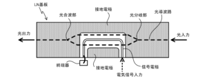
図1は、DP-QPSK変調器などの光変調器の一例を示す平面図であり、光導波路や変調電極を形成したLN基板が筐体内に収容されている。LN基板の入射側には光ファイバにより入力された光波が、入射コリメータ等を介してLN基板の光導波路に導入される。また、LN基板の出射側では、変調された光波が、偏波合成光学系や出射コリメータ等を介して出射側の光ファイバに導入され、光出力として出力される。 FIG. 1 is a plan view showing an example of an optical modulator such as a DP-QPSK modulator, in which an LN substrate on which an optical waveguide and a modulation electrode are formed is housed in a housing. A light wave input through an optical fiber is introduced into the optical waveguide of the LN substrate via an input collimator or the like on the input side of the LN substrate. Further, on the output side of the LN substrate, the modulated light wave is introduced into an optical fiber on the output side via a polarization combining optical system, an output collimator, etc., and is output as optical output.
LN基板の変調電極には、筐体側面に設けたRFコネクタなどを介して導入された電気信号が印加される。LN基板に電気信号を入力する際に、中継基板に形成した電気配線を利用することも可能である。また、LN基板に形成した電極には、DCバイアス電圧を印加するためのDC電極もある。筐体側面に形成したDCリードピンを介して、DCバイアスがLN基板のDC電極に供給される。 An electrical signal introduced via an RF connector provided on the side surface of the housing is applied to the modulation electrode of the LN board. When inputting electrical signals to the LN board, it is also possible to use electrical wiring formed on the relay board. Further, the electrodes formed on the LN substrate include a DC electrode for applying a DC bias voltage. A DC bias is supplied to the DC electrode of the LN substrate through a DC lead pin formed on the side surface of the housing.
図2は、LN基板の一例を示す平面図である。図2では、説明を簡略するため、LN基板上に形成される光導波路では、一つのマッハツェンダー型光導波路を形成・配置している。光導波路の形状はこれに限らず、一つの主マッハツェンダー型光導波路を構成する各分岐導波路に副マッハツェンダー型光導波路を入れ子状に組み込んだ、所謂、ネスト型光導波路も使用される。さらに、図1のDP-QPSK変調器などでは、一つの光導波路を2つに分岐し、分岐した各導波路にネスト型光導波路を接続した光導波路の構成も採用されている。 FIG. 2 is a plan view showing an example of an LN substrate. In FIG. 2, in order to simplify the explanation, one Mach-Zehnder type optical waveguide is formed and arranged in the optical waveguide formed on the LN substrate. The shape of the optical waveguide is not limited to this, and a so-called nested optical waveguide in which a sub Mach-Zehnder optical waveguide is nested in each branch waveguide constituting one main Mach-Zehnder optical waveguide may also be used. Furthermore, in the DP-QPSK modulator shown in FIG. 1, etc., an optical waveguide configuration is also adopted in which one optical waveguide is branched into two, and a nested optical waveguide is connected to each branched waveguide.
図1や図2に示すような光変調器では、外部から光導波路に供給される入射光(光入力)の位置と、外部から変調電極に供給される電気信号によって変調された光波が出射する出射光(光出力)の位置は、基板の長手方向の両端(長方形の基板の短辺部分)に配置されている。図2のLN基板には、光導波路と変調電極が形成されている。変調電極は、信号電極と接地電極とを有し、特に、信号電極は、基板の長手方向に沿った側面側(長方形の基板の長辺部分。図2のLN基板の下辺側)から導入され、同じ側面側又は対向する側面側から導出されている。信号電極の端部には電気信号(変調信号)を終端する終端器が接続されている。 In the optical modulators shown in Figures 1 and 2, a light wave is modulated by the position of incident light (light input) supplied to the optical waveguide from the outside and an electric signal supplied from the outside to the modulation electrode, and then output. The emitted light (light output) is located at both ends of the substrate in the longitudinal direction (short side portions of the rectangular substrate). An optical waveguide and a modulation electrode are formed on the LN substrate in FIG. 2 . The modulation electrode has a signal electrode and a ground electrode. In particular, the signal electrode is introduced from the side surface along the longitudinal direction of the substrate (the long side of the rectangular substrate; the lower side of the LN substrate in FIG. 2). , are derived from the same side or opposite side. A terminator for terminating an electric signal (modulation signal) is connected to the end of the signal electrode.
図2のような基板の長辺部分から信号電極を導入する場合には、特許文献1に示すように、信号電極はマッハツェンダー型光導波路の光分岐部や光合波部を避けて、分岐導波路の直線部分付近や入力導波路等を横切って配置されることが多い。この場合、信号電極が光導波路を横切る際に、Y分岐部等の光分岐部の光の強度比(分岐比)に影響を与えることはない。また同様に、光合波部での合波する光波の強度比(合波比)にも影響を与えることもない。 When a signal electrode is introduced from the long side of the substrate as shown in FIG. It is often placed near the straight part of the wavepath or across the input waveguide. In this case, when the signal electrode crosses the optical waveguide, it does not affect the light intensity ratio (branching ratio) of the optical branching section such as the Y branching section. Similarly, it does not affect the intensity ratio (combining ratio) of the light waves that are combined in the optical multiplexing section.
他方、伝送する電気信号が高速(例えば、50GHz以上)になればなるほど、伝送損失が大きくなるため、所定の位相・タイミングで電気信号を発生することが可能なデジタル信号プロセッサ(Digital Signal Processor,DSP)から信号を増幅し変調器を駆動するためのドライバへ、さらにドライバからLN変調素子(LN基板の信号電極)へと電気信号を伝送する電気信号線路を短くする必要がある。 On the other hand, the faster the electrical signal to be transmitted (for example, 50 GHz or higher), the greater the transmission loss. ) to the driver for amplifying the signal and driving the modulator, and further from the driver to the LN modulation element (signal electrode of the LN substrate), it is necessary to shorten the electric signal line that transmits the electric signal.
伝送損失を少なくするためには、図3に示すように、DSP、ドライバ、光変調素子をほぼ一直線状に配置し、信号線路の長さや曲りを極力少なすることが求められる。また、光変調器の筐体内に、光変調素子であるLN基板だけでなく、ドライバ素子も併せて組み込む、所謂、集積化も行われている。 In order to reduce transmission loss, as shown in FIG. 3, it is required to arrange the DSP, driver, and optical modulation element almost in a straight line, and to minimize the length and bending of the signal line. Also, so-called integration is being carried out, in which not only the LN substrate, which is the light modulation element, but also the driver element is also incorporated into the housing of the optical modulator.
これらを実施する場合、図2に示すような光変調器と異なり、電気信号をLN基板の長手方向に沿った長辺部分からではなく、図4(a)に示すように、LN基板の短辺部分から入力することにより、信号線路を短縮できると共に、信号線路を直線的に配置することが可能となる。 When implementing these, unlike the optical modulator shown in Fig. 2, the electric signal is not transmitted from the long side of the LN substrate along the longitudinal direction, but from the short side of the LN substrate as shown in Fig. 4(a). By inputting from the side portion, the signal line can be shortened and the signal line can be arranged linearly.
特許文献2や図4(a)のようにLN基板の短辺部分(図4(a)のLN基板の右側の短辺)から電気信号を入力する場合には、信号電極は、マッハツェンダー型光導波路などの光分岐部を横切って配置されることが多くなる。このため、信号電極が光導波路を横切る際に、例えば、図4(b)に示すように、Y分岐部等の光分岐部を構成する2つの分岐用導波路の片方に電界が印加され、光の分岐比に影響を与えることとなる。図4(b)は図4(a)の点線A-A’における断面図である。
When inputting an electrical signal from the short side portion of the LN substrate (the right short side of the LN substrate in FIG. 4(a)) as in
また、後述するように光分岐部に接続する入力用導波路の真上に沿って信号電極が配置され、Y分岐部の中央を信号電極が横切る場合であっても、Y分岐部を構成する2つの分岐用導波路の分岐直後付近では、各分岐用導波路に異なる方向の変調電界が印加され、2つの分岐用導波路には異なる屈折率変化が発生する。このため、2つの分岐用導波路に分岐する光波の分岐比が変化する原因となる。 In addition, as will be described later, even if the signal electrode is arranged directly above the input waveguide connected to the optical branch and the signal electrode crosses the center of the Y branch, the signal electrode will not form the Y branch. Immediately after the two branching waveguides branch, modulated electric fields in different directions are applied to each branching waveguide, and different refractive index changes occur in the two branching waveguides. This causes a change in the branching ratio of the light waves branched into the two branching waveguides.
DP-QPSK変調器の場合では、X偏波とY偏波に分岐する初段のY分岐部で分岐比が変動すると、X偏波とY偏波の損失差が変化することとなる。また、ネスト型光導波路のY分岐部の場合では、出力する信号光の消光比が変化することになり、何れの場合でも伝送特性の劣化の原因となる。 In the case of a DP-QPSK modulator, if the branching ratio changes at the first stage Y branching section that branches into X polarization and Y polarization, the loss difference between X polarization and Y polarization will change. Furthermore, in the case of a Y branch of a nested optical waveguide, the extinction ratio of the output signal light changes, which causes deterioration of transmission characteristics in either case.
本発明が解決しようとする課題は、上述したような問題を解決し、光分岐部又は光合波部を信号電極が横切る場合でも、伝送特性の劣化を抑制した光変調器を提供することである。 The problem to be solved by the present invention is to provide an optical modulator that solves the above-mentioned problems and suppresses deterioration of transmission characteristics even when a signal electrode crosses an optical branching section or an optical multiplexing section. .
上記課題を解決するため、本発明の光変調器は、以下の技術的特徴を有する。
(1) 基板に、光導波路と、該光導波路を伝搬する光波を変調する変調電極とを形成し、該基板を筐体内に収容した光変調器において、該光導波路は、1つの光波を2つに分岐する光分岐部又は2つの光波を1つに合波する光合波部を少なくとも備え、該変調電極は、信号電極と接地電極とを有すると共に、該信号電極の一部が該光分岐部又は該光合波部を横切るように配置され、該光分岐部又は該光合波部を横切る該信号電極によって、該光分岐部で分岐する光波の強度比又は該光合波部で合波する光波の強度比が変化することを抑制するための抑制手段を備え、該抑制手段は、該光分岐部又は該光合波部と、該変調電極との間に設けられた樹脂層であり、該樹脂層は、該変調電極が形成する電界が該光導波路に作用する作用部には形成されていないことを特徴とする。
In order to solve the above problems, the optical modulator of the present invention has the following technical features.
(1) In an optical modulator in which an optical waveguide and a modulation electrode for modulating a light wave propagating through the optical waveguide are formed on a substrate, and the substrate is housed in a housing, the optical waveguide modulates one optical wave into two. The modulation electrode includes a signal electrode and a ground electrode, and a part of the signal electrode is connected to the optical branch. The intensity ratio of the light waves branched at the optical branching section or the light waves multiplexed at the optical coupling section is determined by the signal electrode which is arranged to cross the optical branching section or the optical coupling section, and which crosses the optical branching section or the optical coupling section. The suppression means is a resin layer provided between the optical branching section or the optical multiplexing section and the modulation electrode, The layer is characterized in that it is not formed in an action portion where the electric field formed by the modulation electrode acts on the optical waveguide .
(2) 上記(1)に記載の光変調器において、該筐体に設けられ、該変調電極に電気信号を供給するインターフェース部は、該光分岐部又は該光合波部を通過する光波の伝搬方向であり該光分岐部又は該光合波部の線対称軸の延長線と、該筐体の側面とが交差する位置の近傍に形成されていることを特徴とする。 (2) In the optical modulator according to (1) above, the interface section provided in the casing and supplying an electrical signal to the modulation electrode is configured to facilitate propagation of light waves passing through the optical branching section or the optical multiplexing section. It is characterized in that it is formed in the vicinity of a position where an extension line of the line symmetry axis of the optical branching section or the optical multiplexing section intersects with the side surface of the casing.
(3) 上記(1)又は(2)に記載の光変調器において、該光分岐部又は該光合波部はY分岐部で構成され、該Y分岐部は、シングルモードに対応する導波路幅Wを有する1本の入出力用導波路と、該入出力用導波路に接続し、導波路幅が前記Wよりも広い導波路幅で形成される変換用導波路と、該変換用導波路に接続する2つの分岐用導波路を有し、該信号電極が該光分岐部又は該光合波部を横切る位置は、該変換用導波路又は、該変換用導波路から2つの該分岐用導波路の距離が該分岐用導波路を伝搬する光波のモードフィールド径の3倍まで離れるまでの範囲以内の該分岐用導波路の何れかであることを特徴とする。 (3) In the optical modulator according to (1) or (2) above, the optical branching section or the optical multiplexing section is composed of a Y branching section, and the Y branching section has a waveguide width corresponding to a single mode. one input/output waveguide having W; a conversion waveguide connected to the input/output waveguide and having a waveguide width wider than the W; and the conversion waveguide. The position where the signal electrode crosses the optical branching section or the optical multiplexing section is connected to the conversion waveguide or the two branching waveguides connected to the conversion waveguide. The branching waveguide is characterized in that the distance between the waveguides is within a range up to three times the mode field diameter of the light wave propagating through the branching waveguide.
(4) 上記(1)に記載の光変調器において、変調電極と樹脂層とが重なった部分の長さは、変調信号の波長の10分の1以下に設定されていることを特徴とする。 ( 4 ) In the optical modulator according to ( 1 ) above, the length of the overlapping portion of the modulation electrode and the resin layer is set to one-tenth or less of the wavelength of the modulation signal. .
(5) 基板に、光導波路と、該光導波路を伝搬する光波を変調する変調電極とを形成し、該基板を筐体内に収容した光変調器において、該光導波路は、1つの光波を2つに分岐する光分岐部又は2つの光波を1つに合波する光合波部を少なくとも備え、該変調電極は、信号電極と接地電極とを有すると共に、該信号電極の一部が該光分岐部又は該光合波部を横切るように配置され、該光分岐部又は該光合波部を横切る該信号電極によって、該光分岐部で分岐する光波の強度比又は該光合波部で合波する光波の強度比が変化することを抑制するための抑制手段を備え、該抑制手段は、該光分岐部又は該光合波部を通過する光波の伝搬方向であり該光分岐部又は該光合波部の線対称軸に沿って配置され、該線対称軸に対して対称な形状を有し、該信号電極が該光分岐部又は該光合波部を横切る位置では、該信号電極の幅が該分岐用導波路を伝搬する光波のモードフィールド径の3倍以上であることを特徴とする。 ( 5 ) In an optical modulator in which an optical waveguide and a modulation electrode for modulating a light wave propagating through the optical waveguide are formed on a substrate, and the substrate is housed in a housing, the optical waveguide converts one optical wave into two. The modulation electrode includes a signal electrode and a ground electrode, and a part of the signal electrode is connected to the optical branch. The intensity ratio of the light waves branched at the optical branching section or the light waves multiplexed at the optical coupling section is determined by the signal electrode which is arranged to cross the optical branching section or the optical coupling section, and which crosses the optical branching section or the optical coupling section. The suppressing means is provided with a suppressing means for suppressing a change in the intensity ratio of the optical branching section or the optical multiplexing section, and the suppressing means is a propagation direction of the light wave passing through the optical branching section or the optical multiplexing section. The signal electrode is arranged along a line symmetry axis and has a shape symmetrical with respect to the line symmetry axis, and at a position where the signal electrode crosses the optical branching section or the optical multiplexing section, the width of the signal electrode is the same as that of the branching section. It is characterized in that it is three times or more the mode field diameter of the light wave propagating through the waveguide.
本発明は、基板に、光導波路と、該光導波路を伝搬する光波を変調する変調電極とを形成し、該基板を筐体内に収容した光変調器において、該光導波路は、1つの光波を2つに分岐する光分岐部又は2つの光波を1つに合波する光合波部を少なくとも備え、該変調電極は、信号電極と接地電極とを有すると共に、該信号電極の一部が該光分岐部又は該光合波部を横切るように配置され、該光分岐部又は該光合波部を横切る該信号電極によって、該光分岐部で分岐する光波の強度比又は該光合波部で合波する光波の強度比が変化することを抑制するための抑制手段を備えているため、伝送特性の劣化を抑制した光変調器を提供することが可能となる。 The present invention provides an optical modulator in which an optical waveguide and a modulation electrode for modulating a light wave propagating through the optical waveguide are formed on a substrate, and the substrate is housed in a housing, in which the optical waveguide modulates one optical wave. The modulation electrode includes at least an optical branching section that branches into two or an optical multiplexing section that multiplexes two light waves into one, and the modulation electrode has a signal electrode and a ground electrode, and a part of the signal electrode The signal electrode, which is arranged to cross the branching part or the optical multiplexing part, and which crosses the optical branching part or the optical multiplexing part, determines the intensity ratio of the light waves branched at the optical branching part or the intensity ratio of the light waves that are combined at the optical multiplexing part. Since the suppressing means for suppressing changes in the intensity ratio of light waves is provided, it is possible to provide an optical modulator that suppresses deterioration of transmission characteristics.
以下、本発明の光変調器について、好適例を用いて詳細に説明する。
本発明の光変調器は、図6、7、9、11又は12に示すような、光導波路の光分岐部又は光合波部を信号電極が横切るよう構成された光変調器を対象としている。
具体的には、図6などに示すように、基板に、光導波路と、該光導波路を伝搬する光波を変調する変調電極とを形成し、図8又は10に示すように、該基板を筐体内に収容した光変調器において、該光導波路は、1つの光波を2つに分岐する光分岐部又は2つの光波を1つに合波する光合波部を少なくとも備え、該変調電極は、信号電極と接地電極とを有すると共に、該信号電極の一部が該光分岐部又は該光合波部を横切るように配置され、該光分岐部又は該光合波部を横切る該信号電極によって、該光分岐部で分岐する光波の強度比又は該光合波部で合波する光波の強度比が変化することを抑制するための抑制手段を備えたことを特徴とする。
Hereinafter, the optical modulator of the present invention will be explained in detail using a preferred example.
The optical modulator of the present invention is directed to an optical modulator configured such that a signal electrode crosses an optical branching section or an optical multiplexing section of an optical waveguide, as shown in FIG. 6, 7, 9, 11 or 12.
Specifically, as shown in FIG. 6 etc., an optical waveguide and a modulation electrode for modulating the light waves propagating through the optical waveguide are formed on a substrate, and the substrate is placed in a casing as shown in FIG. 8 or 10. In the optical modulator housed in the body, the optical waveguide includes at least an optical branching section that branches one optical wave into two or an optical multiplexing section that multiplexes two optical waves into one, and the modulating electrode has a signal It has an electrode and a ground electrode, and a part of the signal electrode is arranged to cross the optical branching section or the optical multiplexing section, and the signal electrode that crosses the optical branching section or the optical multiplexing section allows the light to be The present invention is characterized by comprising a suppressing means for suppressing changes in the intensity ratio of light waves branched at the branching section or the intensity ratio of light waves coupled at the optical multiplexing section.
本発明の光変調器に使用される基板としては、ニオブ酸リチウム(LN)などの電気光学効果を有する基板や、半導体基板などが利用可能である。光導波路については、例えば、LN結晶成長やLN基板加工により導波路を形成したり、LN基板にTiなどの金属を熱拡散して光導波路を形成するなどの公知の技術を利用することが可能である。また、電極については、例えば、金メッキ処理で電極を形成するなどの公知の技術を利用することが可能である。本発明の説明では、光導波路や電極が形成された基板(チップ)を「光変調素子」という場合もある。 As the substrate used in the optical modulator of the present invention, a substrate having an electro-optic effect such as lithium niobate (LN), a semiconductor substrate, etc. can be used. For the optical waveguide, it is possible to use known techniques such as forming a waveguide by LN crystal growth or LN substrate processing, or forming an optical waveguide by thermally diffusing a metal such as Ti onto an LN substrate. It is. Further, for the electrodes, it is possible to use a known technique such as forming the electrodes by gold plating, for example. In the description of the present invention, a substrate (chip) on which an optical waveguide and electrodes are formed is sometimes referred to as a "light modulation element."
本発明の光変調器において、図3、8又は10に示すように、筐体内に配置される光変調素子の変調電極に電気信号を供給するため、該筐体に設けられるインターフェース部(図8又は10のRF/DCコネクタの特にRFコネクタ)は、光分岐部又は光合波部を通過する光波の伝搬方向(各図面の左右方向)であり該光分岐部又は該光合波部の線対称軸の延長線と、該筐体の側面とが交差する位置の近傍に形成されている。この結果、インターフェース部の外側近傍にDSPを配置し、筐体内のインタフェース部の内側近傍にドライバ素子を配置し、さらに、ドライバ素子のインターフェース部と反対側には、光変調素子を配置することができる。そして、DSPから光変調素子(変調電極)までを、より短い配線でほぼ直線状に接続することができ、電気信号の伝送損失を最小限に抑制することが可能となる。 In the optical modulator of the present invention, as shown in FIG. 3, 8 or 10, an interface section (FIG. 8 or 10 RF/DC connectors, especially the RF connector) is the propagation direction of the light wave passing through the optical branching section or the optical multiplexing section (the left-right direction in each drawing), and the line symmetry axis of the optical branching section or the optical multiplexing section. It is formed near the position where the extension line intersects with the side surface of the housing. As a result, it is possible to arrange the DSP near the outside of the interface section, the driver element near the inside of the interface section within the housing, and the light modulation element on the opposite side of the driver element from the interface section. can. Furthermore, it is possible to connect the DSP to the optical modulation element (modulation electrode) almost linearly with shorter wiring, and it is possible to suppress transmission loss of electric signals to a minimum.
図8又は10では、インターフェース部であるRF/DCコネクタが筐体の短辺側に配置され、反対の短辺側には、光入力/光出力部が配置されている。光入力部は、筐体の長辺側(図面の下側の長辺側)に配置することも可能である。図8の場合は、光変調素子自体への光入力部分を基板の長辺側に配置し、筐体の光入力部から導入された光波は、空間光学系を介して光変調素子を構成する基板の光導波路に入射される。また、図10のように、光入力部と光出力部とを同じ基板の短辺側に配置し、後述する図11又は12のように、光入力部から光変調部(変調信号により光波が変調作用を受ける光導波路の部分)までの折り返し光路を基板内に形成した光導波路で構成することも可能である。 In FIG. 8 or 10, the RF/DC connector, which is an interface section, is arranged on the short side of the housing, and the optical input/output section is arranged on the opposite short side. The optical input section can also be arranged on the long side of the housing (lower long side in the drawing). In the case of FIG. 8, the light input part to the light modulation element itself is placed on the long side of the substrate, and the light wave introduced from the light input part of the casing forms the light modulation element via the spatial optical system. The light is incident on the optical waveguide of the substrate. In addition, as shown in FIG. 10, the optical input section and the optical output section are arranged on the short side of the same substrate, and as shown in FIG. It is also possible to construct the folded optical path to the part of the optical waveguide that receives the modulation effect by an optical waveguide formed in the substrate.
基板内の光変調部では、図8又は10の右から左方向に光波が伝搬し、光変調作用を受けた後、基板端部から出射すると共に、偏波合成部を含む空間光学系で偏波合成され、光出力部から出射する。電気信号も基板内の変調電極(信号電極)を図8又は10の右から左に伝播する。筐体内のインターフェース部近傍には、ドライバ素子を含む中継基板が配置され、インターフェース部から中継基板、中継基板から光変調素子(基板)へと最短経路で変調信号が伝送されている。 In the light modulation section in the substrate, the light wave propagates from right to left in FIG. 8 or 10, and after receiving the light modulation effect, is emitted from the end of the substrate and is polarized by the spatial optical system including the polarization combining section. The waves are combined and emitted from the light output section. Electrical signals also propagate through modulation electrodes (signal electrodes) in the substrate from right to left in FIG. 8 or 10. A relay board including a driver element is arranged near the interface section in the housing, and a modulated signal is transmitted from the interface section to the relay board and from the relay board to the optical modulation element (substrate) through the shortest route.
電気信号を伝搬する信号電極における伝送損失を抑制するためには、図4に示すように、信号電極の入力端子から光導波路と変調電極との相互作用部までがほぼ直線形状をしていることが必要となる。この結果、光導波路の光分岐部を信号電極が横切ることとなる。 In order to suppress the transmission loss in the signal electrode that propagates the electric signal, as shown in Figure 4, the area from the input terminal of the signal electrode to the interaction part between the optical waveguide and the modulation electrode must have an almost straight line shape. Is required. As a result, the signal electrode crosses the optical branch portion of the optical waveguide.
図5は、Y分岐部を利用した光分岐部の一例を示す拡大図であり、点線C1から右側の入力用導波路、点線C1からC2までの区間にある変換用導波路、点線C2から左側の分岐用導波路で光分岐部を構成している。光合波部の構成もY分岐部を採用することが可能であり、その際には、2つの分岐用導波路が変換用導波路に接続し、変換用導波路を介して、1つの出力用導波路に繋がっている。例えば、図5のY分岐部の光伝搬方向を逆方向(図の左から右に向かう方向)にした形状となる。以下では、光分岐部を中心に説明を行うが、光合波部の一部を信号電極が横切る場合にも、本発明を適用することで、合波する光波の強度比の変化を抑制することが可能となる。なお、図5ではY分岐部について示したが、他の光合分岐手段であるMMI(多モード干渉用導波路)やカプラー等にも、本発明は適用可能である。 FIG. 5 is an enlarged view showing an example of an optical branching section using a Y branching section, with an input waveguide on the right side from dotted line C1, a conversion waveguide on the section from dotted line C1 to C2, and a left side from dotted line C2. The optical branching section is composed of branching waveguides. It is also possible to adopt a Y-branching configuration for the optical multiplexing section, in which case two branching waveguides are connected to a conversion waveguide, and one output waveguide is connected to the conversion waveguide via the conversion waveguide. connected to a waveguide. For example, the shape is such that the light propagation direction of the Y branch in FIG. 5 is reversed (from left to right in the figure). The following description will focus on the optical branching section, but the present invention can also be applied to cases where a signal electrode crosses a part of the optical multiplexing section to suppress changes in the intensity ratio of the optical waves to be multiplexed. becomes possible. Although FIG. 5 shows a Y-branching section, the present invention is also applicable to other optical coupling/branching means such as MMI (multimode interference waveguide) and couplers.
光分岐部は、シングルモードに対応する導波路幅Wを有する入力用導波路と、該入力用導波路に接続し、導波路幅が前記Wと同じとなる一方の端部から、前記Wよりも広い導波路幅を有する他方の端部との間に形成される変換用導波路と、該変換用導波路に接続する2つの分岐用導波路から構成されている。本発明では、信号電極が光分岐部を横切る位置が、変換用導波路又は、変換用導波路から2つの分岐用導波路の距離Dが分岐用導波路を伝搬する光波のモードフィールド径の3倍まで離れるまでの範囲以内の該分岐用導波路の何れかの場合には、光分岐部の光波の分岐比が、所望の設定値、例えば、1対1から変化することを見出して、本発明の光変調器を完成させている。 The optical branching section includes an input waveguide having a waveguide width W corresponding to a single mode, and an input waveguide connected to the input waveguide, from one end where the waveguide width is the same as the W, and from the W to the input waveguide. The conversion waveguide is formed between the converting waveguide and the other end having a wider waveguide width, and the two branching waveguides are connected to the converting waveguide. In the present invention, the position where the signal electrode crosses the optical branching section is the conversion waveguide or the distance D from the conversion waveguide to the two branching waveguides is 3 times the mode field diameter of the light wave propagating through the branching waveguide. In the case of any of the branching waveguides within a range of up to twice as far apart, the branching ratio of the light wave at the optical branching section changes from the desired setting value, for example, 1:1, and the present invention The optical modulator of the invention has been completed.
図5に示す、点線C1から点線C3の範囲(距離Dは分岐用導波路を伝搬する光波のシングルモードのモードフィールド径の3倍)以内を信号電極が光導波路を横切る場合には、光分岐部の光波の分岐比が設定値(例えば、1対1)から変化し易い。なお、本発明において、「信号電極が光分岐部又は光合波部を横切る」ことの意味は、図5に示すY分岐部の点線C1から点線C3の範囲内に信号電極が配置されることを意味している。 If the signal electrode crosses the optical waveguide within the range from dotted line C1 to dotted line C3 (distance D is three times the mode field diameter of the single mode of the light wave propagating through the branching waveguide) shown in FIG. The branching ratio of the light waves in the section easily changes from the set value (for example, 1:1). In the present invention, "the signal electrode crosses the optical branching section or the optical multiplexing section" means that the signal electrode is arranged within the range from the dotted line C1 to the dotted line C3 of the Y-branching section shown in FIG. It means.
分岐比の変化を抑制するためには、図6に示すように、光分岐部を構成する光導波路と変調電極(信号電極と接地電極(GND))との間に、抑制手段として樹脂層を設けている。樹脂層としては、熱可塑性樹脂又は熱硬化性樹脂等の樹脂であり、一例として、ポリアミド系樹脂、メラミン系樹脂、フェノール系樹脂、アミノ系樹脂、エポキシ系樹脂等がある。また、樹脂層は、例えば永久レジストを用いることができ、熱硬化型の樹脂を材料とするフォトレジスト材料が利用可能である。光変調素子の製造工程において、スピンコートにより基板上に樹脂層を塗布し、通常のフォトリソグラフィプロセスによってパターニングを行った後に熱硬化させることで、変調電極と基板との間に樹脂層を配置することができる。さらに、樹脂層の屈折率は、光導波路のコア部の光屈折率より低くなるよう選択する必要がある。 In order to suppress changes in the branching ratio, as shown in FIG. It is set up. The resin layer is a resin such as a thermoplastic resin or a thermosetting resin, and examples include polyamide resin, melamine resin, phenol resin, amino resin, and epoxy resin. Furthermore, for the resin layer, a permanent resist can be used, for example, and a photoresist material made of a thermosetting resin can be used. In the manufacturing process of light modulation elements, a resin layer is applied onto the substrate by spin coating, patterned by a normal photolithography process, and then thermally cured to place the resin layer between the modulation electrode and the substrate. be able to. Furthermore, the refractive index of the resin layer needs to be selected to be lower than the optical refractive index of the core portion of the optical waveguide.
また、永久レジストを利用することにより、容易にパターニング可能であること、厚さ3~5μmと厚く成膜できることなどの利点がある。本発明の構成において基板表面にバッファ層(SiO2膜)を入れても良いが、バッファ層は厚さ1μm程度と薄く、本発明のような効果を得ることはできない。 Further, by using a permanent resist, there are advantages such as easy patterning and the ability to form a film as thick as 3 to 5 μm. In the structure of the present invention, a buffer layer (SiO 2 film) may be provided on the surface of the substrate, but the buffer layer is as thin as about 1 μm, and the effect as achieved by the present invention cannot be obtained.
図6(b)は、図6(a)の点線A-A’における断面図を示したものである。図6(b)に示すように、抑制手段としての樹脂層を配置することで、信号電極と接地電極との間に形成される電界が、一方の分岐用導波路(図6(b)の右側の光導波路)に印加されるのを抑制している。これにより、光分岐部を構成する分岐用導波路に、余分な電界が印加されず、分岐する光波の分岐比が変化することが抑えられる。なお、樹脂層は、信号電極、又は信号電極と接地電極が光導波路を横切る場所に局所的に設けても良いし、変調電極やDC電極などの電極が形成する電界と光導波路とが相互作用する作用部を除き、基板表面に広く形成することも可能である。 FIG. 6(b) shows a cross-sectional view taken along the dotted line A-A' in FIG. 6(a). As shown in FIG. 6(b), by arranging the resin layer as a suppressing means, the electric field formed between the signal electrode and the ground electrode is (optical waveguide on the right). As a result, no extra electric field is applied to the branching waveguide constituting the optical branching section, and changes in the branching ratio of the light waves to be branched can be suppressed. Note that the resin layer may be provided locally at a location where the signal electrode or the signal electrode and the ground electrode cross the optical waveguide, or where the electric field formed by the modulation electrode, DC electrode, etc. interacts with the optical waveguide. It is also possible to form a wide area on the surface of the substrate, except for the active part.
図6のように、信号電極を含む変調電極の伝送路の途中に樹脂層を配置する場合には、樹脂層が存在する部分と樹脂層が存在しない部分とでは、変調電極の特性インピーダンスが変化する。変調電極と樹脂層とが重なった部分の長さが、変調信号の波長の10分の1以下であれば、特性インピーダンスの変化の影響は極めて少ないが、それよりも長くなる場合には、特性インピーダンスの変化を抑制する工夫が必要となる。具体的には、樹脂層上の信号電極の幅を、他の部分と比較して、広くしたり、樹脂層上の信号電極と接地電極とのギャップ幅を、他の部分と比較して、狭くすることが考えられる。また、信号電極の幅やキャップ幅を変化させる場合には、変化する部分をテーパー形状で連続的に調整してもよい。 As shown in Figure 6, when a resin layer is placed in the middle of the transmission path of the modulation electrode including the signal electrode, the characteristic impedance of the modulation electrode changes between the part where the resin layer is present and the part where the resin layer is not present. do. If the length of the overlap between the modulation electrode and the resin layer is one-tenth or less of the wavelength of the modulation signal, the effect of changes in characteristic impedance is extremely small; however, if it is longer than that, the characteristics It is necessary to devise ways to suppress changes in impedance. Specifically, the width of the signal electrode on the resin layer is made wider compared to other parts, and the gap width between the signal electrode and the ground electrode on the resin layer is made wider compared to other parts. It is possible to narrow it down. Further, when changing the width of the signal electrode or the cap width, the changing portion may be continuously adjusted in a tapered shape.
図7は、図6のマッハツェンダー型光導波路の入力用導波路に重なるように信号電極を配置した場合を示している。また、図7(b)は図7(a)の点線A-A’における断面図を示しており、特に、図7(b)は、光分岐部を構成する分岐用導波路が分岐した直後の様子を示している。このような分岐用導波路が近接して配置されている状況であっても、抑制手段としての樹脂層を配置することにより、2つの分岐用導波路の各々に異なる電界(異なる方向の電界が作用する場合を含む)が作用することが抑制され、2つの分岐用導波路において異なる屈折率変化が発生することが防止される。その結果、2つの分岐用導波路に分岐する光波の分岐比が変化することが抑制される。 FIG. 7 shows a case where signal electrodes are arranged so as to overlap the input waveguide of the Mach-Zehnder type optical waveguide shown in FIG. In addition, FIG. 7(b) shows a cross-sectional view taken along the dotted line AA′ in FIG. 7(a), and in particular, FIG. It shows the situation. Even in such a situation where the branching waveguides are arranged close to each other, by arranging the resin layer as a suppressing means, different electric fields (electric fields in different directions) can be generated in each of the two branching waveguides. (including the case where the branching waveguide acts) is suppressed, and different refractive index changes are prevented from occurring in the two branching waveguides. As a result, changes in the branching ratio of the light waves branched into the two branching waveguides are suppressed.
図9は、本発明の光変調器に使用可能な光変調素子の他の例である。なお、図9の基板に形成される光導波路の入力部は、基板の長辺側に設けられており、図8のように、基板の長辺側に光波の入力部を備える光変調器には、好適に用いることが可能である。 FIG. 9 shows another example of a light modulation element that can be used in the light modulator of the present invention. Note that the input section of the optical waveguide formed on the substrate in FIG. 9 is provided on the long side of the substrate, and as shown in FIG. can be suitably used.
図9の光変調素子の主な特徴は、光分岐部に重なるように配置した信号電極の形状である。図9は、光分岐部を通過する光波の伝搬方向であり該光分岐部の線対称軸Eに沿って配置され、該線対称軸Eに対して対称な形状を有する信号電極を用いた例を示している。上述した線対称軸に対して対称な形状を信号電極が有しているため、光分岐部における分岐比に与える影響も、線対称軸を挟んでほぼ同じとなるため、分岐比が例えば1対1から変化することが抑制される。なお、図9では、中継基板にドライバ素子(DRV)が配置された様子を図示している。 The main feature of the light modulation element shown in FIG. 9 is the shape of the signal electrode arranged so as to overlap the light branching section. FIG. 9 shows the propagation direction of the light wave passing through the optical branching section, which is an example using a signal electrode arranged along the line symmetry axis E of the optical branching section and having a shape symmetrical with respect to the line symmetry axis E. It shows. Since the signal electrode has a shape that is symmetrical with respect to the above-mentioned line symmetry axis, the influence on the branching ratio at the optical branching section is almost the same across the line symmetry axis. Changes from 1 are suppressed. Note that FIG. 9 shows a driver element (DRV) arranged on a relay board.
図9では、信号電極の幅が変化しており、入力用導波路上よりも光導波路との作用部の方が狭くなるよう設定されている。信号電極の形状として、特に重要なことは、信号電極が光分岐部を横切る位置では、信号電極の幅が、図5に示す、分岐用導波路を伝搬する光波のモードフィールド径の3倍(符号D)以上であることである。このように幅の広い信号電極を用いて光分岐部(Y分岐部)を横切ることで、導波路に印加される電界が分散されるため、分岐比等の変化を抑制する抑制手段として機能することが可能となる。 In FIG. 9, the width of the signal electrode is changed, and is set so that the area where it interacts with the optical waveguide is narrower than the area where it interacts with the input waveguide. What is particularly important about the shape of the signal electrode is that at the position where the signal electrode crosses the optical branch, the width of the signal electrode should be three times the mode field diameter of the light wave propagating through the branching waveguide, as shown in Figure 5. Code D) or higher. In this way, by using a wide signal electrode to cross the optical branching section (Y branching section), the electric field applied to the waveguide is dispersed, so it functions as a suppressing means to suppress changes in the branching ratio, etc. becomes possible.
また、信号電極を途中で2つに分け、その後合流するように構成し、2つに分かれた部分で光分岐部(Y分岐部)の変換用導波路等を迂回するように信号電極を配置することも可能である。当然、光分岐部を横切る分岐した信号電極の間隔は、図5の符号Dよりも広いことが好ましい。 In addition, the signal electrode is divided into two parts in the middle and then merged, and the signal electrode is arranged so that the two parts bypass the conversion waveguide of the optical branch (Y branch part). It is also possible to do so. Naturally, it is preferable that the interval between the branched signal electrodes crossing the optical branching section be wider than the distance D shown in FIG.
図9のような信号電極を用いる場合であっても、光導波路と変調電極とが重なった場所には、図6又は7に示すような樹脂層を配置することが可能である。これにより、さらに、光分岐部の分岐比に与える影響を抑制することが可能となる。 Even when using a signal electrode as shown in FIG. 9, it is possible to arrange a resin layer as shown in FIG. 6 or 7 where the optical waveguide and modulation electrode overlap. This makes it possible to further suppress the influence on the branching ratio of the optical branching section.
図7又は図9では、マッハツェンダー型光導波路の特に入力用光導波路及びそれに続く分岐用導波路の一部に対して、信号電極や接地電極を対称に配置している。このように、光導波路に対して信号電極等の電極(DCバイアス電極を含む)を対称に配置することで、光導波路に加わる内部応力が均一化又は対称化し、光変調素子の温度変動によるDCドリフトの発生を抑制することが可能となる。 In FIG. 7 or 9, signal electrodes and ground electrodes are arranged symmetrically with respect to a part of the Mach-Zehnder optical waveguide, particularly the input optical waveguide and the branching waveguide following it. In this way, by arranging electrodes such as signal electrodes (including DC bias electrodes) symmetrically with respect to the optical waveguide, the internal stress applied to the optical waveguide becomes uniform or symmetrical, and the DC It becomes possible to suppress the occurrence of drift.
図10に示すように、光変調素子を構成する基板の一方の短辺側から光波を入出力する場合について、さらに詳細に説明する。図11及び12は、図10の光変調素子の具体例であり、光導波路として4つのマッハツェンダー型光導波路を並列に配置した、2つのネスト型光導波路を用いている。また、各ネスト型光導波路で変調された光波は、基板外の偏波合成部を介して偏波合成して出力される。 As shown in FIG. 10, the case where light waves are input and output from one short side of the substrate constituting the light modulation element will be described in more detail. 11 and 12 are specific examples of the optical modulation element shown in FIG. 10, in which two nested optical waveguides in which four Mach-Zehnder optical waveguides are arranged in parallel are used as optical waveguides. Further, the light waves modulated by each nested optical waveguide are polarized and combined via a polarization combiner outside the substrate and output.
図11及び12では、基板の同じ短辺側に光波の入出部を配置するため、基板内に入力した光波を折り返すための光導波路が形成されている。また、図11及び12では、基板の他の短辺側から複数の電気信号(変調信号)が入力されている。また、信号電極の終端部には、終端抵抗などを含む終端器が接続され、電気信号の反射が抑制されている。終端器は、基板の2つの長辺側に分かれて配置されているが、一方の長辺側に集約することも可能である。さらに、フリップチップボンディング等を利用して基板上に配置することも可能である。 In FIGS. 11 and 12, in order to arrange the light wave input and output parts on the same short side of the substrate, an optical waveguide is formed for folding back the light wave input into the substrate. Furthermore, in FIGS. 11 and 12, a plurality of electrical signals (modulation signals) are input from the other short side of the substrate. Furthermore, a terminator including a terminating resistor is connected to the terminal end of the signal electrode to suppress reflection of the electric signal. Although the terminators are arranged separately on the two long sides of the board, it is also possible to put them together on one of the long sides. Furthermore, it is also possible to arrange it on a substrate using flip chip bonding or the like.
図11の光変調素子では、図6と同様に、4つのマッハツェンダー型光導波路に対し、光分岐部の入力用導波路と信号電極(RF信号電極)とが重なるのを避けながら、光分岐部を信号電極が横切る場合を示している。また、図12の光変調素子では、図7と同様に、4つのマッハツェンダー型光導波路に対し、光分岐部の入力用導波路と信号電極(RF信号電極)とが重なるように配置しながら、光分岐部を信号電極が横切る場合を示している。図11及び12においても、光分岐部を信号電極(RF信号電極)が横切る位置に樹脂層を配置し、分岐比が変化することを抑制している。なお、光導波路をRF信号電極やDC信号電極が横切る他の位置においても、樹脂層を配置し、不要場所で信号電極の電界が光導波路に印加されることや、光導波路を伝搬する光波が信号電極に吸収されることを抑制することも可能である。 In the optical modulation element of FIG. 11, as in FIG. 6, optical branching is performed for the four Mach-Zehnder optical waveguides while avoiding overlapping of the input waveguide and the signal electrode (RF signal electrode) of the optical branching section. The case where the signal electrode crosses the area is shown. In addition, in the optical modulation element of FIG. 12, similarly to FIG. 7, the input waveguide and the signal electrode (RF signal electrode) of the optical branching section are arranged so as to overlap with respect to the four Mach-Zehnder type optical waveguides. , shows the case where the signal electrode crosses the optical branch. In FIGS. 11 and 12 as well, a resin layer is placed at a position where a signal electrode (RF signal electrode) crosses the optical branching portion to suppress changes in the branching ratio. Note that a resin layer is placed at other positions where the RF signal electrode and DC signal electrode cross the optical waveguide to prevent the electric field of the signal electrode from being applied to the optical waveguide at unnecessary locations and to prevent light waves propagating through the optical waveguide from being applied to the optical waveguide. It is also possible to suppress absorption by the signal electrode.
以上説明したように、本発明によれば、光分岐部又は光合波部を信号電極が横切る場合でも、伝送特性の劣化を抑制した光変調器を提供することが可能となる。 As described above, according to the present invention, it is possible to provide an optical modulator that suppresses deterioration of transmission characteristics even when a signal electrode crosses an optical branching section or an optical multiplexing section.
Claims (5)
該光導波路は、1つの光波を2つに分岐する光分岐部又は2つの光波を1つに合波する光合波部を少なくとも備え、
該変調電極は、信号電極と接地電極とを有すると共に、該信号電極の一部が該光分岐部又は該光合波部を横切るように配置され、
該光分岐部又は該光合波部を横切る該信号電極によって、該光分岐部で分岐する光波の強度比又は該光合波部で合波する光波の強度比が変化することを抑制するための抑制手段を備え、
該抑制手段は、該光分岐部又は該光合波部と、該変調電極との間に設けられた樹脂層であり、該樹脂層は、該変調電極が形成する電界が該光導波路に作用する作用部には形成されていないことを特徴とする光変調器。 An optical modulator in which an optical waveguide and a modulation electrode for modulating a light wave propagating through the optical waveguide are formed on a substrate, and the substrate is housed in a housing,
The optical waveguide includes at least an optical branching section that branches one optical wave into two, or an optical multiplexing section that multiplexes two optical waves into one,
The modulation electrode has a signal electrode and a ground electrode, and is arranged such that a part of the signal electrode crosses the optical branching section or the optical multiplexing section,
Suppression for suppressing changes in the intensity ratio of light waves branched at the optical branching section or the intensity ratio of light waves combined at the optical combining section due to the signal electrode crossing the optical branching section or the optical multiplexing section. have the means ,
The suppressing means is a resin layer provided between the optical branching section or the optical multiplexing section and the modulation electrode, and the resin layer allows the electric field formed by the modulation electrode to act on the optical waveguide. An optical modulator characterized in that it is not formed in an action part .
該Y分岐部は、シングルモードに対応する導波路幅Wを有する1本の入出力用導波路と、該入出力用導波路に接続し、導波路幅が前記Wよりも広い導波路幅で形成される変換用導波路と、該変換用導波路に接続する2つの分岐用導波路を有し、
該信号電極が該光分岐部又は該光合波部を横切る位置は、該変換用導波路又は、該変換用導波路から2つの該分岐用導波路の距離が該分岐用導波路を伝搬する光波のモードフィールド径の3倍まで離れるまでの範囲以内の該分岐用導波路の何れかであることを特徴とする光変調器。 The optical modulator according to claim 1 or 2, wherein the optical branching section or the optical multiplexing section is composed of a Y branching section,
The Y branch part includes one input/output waveguide having a waveguide width W corresponding to a single mode, and a waveguide connected to the input/output waveguide, the waveguide width being wider than the waveguide width W. It has a conversion waveguide formed and two branch waveguides connected to the conversion waveguide,
The position where the signal electrode crosses the optical branching section or the optical multiplexing section is determined by the conversion waveguide or the distance between the two branching waveguides from the conversion waveguide to the optical wave propagating through the branching waveguide. An optical modulator characterized in that the branching waveguide is within a range up to three times the mode field diameter of the branching waveguide.
該光導波路は、1つの光波を2つに分岐する光分岐部又は2つの光波を1つに合波する光合波部を少なくとも備え、
該変調電極は、信号電極と接地電極とを有すると共に、該信号電極の一部が該光分岐部又は該光合波部を横切るように配置され、
該光分岐部又は該光合波部を横切る該信号電極によって、該光分岐部で分岐する光波の強度比又は該光合波部で合波する光波の強度比が変化することを抑制するための抑制手段を備え、
該抑制手段は、該光分岐部又は該光合波部を通過する光波の伝搬方向であり該光分岐部又は該光合波部の線対称軸に沿って配置され、該線対称軸に対して対称な形状を有し、該信号電極が該光分岐部又は該光合波部を横切る位置では、該信号電極の幅が該分岐用導波路を伝搬する光波のモードフィールド径の3倍以上であることを特徴とする光変調器。 An optical modulator in which an optical waveguide and a modulation electrode for modulating a light wave propagating through the optical waveguide are formed on a substrate, and the substrate is housed in a housing,
The optical waveguide includes at least an optical branching section that branches one optical wave into two, or an optical multiplexing section that multiplexes two optical waves into one,
The modulation electrode has a signal electrode and a ground electrode, and is arranged such that a part of the signal electrode crosses the optical branching section or the optical multiplexing section,
Suppression for suppressing changes in the intensity ratio of light waves branched at the optical branching section or the intensity ratio of light waves combined at the optical combining section due to the signal electrode crossing the optical branching section or the optical multiplexing section. have the means,
The suppressing means is disposed along the axis of line symmetry of the optical branching unit or the optical multiplexing unit, which is the propagation direction of the light wave passing through the optical branching unit or the optical multiplexing unit, and is symmetrical with respect to the axis of line symmetry. The width of the signal electrode is at least three times the mode field diameter of the light wave propagating through the branching waveguide at the position where the signal electrode crosses the optical branching section or the optical multiplexing section. An optical modulator featuring:
Priority Applications (4)
| Application Number | Priority Date | Filing Date | Title |
|---|---|---|---|
| JP2020062097A JP7347300B2 (en) | 2020-03-31 | 2020-03-31 | light modulator |
| CN202110076101.7A CN113534507B (en) | 2020-03-31 | 2021-01-20 | optical modulator |
| CN202120156854.4U CN215375995U (en) | 2020-03-31 | 2021-01-20 | light modulator |
| US17/170,034 US11493788B2 (en) | 2020-03-31 | 2021-02-08 | Optical modulator |
Applications Claiming Priority (1)
| Application Number | Priority Date | Filing Date | Title |
|---|---|---|---|
| JP2020062097A JP7347300B2 (en) | 2020-03-31 | 2020-03-31 | light modulator |
Publications (2)
| Publication Number | Publication Date |
|---|---|
| JP2021162640A JP2021162640A (en) | 2021-10-11 |
| JP7347300B2 true JP7347300B2 (en) | 2023-09-20 |
Family
ID=77857450
Family Applications (1)
| Application Number | Title | Priority Date | Filing Date |
|---|---|---|---|
| JP2020062097A Active JP7347300B2 (en) | 2020-03-31 | 2020-03-31 | light modulator |
Country Status (3)
| Country | Link |
|---|---|
| US (1) | US11493788B2 (en) |
| JP (1) | JP7347300B2 (en) |
| CN (2) | CN113534507B (en) |
Families Citing this family (2)
| Publication number | Priority date | Publication date | Assignee | Title |
|---|---|---|---|---|
| JP7347300B2 (en) * | 2020-03-31 | 2023-09-20 | 住友大阪セメント株式会社 | light modulator |
| WO2023117191A1 (en) * | 2021-12-24 | 2023-06-29 | Elstar Dynamics Patents B.V. | Substrate comprising electrodes and light modulator with reduced diffraction |
Citations (8)
| Publication number | Priority date | Publication date | Assignee | Title |
|---|---|---|---|---|
| US20020061155A1 (en) | 2000-11-17 | 2002-05-23 | Jian-Jun He | Digital optical switch |
| JP2003202533A (en) | 2001-12-28 | 2003-07-18 | Ricoh Co Ltd | Organic waveguide type optical modulator and method of manufacturing organic waveguide type optical modulator |
| JP2012078376A (en) | 2010-09-30 | 2012-04-19 | Sumitomo Osaka Cement Co Ltd | Optical control element |
| JP2014235218A (en) | 2013-05-31 | 2014-12-15 | 富士通オプティカルコンポーネンツ株式会社 | Optical modulator |
| JP2018028623A (en) | 2016-08-18 | 2018-02-22 | 住友電気工業株式会社 | Optical semiconductor device and method for manufacturing optical semiconductor device |
| CN109164602A (en) | 2018-09-29 | 2019-01-08 | 深圳市芯思杰智慧传感技术有限公司 | A kind of optical waveguide phase-modulator chip with improvement structure |
| JP2019174750A (en) | 2018-03-29 | 2019-10-10 | 住友大阪セメント株式会社 | Optical device and method for manufacturing the same |
| JP2020016717A (en) | 2018-07-24 | 2020-01-30 | 住友大阪セメント株式会社 | Optical waveguide element |
Family Cites Families (10)
| Publication number | Priority date | Publication date | Assignee | Title |
|---|---|---|---|---|
| JP4911529B2 (en) * | 2005-02-22 | 2012-04-04 | 日本碍子株式会社 | Light modulator |
| US7400787B2 (en) * | 2005-04-07 | 2008-07-15 | Photonic Systems, Inc. | Optical modulator with coupled coplanar strip electrode and domain inversion |
| JP2007025371A (en) * | 2005-07-19 | 2007-02-01 | Ricoh Co Ltd | Organic waveguide type optical modulator and optical communication system |
| JP2008039859A (en) * | 2006-08-01 | 2008-02-21 | Fujitsu Ltd | Light modulator |
| JP5012624B2 (en) * | 2008-03-31 | 2012-08-29 | 住友大阪セメント株式会社 | Optical waveguide device |
| JP5983256B2 (en) * | 2012-09-28 | 2016-08-31 | 住友大阪セメント株式会社 | Light modulator |
| JP6287084B2 (en) | 2012-11-09 | 2018-03-07 | 住友電気工業株式会社 | Optical integrated device, optical module |
| JP6056800B2 (en) * | 2014-03-31 | 2017-01-11 | 住友大阪セメント株式会社 | Light modulator |
| JP6107869B2 (en) | 2015-03-31 | 2017-04-05 | 住友大阪セメント株式会社 | Light modulator |
| JP7347300B2 (en) * | 2020-03-31 | 2023-09-20 | 住友大阪セメント株式会社 | light modulator |
-
2020
- 2020-03-31 JP JP2020062097A patent/JP7347300B2/en active Active
-
2021
- 2021-01-20 CN CN202110076101.7A patent/CN113534507B/en active Active
- 2021-01-20 CN CN202120156854.4U patent/CN215375995U/en not_active Withdrawn - After Issue
- 2021-02-08 US US17/170,034 patent/US11493788B2/en active Active
Patent Citations (8)
| Publication number | Priority date | Publication date | Assignee | Title |
|---|---|---|---|---|
| US20020061155A1 (en) | 2000-11-17 | 2002-05-23 | Jian-Jun He | Digital optical switch |
| JP2003202533A (en) | 2001-12-28 | 2003-07-18 | Ricoh Co Ltd | Organic waveguide type optical modulator and method of manufacturing organic waveguide type optical modulator |
| JP2012078376A (en) | 2010-09-30 | 2012-04-19 | Sumitomo Osaka Cement Co Ltd | Optical control element |
| JP2014235218A (en) | 2013-05-31 | 2014-12-15 | 富士通オプティカルコンポーネンツ株式会社 | Optical modulator |
| JP2018028623A (en) | 2016-08-18 | 2018-02-22 | 住友電気工業株式会社 | Optical semiconductor device and method for manufacturing optical semiconductor device |
| JP2019174750A (en) | 2018-03-29 | 2019-10-10 | 住友大阪セメント株式会社 | Optical device and method for manufacturing the same |
| JP2020016717A (en) | 2018-07-24 | 2020-01-30 | 住友大阪セメント株式会社 | Optical waveguide element |
| CN109164602A (en) | 2018-09-29 | 2019-01-08 | 深圳市芯思杰智慧传感技术有限公司 | A kind of optical waveguide phase-modulator chip with improvement structure |
Also Published As
| Publication number | Publication date |
|---|---|
| CN113534507A (en) | 2021-10-22 |
| CN113534507B (en) | 2026-04-28 |
| US20210302766A1 (en) | 2021-09-30 |
| CN215375995U (en) | 2021-12-31 |
| US11493788B2 (en) | 2022-11-08 |
| JP2021162640A (en) | 2021-10-11 |
Similar Documents
| Publication | Publication Date | Title |
|---|---|---|
| US9817294B2 (en) | Optical modulation device | |
| US8078015B2 (en) | Optical modulator | |
| US7787717B2 (en) | Optical waveguide device | |
| JP5212475B2 (en) | Tunable optical transmitter | |
| JP6056800B2 (en) | Light modulator | |
| JP4842987B2 (en) | Optical device | |
| JP5348317B2 (en) | LIGHT MODULATION DEVICE, LIGHT MODULATION DEVICE DRIVE METHOD, AND LIGHT MODULATION DEVICE MANUFACTURING METHOD | |
| CN101165583A (en) | Optical Modulators and Transmitters | |
| CN214795475U (en) | Optical waveguide element, optical modulation device using the same, and optical transmission device | |
| JP2006091878A (en) | Attachment type optical coupler device | |
| WO2014157456A1 (en) | Optical modulator | |
| JP7347300B2 (en) | light modulator | |
| US20240319558A1 (en) | Optical waveguide element, optical modulator, optical modulation module, and optical transmission device | |
| US11442329B2 (en) | Optical waveguide element, optical modulator, optical modulation module, and optical transmission apparatus | |
| JPH1172760A (en) | Optical waveguide module | |
| JP7619060B2 (en) | Optical modulator and optical transmitter using same | |
| US20240152021A1 (en) | Optical waveguide element, optical modulator, optical modulation module, and optical transmission device | |
| JP2007094336A (en) | Optical semiconductor device and method for manufacturing optical semiconductor device | |
| CN113646692A (en) | Light modulation element and light modulation module | |
| JP6084177B2 (en) | Optical waveguide device | |
| JP7172803B2 (en) | Optical device and optical transceiver using the same | |
| JP6260631B2 (en) | Optical waveguide device | |
| CN118502142B (en) | Electro-optic modulator | |
| JP2006243327A (en) | Optical waveguide and optical switch using the same | |
| JP2898066B2 (en) | Optical device |
Legal Events
| Date | Code | Title | Description |
|---|---|---|---|
| A621 | Written request for application examination |
Free format text: JAPANESE INTERMEDIATE CODE: A621 Effective date: 20220916 |
|
| A977 | Report on retrieval |
Free format text: JAPANESE INTERMEDIATE CODE: A971007 Effective date: 20230329 |
|
| A131 | Notification of reasons for refusal |
Free format text: JAPANESE INTERMEDIATE CODE: A131 Effective date: 20230404 |
|
| A521 | Request for written amendment filed |
Free format text: JAPANESE INTERMEDIATE CODE: A523 Effective date: 20230605 |
|
| TRDD | Decision of grant or rejection written | ||
| A01 | Written decision to grant a patent or to grant a registration (utility model) |
Free format text: JAPANESE INTERMEDIATE CODE: A01 Effective date: 20230808 |
|
| A61 | First payment of annual fees (during grant procedure) |
Free format text: JAPANESE INTERMEDIATE CODE: A61 Effective date: 20230821 |
|
| R150 | Certificate of patent or registration of utility model |
Ref document number: 7347300 Country of ref document: JP Free format text: JAPANESE INTERMEDIATE CODE: R150 |