JP7370077B2 - top ring - Google Patents
top ring Download PDFInfo
- Publication number
- JP7370077B2 JP7370077B2 JP2020194977A JP2020194977A JP7370077B2 JP 7370077 B2 JP7370077 B2 JP 7370077B2 JP 2020194977 A JP2020194977 A JP 2020194977A JP 2020194977 A JP2020194977 A JP 2020194977A JP 7370077 B2 JP7370077 B2 JP 7370077B2
- Authority
- JP
- Japan
- Prior art keywords
- side walls
- top ring
- pair
- downwardly extending
- opening
- Prior art date
- Legal status (The legal status is an assumption and is not a legal conclusion. Google has not performed a legal analysis and makes no representation as to the accuracy of the status listed.)
- Active
Links
Images


Classifications
-
- Y—GENERAL TAGGING OF NEW TECHNOLOGICAL DEVELOPMENTS; GENERAL TAGGING OF CROSS-SECTIONAL TECHNOLOGIES SPANNING OVER SEVERAL SECTIONS OF THE IPC; TECHNICAL SUBJECTS COVERED BY FORMER USPC CROSS-REFERENCE ART COLLECTIONS [XRACs] AND DIGESTS
- Y02—TECHNOLOGIES OR APPLICATIONS FOR MITIGATION OR ADAPTATION AGAINST CLIMATE CHANGE
- Y02A—TECHNOLOGIES FOR ADAPTATION TO CLIMATE CHANGE
- Y02A40/00—Adaptation technologies in agriculture, forestry, livestock or agroalimentary production
- Y02A40/90—Adaptation technologies in agriculture, forestry, livestock or agroalimentary production in food processing or handling, e.g. food conservation
- Y02A40/924—Adaptation technologies in agriculture, forestry, livestock or agroalimentary production in food processing or handling, e.g. food conservation using renewable energies
- Y02A40/928—Cooking stoves using biomass
Landscapes
- Baking, Grill, Roasting (AREA)
Description
本発明は、テーブルやカウンターテーブル等の卓上に形成した開口部内に設けた加熱部により食材を加熱するロースターに用いられ、卓上に形成した開口部の周縁部を着脱可能に覆うトップリングに関する。 The present invention relates to a top ring that is used in a roaster that heats foodstuffs using a heating section provided in an opening formed on a tabletop such as a table or a countertop, and that detachably covers the peripheral edge of the opening formed on the tabletop.
特許文献1には焼肉等の調理をテーブル等の卓上で行う無煙ロースターが開示されている。無煙ロースターは、テーブル等の卓上に形成した円形の開口部内にガス燃焼器具や炭等を用いた加熱部と、加熱部の上方に配置されて焼き網を載置する載置調理手段と、卓上の開口部の周縁部に設けた円形の載置リングと、載置リングに載置されて卓上の開口部の周縁部を覆う円形のトップリングとを備えている。この無煙ロースターでは、肉等の食材は焼き網に載せられて加熱部によって加熱調理される。 Patent Document 1 discloses a smokeless roaster that cooks grilled meat or the like on a table or the like. A smokeless roaster consists of a heating section that uses gas combustion equipment, charcoal, etc. in a circular opening formed on a table or other surface, a cooking means placed above the heating section on which a grill is placed, and a tabletop. The tabletop includes a circular mounting ring provided at the periphery of the opening of the tabletop, and a circular top ring placed on the mounting ring to cover the periphery of the opening of the tabletop. In this smokeless roaster, food such as meat is placed on a grill and cooked by a heating section.
特許文献1の無煙ロースターは、円形の開口部内に円形の焼き網を設置したものであるが、図1に示したように、長方形の開口部内に長方形の焼き網やプレートを設置した所謂、角型の無煙ロースターも焼肉店等の飲食店で一般的に用いられている。角型の無煙ロースターは、長方形の開口部に長方形の焼き網やプレートを設置し、長方形の開口部の周縁部に角形のトップリングが着脱可能に取り付けられている。図9に示した従来の角形のトップリングは、開口部の下側の側方を覆う平面視で長方形の角形筒部と、角形筒部の上端から外側に延出して開口部の外側周縁部の上面に当接するフランジ部とを備えている。 The smokeless roaster of Patent Document 1 has a circular grill grill installed inside a circular opening, but as shown in Fig. 1, a so-called square roaster has a rectangular grill or plate installed inside a rectangular opening. Type smokeless roasters are also commonly used in restaurants such as yakiniku restaurants. A square smokeless roaster has a rectangular grill or plate installed in a rectangular opening, and a square top ring is removably attached to the periphery of the rectangular opening. The conventional rectangular top ring shown in FIG. 9 includes a rectangular cylinder part that is rectangular in plan view and covers the lower side of the opening, and extends outward from the upper end of the rectangular cylinder part to cover the outer peripheral edge of the opening. and a flange portion that comes into contact with the upper surface of the flange.
無煙ロースターで肉等の食材を加熱調理すると、トップリングには肉等の食材を加熱調理した際に飛散する油等の汚れが付着するので、トップリングを取り外して定期的に洗浄する必要がある。店舗内の各テーブルの卓上の開口部からトップリングを取り外して厨房の洗い場に持って行くときに、角形のトップリングを上下に多段状に積み重ねて運ぶと効率よく運搬することができる。複数の角形のトップリングを長手方向が上下で平行となるように積み重ねると、上側のトップリングの角形筒部が下側のトップリングの角形筒部内に傾いて嵌まり、複数の角形のトップリングを長手方向が平行となるように積み重ねにくかった。また、複数の角形のトップリングを上下で長手方向が直交するように互い違いに積み重ねると、上側のトップリングの角形筒部が下側のトップリングの角形筒部内に傾いて嵌まることがないが、上側のトップリングが下側のトップリングに対して係止しているわけでないので、上側のトップリングが下側のトップリングの上面を滑って落下しやすく、一度に多数のトップリングを持ち運びにくくなっていた。本発明は、トップリングを上下に多段状に積み重ねて持ち運びやすくすることを目的とする。 When meat and other foods are cooked in a smokeless roaster, the top ring gets contaminated with oil and other dirt that is scattered when the meat and other foods are cooked, so it is necessary to remove the top ring and clean it regularly. . When removing the top ring from the opening on each table in the store and taking it to the washing area in the kitchen, it is possible to transport it efficiently by stacking the rectangular top rings one above the other in multiple tiers. When multiple rectangular top rings are stacked so that their longitudinal directions are vertical and parallel, the rectangular cylinder part of the upper top ring fits into the rectangular cylinder part of the lower top ring at an angle, and the multiple rectangular top rings It was difficult to stack them so that their longitudinal directions were parallel. Also, if multiple square top rings are stacked alternately so that their longitudinal directions are perpendicular to each other, the square cylinder part of the upper top ring will not fit into the square cylinder part of the lower top ring at an angle. , since the upper top ring is not locked to the lower top ring, the upper top ring easily slips on the top surface of the lower top ring and falls, making it difficult to carry many top rings at once. It was becoming difficult. An object of the present invention is to stack top rings vertically in multiple stages to make them easier to carry.
本発明は上記課題を解決するため、卓上に形成された開口部内に設けた加熱部により食材を加熱するロースターに用いられ、開口部の周縁部を着脱可能に覆うトップリングであり、開口部の下側の側方を覆う複数の側壁と、これらの複数の側壁の間に形成される複数の角部を有する角形筒部と、角形筒部の上端から外側に延出して開口部の外側周縁部の上面に当接するフランジ部とを備え、角形筒部は互いに対向する一対の側壁の下部に他の側壁の下端よりも下方に延びる一対の下方延出部を備え、下方延出部を下部に有する一対の側壁の各々は、下方延出部を含めて下側に進むにしたがって角形筒部の内側に直線的に傾斜させることで、一対の下方延出部の外側の間の長さを一対の側壁の上部の内側の間の長さよりも短くしたことを特徴とするトップリングを提供するものである。 In order to solve the above-mentioned problems, the present invention is a top ring that is used in a roaster that heats ingredients using a heating section provided in an opening formed on a tabletop, and that removably covers the periphery of the opening. A plurality of side walls covering the sides of the lower side, a rectangular cylinder part having a plurality of corners formed between these plurality of side walls, and an outer peripheral edge of the opening extending outward from the upper end of the rectangular cylinder part. The rectangular cylindrical part has a pair of downward extending parts at the bottom of a pair of opposing side walls that extend below the lower ends of the other side walls, and the downward extending part Each of the pair of side walls including the downwardly extending portion is sloped linearly toward the inside of the rectangular cylinder portion as it goes downward, thereby reducing the length between the outer sides of the pair of downwardly extending portions . The present invention provides a top ring characterized in that the length is shorter than the length between the inner sides of the upper parts of a pair of side walls.
上記のように構成したトップリングにおいては、角形筒部は互いに対向する一対の側壁の下部に他の側壁の下端よりも下方に延びる一対の下方延出部を備え、下方延出部を下部に有する一対の側壁の各々は、下方延出部を含めて下側に進むにしたがって角形筒部の内側に直線的に傾斜させることで、一対の下方延出部の外側の間の長さを一対の側壁の上部の内側の間の長さよりも短くしている。一対の側壁が並ぶ方向が同じ方向となるようにトップリングを上下に積み重ねたときに、上側のトップリングの一対の下方延出部の外側の間の長さは、下側のトップリングの一対の側壁の上部の内側の間の長さよりも短いので、上側のトップリングの一対の下方延出部は下側のトップリングの一対の側壁の間の上部に嵌挿される。この状態では、上側のトップリングの一対の下方延出部は下側のトップリングの一対の側壁の上部の間で一対の側壁が並ぶ方向への移動が規制されるので、上側のトップリングが一対の側壁が並ぶ方向で下側のトップリングから滑り落ちにくくなり、トップリングを上下に多段状に積み重ねて持ち運びやすくなるとともに、トップリングを上下に多段状に安定して積み重ねることができるので、広い保管場所を必要としないようにすることができる。また、一対の側壁が並ぶ方向が同じ方向となるようにトップリングを上下に積み重ねて、上側のトップリングの一対の下方延出部を下側のトップリングの一対の側壁の間の上部に嵌挿したときに、上側のトップリングの一対の側壁以外の他の側壁の下端が下側のトップリングの一対の側壁以外の他の側壁またはフランジ部に当接することで、上側のトップリングの一対の下方延出部が下側のトップリングの一対の側壁の上部に強く嵌まり込まないようになり、上側のトップリングは下側のトップリングから取り外しにくくならない。さらに、下方延出部を下部に有する一対の側壁の各々は、下方延出部を含めて下側に進むにしたがって角形筒部の内側に直線的に傾斜させいるので、トップリングの加工に手間がかかりにくくなるだけでなく、下方延出部を有する側壁に段部が形成されないので、一対の側壁に汚れを残りにくくすることができる。
In the top ring configured as described above, the rectangular cylindrical portion has a pair of downwardly extending portions extending downwardly from the lower ends of the other sidewalls at the lower portions of the pair of side walls that face each other, and Each of the pair of side walls including the downwardly extending portion is sloped linearly toward the inside of the rectangular cylinder portion as it goes downward, so that the length between the outside of the pair of downwardly extending portions is equal to the length between the pair of sidewalls . The length is shorter than the length between the top and inside of the side walls. When the top rings are stacked one above the other so that the direction in which the pair of side walls are lined up is the same, the length between the outer sides of the pair of downwardly extending parts of the upper top ring is the length between the pair of lower top rings. Since the length is shorter than the length between the upper inner sides of the side walls of the upper top ring, the pair of downwardly extending portions of the upper top ring are inserted into the upper part between the pair of side walls of the lower top ring. In this state, the pair of downwardly extending portions of the upper top ring are restricted from moving in the direction in which the pair of side walls are lined up between the upper portions of the pair of side walls of the lower top ring. In the direction in which the pair of side walls are lined up, it becomes difficult to slip off the lower top ring, making it easier to carry by stacking the top ring vertically in multiple tiers. It can eliminate the need for a large storage space. In addition, the top rings are stacked one on top of the other so that the pair of side walls are lined up in the same direction, and the downwardly extending portions of the pair of upper top rings are fitted into the upper part between the pair of side walls of the lower top ring. When the upper top ring is inserted, the lower end of the side wall other than the pair of side walls of the upper top ring comes into contact with the side wall or flange part of the lower top ring other than the pair of side walls, so that the pair of upper top ring The downwardly extending portion of the top ring does not fit tightly into the upper portions of the pair of side walls of the lower top ring, and the upper top ring does not become difficult to remove from the lower top ring. Furthermore, since each of the pair of side walls having a downwardly extending portion at the bottom is inclined linearly toward the inside of the rectangular cylinder portion as it goes downwards, including the downwardly extending portion, processing of the top ring is troublesome. Not only is it less likely that dirt will be applied, but since no stepped portion is formed on the side wall having the downwardly extending portion, it is possible to prevent dirt from remaining on the pair of side walls.
上記のように構成したトップリングにおいては、下方延出部の幅方向の両端部には幅方向の内側に凹む凹部が形成され、凹部は、下方延出部を有する側壁の両側に隣接する側壁の各々の厚みより大きく、隣接する側壁の各々の厚みの2倍より小さく形成されるのが好ましい。互いに対向する一対の側壁が同じ方向となるようにトップリングを上下に積み重ねたときに、凹部は下方延出部を有する側壁の両側に隣接する側壁の各々の厚みより大きいので、上側のトップリングの下方延出部が凹部によって一対の側壁に隣接する側壁の内側に挿通可能な状態となる。また、凹部は下方延出部を有する側壁の両側に隣接する側壁の各々の厚みの2倍より小さいので、下方延出部の凹部によって隣接する側壁との間に形成される隙間は当該隣接する側壁の厚みより小さくなり、上側のトップリングが一対の側壁の幅方向にずれても、上側のトップリングが一対の側壁に隣接する側壁の厚みの長さより大きく移動しないので、上側のトップリングの一対の側壁に隣接する側壁が下側のトップリングの一対の側壁に隣接する側壁またはフランジ部に確実に当接し、上側のトップリングが一対の側壁の幅方向にずれることに起因して下側のトップリングの内側に傾いて嵌まり込まないようになる。 In the top ring configured as described above, a recessed portion recessed inward in the width direction is formed at both widthwise ends of the downwardly extending portion, and the recessed portion is formed in the side wall adjacent to both sides of the sidewall having the downwardly extending portion. It is preferable that the thickness of each of the side walls is larger than that of each of the adjacent side walls and smaller than twice the thickness of each of the adjacent side walls. When the top rings are stacked one above the other so that the pair of side walls facing each other are in the same direction, the thickness of the recess is larger than the thickness of each of the side walls adjacent to both sides of the side wall having the downwardly extending portion, so that the upper top ring The downwardly extending portion of the recessed portion allows the downwardly extending portion to be inserted into the inner side of the side wall adjacent to the pair of side walls. Furthermore, since the recessed portion is smaller than twice the thickness of each side wall adjacent to both sides of the side wall having the downwardly extending portion, the gap formed between the recessed portion of the downwardly extending portion and the adjacent sidewalls is Even if the upper top ring becomes smaller than the thickness of the side walls and shifts in the width direction of the pair of side walls, the upper top ring will not move more than the length of the thickness of the side wall adjacent to the pair of side walls. The side wall adjacent to the pair of side walls securely abuts the side wall or flange portion of the lower top ring adjacent to the pair of side walls, and the upper top ring is displaced in the width direction of the pair of side walls. This will prevent it from tilting inside the top ring and fitting into it.
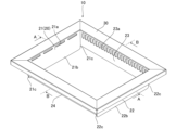
以下に、本発明のトップリングの一実施形態を無煙ロースターに用いたときの実施形態により図面を参照して説明する。図1に示したように、本発明のトップリング10は、テーブルやカウンターテーブル等の卓上に形成された開口部A内にガスヒータや炭等を用いた加熱部によりプレートBの上側の食材を加熱する無煙ロースター(ロースター)に用いられるものであり、開口部Aの周縁部を着脱可能に覆う4つ(複数)の角部を有する平面視で長方形の角形のトップリングである。本発明のトップリング10は、複数を上下に多段状に積み重ねて持ち運びやすくしたものである。
EMBODIMENT OF THE INVENTION Below, an embodiment of the top ring of the present invention when used in a smokeless roaster will be described with reference to the drawings. As shown in FIG. 1, the
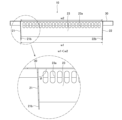
図2に示したように、トップリング10は、開口部Aの下側の側方を覆う平面視で略長方形の4つ(複数)の側壁21~24を有する角形筒部20と、角形筒部20の上端から外側に延出して開口部Aの外側周縁部の上面に当接するフランジ部30とを備えている。角形筒部20は、4つの側壁21~24と、これらの4つの側壁21~24の間に形成される4つの角部を有し、平面視で略長方形の筒形をしている。フランジ部30は平面視で略長方形の角形筒部20の上縁から外側に延出する平面視で略長方形の枠形状をしている。
As shown in FIG. 2, the
図1及び図2に示したように、角形筒部20は、幅の長さが短い方の短辺側の側壁21,22と、幅が長い方の長辺側の側壁23,24とを備えている。短辺側の側壁21,22の上部には水平方向に延びる4つの貫通孔21a(側壁22の貫通孔は図示省略した)が形成されており、これらの貫通孔21aは加熱部の熱がフランジ部30に伝わるのを抑制するために形成されている。また、長辺側の側壁23,24の上部には複数の吸気孔23a(側壁24の吸気孔は図示省略した)が形成されており、これらの吸気孔23aはプレートBの上側に発生した煙を開口部A内に設けた排気ダクトに送り出すためのものである。
As shown in FIGS. 1 and 2, the rectangular
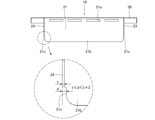
図2及び図3に示したように、角形筒部20は、互いに対向する短辺側の一対の側壁21,22の下部に他の側壁23,24の下端よりも下方に延びる一対の下方延出部21b,22bを備えている。側壁23,24が鉛直方向に延びているのに対し、一対の側壁21、22は下方延出部21b,22bを含めて下側に進むに従って角形筒部20の内側に直線的に傾斜している。この実施形態では、図3のθに示したように、側壁21,22は鉛直方向よりも1°内側に傾斜することで水平方向から内側に89°で傾斜している。一対の下方延出部21b,22bを下部に有する一対の側壁21,22を内側に傾斜させていることで、一対の下方延出部21b,22bの外側の間の長さw1は、一対の下方延出部21b,22bを有する一対の側壁21,22の上部の内側の間の長さw2よりも短くなっている。
As shown in FIGS. 2 and 3, the rectangular
図2に示したように、下方延出部21b,22bの幅方向の両端部には幅方向の内側に凹む凹部21c,22cが形成されている。図4に示したように、凹部21cは側壁21に隣接する側壁23,24の各々の厚みより少し大きく幅方向の内側に凹んでいる。凹部21cの幅方向の長さdを側壁21に隣接する側壁23,24の各々の厚みtより大きくすることで、互いに対向する一対の側壁21,22が同じ方向となるようにトップリング10を上下に積み重ねたときに、下方延出部21bを側壁23,24の間に挿通(嵌挿)することができるようになる。
As shown in FIG. 2, recesses 21c and 22c recessed inward in the width direction are formed at both widthwise ends of the downwardly extending
また、凹部21cは側壁21に隣接する側壁23,24の各々の厚みの2倍より小さく幅方向の内側に凹んでいる。凹部21cの幅方向の長さdを側壁21に隣接する側壁23,24の各々の厚みtの2倍(t×2)より小さくすることで、互いに対向する一対の側壁21,22が同じ方向となるようにトップリング10を上下に積み重ねたときに、上側のトップリング10が側壁21,22の幅方向にずれたとしても、下方延出部21bの幅方向の両端部の凹部21cにより生じる側壁23,24との間の隙間は側壁23,24の厚みより小さいので、上側のトップリング10が側壁23,24の厚みtよりも大きく移動せず、上側のトップリング10が一対の側壁21,22の幅方向に傾かないようになる。なお、側壁22に形成された凹部22cは、図4に示した側壁21に形成された凹部21cと同じであるので図示して説明するのを省略する。
Further, the recessed
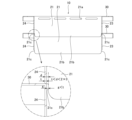
図5に示したように、トップリング10を一対の側壁21,22が並ぶ方向を同じ方向(長手方向が同じ方向)となるように上下に積み重ねたときに、図3に示したように、一対の下方延出部21b,22bの外側の間の長さw1は、一対の下方延出部21b,22bを有する一対の側壁21,22の上部の内側の間の長さw2よりも短くなっているので、図6に示したように、上側のトップリング10の一対の下方延出部21b,22bは下側のトップリング10の一対の側壁21,22の上部の間に嵌挿される。下側のトップリング10の一対の側壁21,22の上部の間に嵌挿される上側のトップリング10の一対の下方延出部21b,22bは、下側のトップリング10の一対の側壁21,22の上部の内側で移動が規制され、上側のトップリング10が一対の側壁21,22が配置される方向へ滑り落ちにくくなる。
As shown in FIG. 5, when the top rings 10 are stacked up and down so that the pair of
また、図7に示したように、上側のトップリング10の側壁21の下部の下方延出部21bは幅方向の両端部が直ぐ側方に隣接する側壁23,24の上部によって幅方向への移動が規制されているだけでなく、凹部21cと隣接する側壁23,24との間の隙間gが側壁23,24の各々の厚みtより小さいので、上側のトップリング10の側壁23,24の下端が下側のトップリング10の側壁23,24の上端またはフランジ部30から内側に滑り落ちにくくなる。なお、側壁22の下部の下方延出部22bについても同様である。
Further, as shown in FIG. 7, the downward extending
さらに、上側のトップリング10の下方延出部21b,22bが下側のトップリング10の一対の側壁21,22の上部の間に嵌挿されたときに、上側のトップリング10の一対の側壁21,22に隣接する他の側壁23,24の下端が下側のトップリング10の側壁23,24の上端またはフランジ部30に当接するので、上側のトップリング10の下方延出部21b,22bが下側のトップリング10の一対の側壁21,22の下部まで挿通されない。これにより、上側のトップリング10の下方延出部21b,22bが下側のトップリング10の一対の側壁21,22の間で強く嵌まり込むことに起因して、上側のトップリング10が下側のトップリング10から取り外しにくくならない。
Furthermore, when the downwardly extending
上記のように構成したトップリング10は、卓上に形成された開口部A内に設けた加熱部により食材を加熱する無煙ロースター(ロースター)に用いられ、開口部Aの周縁部を着脱可能に覆うものである。このトップリング10は、開口部Aの下側の側方を覆う4つ(複数)の側壁21~24と、これらの4つの側壁21~24の間に形成される複数の角部を有する角形筒部20と、角形筒部の上端から外側に延出して開口部Aの外側周縁部の上面に当接するフランジ部30とを備えた、所謂、角形のトップリングである。
The
このトップリング10においては、角形筒部20は互いに対向する一対の側壁21,22の下部に他の側壁23,24の下端よりも下方に延びる一対の下方延出部21b,22bを備え、一対の下方延出部21b,22bの外側の間の長さを一対の側壁21,22の上部の内側の間の長さよりも短くしている。一対の側壁21,22が並ぶ方向が同じ方向となるように、トップリング10を上下に積み重ねたときに、上側のトップリング10の一対の下方延出部21b,22bの外側の間の長さw1は、下側のトップリング10の一対の側壁21,22の上部の内側の間の長さw2よりも短いので、上側のトップリング10の一対の下方延出部21b,22bは下側のトップリング10の一対の側壁21,22の間の上部に嵌挿される。この状態では、上側のトップリング10の一対の下方延出部21b,22bは下側のトップリング10の一対の側壁21,22の上部の間で一対の側壁21,22が並ぶ方向への移動が規制されるので、上側のトップリング10が一対の側壁21,22が並ぶ方向で下側のトップリング10から滑り落ちにくくなり、トップリング10を上下に多段状に積み重ねて持ち運びやすくなる。また、トップリング10を上下に多段状に安定して積み重ねことができるので、広い保管場所を必要としないようにすることができる。
In this
また、一対の側壁21,22が並ぶ方向が同じ方向となるようにトップリング10を上下に積み重ねて、上側のトップリング10の一対の下方延出部21b,22bを下側のトップリング10の一対の側壁21,22の間の上部に嵌挿したときに、上側のトップリング10の一対の側壁21,22以外の他の側壁23,24の下端が下側のトップリング10の一対の側壁21,22以外の他の側壁23,24またはフランジ部30に当接することで、上側のトップリング10の一対の下方延出部21b,22bが下側のトップリング10の一対の側壁21,22の上部に嵌まり込まないようになり、上側のトップリング10は下側のトップリング10から取り外しにくくならない。
Furthermore, the top rings 10 are stacked vertically so that the pair of
このトップリング10においては、下方延出部21b,22bの幅方向の両端部には幅方向の内側に凹む凹部21c,22cが形成され、凹部21c,22cは下方延出部21b,22bを有する側壁21,22の両側に隣接する側壁23,24の各々の厚みtより大きく、隣接する側壁23,24の各々の厚みtの2倍より小さく形成されている。互いに対向する一対の側壁21,22が同じ方向となるようにトップリング10を上下に積み重ねたときに、凹部21c,22cは下方延出部21b,22bを有する側壁21,22の両側に隣接する側壁23,24の各々の厚みtより大きいので、上側のトップリング10の下方延出部21b,22bが凹部21c,22cによって一対の側壁21,22に隣接する側壁23,24の内側に挿通可能な状態となる。また、凹部21c,22cは下方延出部21b,22bを有する側壁21,22の両側に隣接する側壁23,24の各々の厚みtの2倍(2×t)より小さいので、下方延出部21b,22bの凹部21c,22cによって隣接する側壁23,24と間に形成される隙間gは当該隣接する側壁23,24の厚みtより小さくなり、上側のトップリング10が一対の側壁21,22の幅方向にずれても、上側のトップリング10が一対の側壁21,22に隣接する側壁23,24の厚みtの長さより大きく移動しないので、上側のトップリング10の一対の側壁21,22に隣接する側壁23,24が下側のトップリング10の一対の側壁21,22に隣接する側壁23,24またはフランジ部30に確実に当接し、上側のトップリング10が一対の側壁21,22の幅方向にずれることに起因して下側のトップリング10の内側に傾いて嵌まり込まないようになる。
In this
このトップリング10においては、下方延出部21b,22bを下部に有する一対の側壁21,22の各々は、下方延出部21b,22bを含めて下側に進むにしたがって角形筒部20の内側に直線的に傾斜させることで、一対の下方延出部21b,22bの外側の間の長さを一対の側壁21,22の上部の内側の間の長さよりも短くしている。このようにしたことで、トップリング10の加工に手間がかかりにくくなるだけでなく、下方延出部21b,22bを有する側壁21,22に段部が形成されないので、一対の側壁21,22に汚れが残りにくくすることができる。なお、この実施形態では、一対の側壁21,22は下方延出部21b,22bを含めて下側に進むにしたがって内側に直線的に傾斜させるようにすることで、一対の下方延出部21b,22bの外側の間の長さを一対の側壁21,22の上部の内側の間の長さよりも短くしているが、これに限られるものでなく、図8に示したように、側壁21,22を傾斜させることなく鉛直に延出させ、側壁21,22の下端部に水平方向(斜め下方であってもよい)の内側に延出する段部を形成し、段部の先端から下方に延びる下方延出部21b,22bを形成するようにしたものであってもよい。このようにしたときにも、上側のトップリング10が一対の側壁21,22が並ぶ方向で滑り落ちにくくすることができる。
In this
上記の実施形態のトップリング10の角形筒部20は、複数の側壁と、これらの複数の側壁の間に形成される複数の角部を有する角形筒部として平面視略長方形となっているが、これに限られるものでなく、平面視正方形としたものであってもよく、平面視四角形以上の多角形であればよく、さらに偶数の多角形、特に偶数の正多角形であるのが好ましい。また、角形筒部の各角部をアール形状として曲面形状としたものであってもよい。
The
10…トップリング、20…角形筒部、21,22…一対の側壁、21b,22b…一対の下方延出部、21c,22c…凹部、23,24…隣接する側壁、30…フランジ部、A…開口部。
DESCRIPTION OF
Claims (2)
前記開口部の下側の側方を覆う複数の側壁と、これらの複数の側壁の間に形成される複数の角部を有する角形筒部と、
前記角形筒部の上端から外側に延出して前記開口部の外側周縁部の上面に当接するフランジ部とを備え、
前記角形筒部は互いに対向する一対の側壁の下部に他の側壁の下端よりも下方に延びる一対の下方延出部を備え、
前記下方延出部を下部に有する前記一対の側壁の各々は、前記下方延出部を含めて下側に進むにしたがって前記角形筒部の内側に直線的に傾斜させることで、前記一対の下方延出部の外側の間の長さを前記一対の側壁の上部の内側の間の長さよりも短くしたことを特徴とするトップリング。 A top ring that is used in a roaster that heats foodstuffs with a heating part provided in an opening formed on a tabletop, and that removably covers the periphery of the opening,
a plurality of side walls covering the lower side of the opening, and a rectangular cylinder portion having a plurality of corners formed between the plurality of side walls;
a flange portion extending outward from the upper end of the square cylinder portion and abutting the upper surface of the outer peripheral edge of the opening;
The rectangular cylindrical portion includes a pair of downwardly extending portions at lower portions of a pair of side walls facing each other, which extend lower than the lower ends of the other side walls;
Each of the pair of side walls having the downwardly extending portion at the bottom is inclined linearly toward the inside of the rectangular cylindrical portion as it goes downward including the downwardly extending portion. A top ring characterized in that the length between the outsides of the extending portions is shorter than the length between the insides of the upper portions of the pair of side walls.
前記下方延出部の幅方向の両端部には前記幅方向の内側に凹む凹部が形成され、
前記凹部は、前記下方延出部を有する側壁の両側に隣接する側壁の各々の厚みより大きく、前記隣接する側壁の各々の厚みの2倍より小さく形成されたことを特徴とするトップリング。 The top ring according to claim 1,
A recessed portion recessed inward in the width direction is formed at both ends in the width direction of the downwardly extending portion,
The top ring is characterized in that the recessed portion is formed to have a thickness larger than each of the side walls adjacent to both sides of the side wall having the downwardly extending portion, and smaller than twice the thickness of each of the adjacent side walls.
Priority Applications (1)
| Application Number | Priority Date | Filing Date | Title |
|---|---|---|---|
| JP2020194977A JP7370077B2 (en) | 2020-11-25 | 2020-11-25 | top ring |
Applications Claiming Priority (1)
| Application Number | Priority Date | Filing Date | Title |
|---|---|---|---|
| JP2020194977A JP7370077B2 (en) | 2020-11-25 | 2020-11-25 | top ring |
Publications (2)
| Publication Number | Publication Date |
|---|---|
| JP2022083577A JP2022083577A (en) | 2022-06-06 |
| JP7370077B2 true JP7370077B2 (en) | 2023-10-27 |
Family
ID=81855599
Family Applications (1)
| Application Number | Title | Priority Date | Filing Date |
|---|---|---|---|
| JP2020194977A Active JP7370077B2 (en) | 2020-11-25 | 2020-11-25 | top ring |
Country Status (1)
| Country | Link |
|---|---|
| JP (1) | JP7370077B2 (en) |
Citations (1)
| Publication number | Priority date | Publication date | Assignee | Title |
|---|---|---|---|---|
| JP2006248621A (en) | 2005-03-08 | 2006-09-21 | Takao Fukuda | Connected garbage box for sorting |
Family Cites Families (5)
| Publication number | Priority date | Publication date | Assignee | Title |
|---|---|---|---|---|
| JPS61188925U (en) * | 1985-05-17 | 1986-11-25 | ||
| JPH0513329Y2 (en) * | 1987-03-07 | 1993-04-08 | ||
| JPS6480320A (en) * | 1987-09-19 | 1989-03-27 | Yanagen Kk | Roaster of charcoal burning type |
| JPH0523175Y2 (en) * | 1987-11-19 | 1993-06-14 | ||
| JPH0716733U (en) * | 1993-08-31 | 1995-03-20 | 株式会社河村晃清堂 | Grill with underframe |
-
2020
- 2020-11-25 JP JP2020194977A patent/JP7370077B2/en active Active
Patent Citations (1)
| Publication number | Priority date | Publication date | Assignee | Title |
|---|---|---|---|---|
| JP2006248621A (en) | 2005-03-08 | 2006-09-21 | Takao Fukuda | Connected garbage box for sorting |
Also Published As
| Publication number | Publication date |
|---|---|
| JP2022083577A (en) | 2022-06-06 |
Similar Documents
| Publication | Publication Date | Title |
|---|---|---|
| US10132502B2 (en) | Apparatus for cooking pizza in kettle- or kamado-style cooking grills | |
| US9215949B1 (en) | Modular griddle and grill frame with inserts | |
| US5676276A (en) | Buffet table food pan | |
| US20030167932A1 (en) | Stackable and configurable colander apparatus | |
| US20080169295A1 (en) | Method for removing a steam-table pan from a steam table | |
| US8960081B2 (en) | Steam cooking apparatus | |
| US20160106261A1 (en) | Modular Grill Frame With Inserts | |
| KR20190109058A (en) | A Direct fired roast grill pan | |
| JP7370077B2 (en) | top ring | |
| US10201245B2 (en) | Automatic broiler with air flow restriction plate | |
| WO2008045590A2 (en) | Roaster | |
| US5881633A (en) | Cooking apparatus having support for food manipulation means | |
| JP4915972B2 (en) | Food division storage container | |
| US20120048123A1 (en) | Steamer for foodstuffs | |
| JP3220129U (en) | Optional parts for cooker | |
| US20230292956A1 (en) | Griddle for barbecue grill or smoker | |
| JP3167908U (en) | Skewer holder | |
| US607759A (en) | Joseph mathy | |
| US20160174761A1 (en) | Cooking system and method of use | |
| US20250194854A1 (en) | Multi-purpose cookware | |
| KR200447619Y1 (en) | Cooking appliance | |
| US11226107B1 (en) | Oven debris collection system | |
| US913450A (en) | Cooking utensil. | |
| WO2015019038A1 (en) | Apparatus for cooking a chicken | |
| KR20110000010U (en) | Roaster having fat discharge structure |
Legal Events
| Date | Code | Title | Description |
|---|---|---|---|
| A621 | Written request for application examination |
Free format text: JAPANESE INTERMEDIATE CODE: A621 Effective date: 20220624 |
|
| A977 | Report on retrieval |
Free format text: JAPANESE INTERMEDIATE CODE: A971007 Effective date: 20230417 |
|
| A131 | Notification of reasons for refusal |
Free format text: JAPANESE INTERMEDIATE CODE: A131 Effective date: 20230425 |
|
| A521 | Request for written amendment filed |
Free format text: JAPANESE INTERMEDIATE CODE: A523 Effective date: 20230612 |
|
| TRDD | Decision of grant or rejection written | ||
| A01 | Written decision to grant a patent or to grant a registration (utility model) |
Free format text: JAPANESE INTERMEDIATE CODE: A01 Effective date: 20231003 |
|
| A61 | First payment of annual fees (during grant procedure) |
Free format text: JAPANESE INTERMEDIATE CODE: A61 Effective date: 20231010 |
|
| R150 | Certificate of patent or registration of utility model |
Ref document number: 7370077 Country of ref document: JP Free format text: JAPANESE INTERMEDIATE CODE: R150 |